F2A85-V User's Manual
Page 12
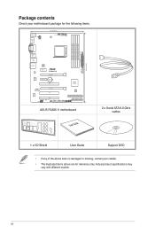
... Realtek ALC887 PCI2 SPDIF_OUT AAFP PCI3 SB_PWR CLRTC USB910 USB78 USB56 AMD® A85X 64Mb BIOS SATA6G_4 SATA6G_5 SATA6G_6 SATA6G_7 SATA6G_1 SATA6G_2 SATA6G_3 PANEL USB3_34 ASUS F2A85-V motherboard User Guide 2 x Serial ATA 6.0 Gb/s cables 1 x I/O Shield User Guide Support DVD • If any of the above items is damaged or missing, contact your...
... Realtek ALC887 PCI2 SPDIF_OUT AAFP PCI3 SB_PWR CLRTC USB910 USB78 USB56 AMD® A85X 64Mb BIOS SATA6G_4 SATA6G_5 SATA6G_6 SATA6G_7 SATA6G_1 SATA6G_2 SATA6G_3 PANEL USB3_34 ASUS F2A85-V motherboard User Guide 2 x Serial ATA 6.0 Gb/s cables 1 x I/O Shield User Guide Support DVD • If any of the above items is damaged or missing, contact your...
F2A85-V User's Manual
Page 13
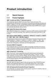
... bandwidth requirements of DDR3 2400(O.C.) / 2250(O.C.) / 2200(O.C.) / 2133(O.C.) / 2000(O.C.) / 1866 / 1600 / 1333 / 1066 MHz to boost the system's performance, and to get high quality images. ASUS F2A85-V 1-1 It features Dual-channel DDR3 memory support and accelerates data transfer rate up to ten times faster than USB 2.0. AMD® A85X FCH (Hudson D4...
... bandwidth requirements of DDR3 2400(O.C.) / 2250(O.C.) / 2200(O.C.) / 2133(O.C.) / 2000(O.C.) / 1866 / 1600 / 1333 / 1066 MHz to boost the system's performance, and to get high quality images. ASUS F2A85-V 1-1 It features Dual-channel DDR3 memory support and accelerates data transfer rate up to ten times faster than USB 2.0. AMD® A85X FCH (Hudson D4...
F2A85-V User's Manual
Page 15
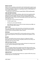
... settings, adjust the frequencies and related voltages, remotely control the system via a mobile device, and other easy-to-use . ASUS EZ Flash 2 ASUS EZ Flash 2 is an intuitive one-step network control center that makes it easier for you to manage your bandwidth and allows...to simply press a button to patch memory issues, ensure memory boot compatibility, determine fail-safe settings, and dramatically improve the system's bootup. ASUS F2A85-V 1-3 It allows you the adrenaline rush of real-time overclocking without using a bootable floppy disk or an OS-based utility. Network iControl...
... settings, adjust the frequencies and related voltages, remotely control the system via a mobile device, and other easy-to-use . ASUS EZ Flash 2 ASUS EZ Flash 2 is an intuitive one-step network control center that makes it easier for you to manage your bandwidth and allows...to simply press a button to patch memory issues, ensure memory boot compatibility, determine fail-safe settings, and dramatically improve the system's bootup. ASUS F2A85-V 1-3 It allows you the adrenaline rush of real-time overclocking without using a bootable floppy disk or an OS-based utility. Network iControl...
F2A85-V User's Manual
Page 17
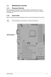
Doing so can damage the motherboard. DO NOT overtighten the screws! F2A85-V ASUS F2A85-V 1-5 1.3 Motherboard overview 1.3.1 Placement direction When installing the motherboard, ensure that you place it into the holes indicated by circles to secure the motherboard to the rear part of the chassis. The edge with external ports goes to the chassis. Place this side towards the rear of the chassis as indicated in the image below. 1.3.2 Screw holes Place six screws into the chassis in the correct orientation.
Doing so can damage the motherboard. DO NOT overtighten the screws! F2A85-V ASUS F2A85-V 1-5 1.3 Motherboard overview 1.3.1 Placement direction When installing the motherboard, ensure that you place it into the holes indicated by circles to secure the motherboard to the rear part of the chassis. The edge with external ports goes to the chassis. Place this side towards the rear of the chassis as indicated in the image below. 1.3.2 Screw holes Place six screws into the chassis in the correct orientation.
F2A85-V User's Manual
Page 19
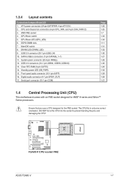
... force the CPU into the socket to prevent bending the pins and damaging the CPU! MemOK! The CPU fits in only one correct orientation. F2A85-V F2A85-V CPU socket FM2 ASUS F2A85-V 1-7 CPU and chassis fan connectors (4-pin CPU_FAN, and 4-pin CHA_FAN1/2) 3. Digital audio connector (4-1 pin SPDIF_OUT) 17. switch 8. Front panel audio connector (10-1 pin...
... force the CPU into the socket to prevent bending the pins and damaging the CPU! MemOK! The CPU fits in only one correct orientation. F2A85-V F2A85-V CPU socket FM2 ASUS F2A85-V 1-7 CPU and chassis fan connectors (4-pin CPU_FAN, and 4-pin CHA_FAN1/2) 3. Digital audio connector (4-1 pin SPDIF_OUT) 17. switch 8. Front panel audio connector (10-1 pin...
F2A85-V User's Manual
Page 21
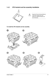
1.4.2 CPU heatsink and fan assembly installation Apply the Thermal Interface Material to the CPU heatsink and CPU before you install the heatsink and fan if necessary. To install the CPU heatsink and fan assembly 1 2 3 4 5 ASUS F2A85-V 1-9
1.4.2 CPU heatsink and fan assembly installation Apply the Thermal Interface Material to the CPU heatsink and CPU before you install the heatsink and fan if necessary. To install the CPU heatsink and fan assembly 1 2 3 4 5 ASUS F2A85-V 1-9
F2A85-V User's Manual
Page 23
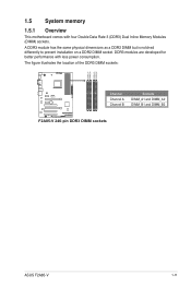
1.5 System memory 1.5.1 Overview This motherboard comes with less power consumption. A DDR3 module has the same physical dimensions as a DDR2 DIMM but is notched differently to prevent installation on a DDR2 DIMM socket. The figure illustrates the location of the DDR3 DIMM sockets: DIMM_A1 DIMM_A2 DIMM_B1 DIMM_B2 Channel Sockets F2A85-V Channel A DIMM_A1 and DIMM_A2 Channel B DIMM_B1 and DIMM_B2 F2A85-V 240-pin DDR3 DIMM sockets ASUS F2A85-V 1-11 DDR3 modules are developed for better performance with four Double Data Rate 3 (DDR3) Dual Inline Memory Modules (DIMM) sockets.
1.5 System memory 1.5.1 Overview This motherboard comes with less power consumption. A DDR3 module has the same physical dimensions as a DDR2 DIMM but is notched differently to prevent installation on a DDR2 DIMM socket. The figure illustrates the location of the DDR3 DIMM sockets: DIMM_A1 DIMM_A2 DIMM_B1 DIMM_B2 Channel Sockets F2A85-V Channel A DIMM_A1 and DIMM_A2 Channel B DIMM_B1 and DIMM_B2 F2A85-V 240-pin DDR3 DIMM sockets ASUS F2A85-V 1-11 DDR3 modules are developed for better performance with four Double Data Rate 3 (DDR3) Dual Inline Memory Modules (DIMM) sockets.
F2A85-V User's Manual
Page 31
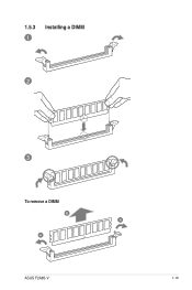
1.5.3 1 Installing a DIMM 2 3 To remove a DIMM B A A ASUS F2A85-V 1-19
1.5.3 1 Installing a DIMM 2 3 To remove a DIMM B A A ASUS F2A85-V 1-19
F2A85-V User's Manual
Page 33
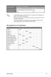
... details. • Connect a chassis fan to get better performance. • We recommend that you provide sufficient power when running CrossFireX™ mode. shared - - - shared - shared ASUS F2A85-V 1-21 shared - - shared - - - - - -
... details. • Connect a chassis fan to get better performance. • We recommend that you provide sufficient power when running CrossFireX™ mode. shared - - - shared - shared ASUS F2A85-V 1-21 shared - - shared - - - - - -
F2A85-V User's Manual
Page 35
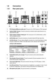
... below for the LAN port LED indications. Rear Speaker Out port (black). Line Out port (lime). Microphone port (pink). Refer to the center/subwoofer speakers. 7. ASUS F2A85-V 1-23 This port allows Gigabit connection to the rear speakers in the 4, 6, and 8-channel audio configurations. 8. PS/2 Keyboard/Mouse combo port. LAN (RJ-45) port...
... below for the LAN port LED indications. Rear Speaker Out port (black). Line Out port (lime). Microphone port (pink). Refer to the center/subwoofer speakers. 7. ASUS F2A85-V 1-23 This port allows Gigabit connection to the rear speakers in the 4, 6, and 8-channel audio configurations. 8. PS/2 Keyboard/Mouse combo port. LAN (RJ-45) port...
F2A85-V User's Manual
Page 37
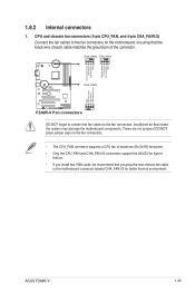
These are not jumpers! ASUS F2A85-V 1-25 CPU and chassis fan connectors (4-pin CPU_FAN, and 4-pin CHA_FAN1/2) Connect the fan cables to the motherboard connector labeled CHA_FAN1/2 for better thermal environment. ... the fan connectors. • The CPU_FAN connector supports a CPU fan of maximum 2A (24 W) fan power. • Only the CPU_FAN and CHA_FAN1/2 connectors support the ASUS Fan Xpert+ feature. • If you install two VGA cards, we recommend that you plug the rear chassis fan cable to the fan connectors on...
These are not jumpers! ASUS F2A85-V 1-25 CPU and chassis fan connectors (4-pin CPU_FAN, and 4-pin CHA_FAN1/2) Connect the fan cables to the motherboard connector labeled CHA_FAN1/2 for better thermal environment. ... the fan connectors. • The CPU_FAN connector supports a CPU fan of maximum 2A (24 W) fan power. • Only the CPU_FAN and CHA_FAN1/2 connectors support the ASUS Fan Xpert+ feature. • If you install two VGA cards, we recommend that you plug the rear chassis fan cable to the fan connectors on...
F2A85-V User's Manual
Page 39
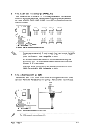
...) connector The COM module is for details. 4. Serial port connector (10-1 pin COM) This connector is purchased separately. ASUS F2A85-V 1-27 If you installed Serial ATA hard disk drives, you intend to create a Serial ATA RAID set the type of... RSATA_TXP6 RSATA_TXN6 GND RSATA_RXN6 RSATA_RXP6 GND GND RSATA_TXP5 RSATA_TXN5 GND RSATA_RXN5 RSATA_RXP5 GND GND RSATA_TXP4 RSATA_TXN4 GND RSATA_RXN4 RSATA_RXP4 GND F2A85-V SATA6G_1 SATA6G_2 SATA6G_3 GND RSATA_RXP3 RSATA_RXN3 GND RSATA_TXN3 RSATA_TXP3 GND GND RSATA_RXP2 RSATA_RXN2 GND RSATA_TXN2 RSATA_TXP2 GND GND RSATA_RXP1 RSATA_RXN1 GND...
...) connector The COM module is for details. 4. Serial port connector (10-1 pin COM) This connector is purchased separately. ASUS F2A85-V 1-27 If you installed Serial ATA hard disk drives, you intend to create a Serial ATA RAID set the type of... RSATA_TXP6 RSATA_TXN6 GND RSATA_RXN6 RSATA_RXP6 GND GND RSATA_TXP5 RSATA_TXN5 GND RSATA_RXN5 RSATA_RXP5 GND GND RSATA_TXP4 RSATA_TXN4 GND RSATA_RXN4 RSATA_RXP4 GND F2A85-V SATA6G_1 SATA6G_2 SATA6G_3 GND RSATA_RXP3 RSATA_RXN3 GND RSATA_TXN3 RSATA_TXP3 GND GND RSATA_RXP2 RSATA_RXN2 GND RSATA_TXN2 RSATA_TXP2 GND GND RSATA_RXP1 RSATA_RXN1 GND...
F2A85-V User's Manual
Page 41
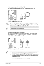
ASUS F2A85-V 1-29 Front panel audio connector (10-1 pin AAFP) This connector is ...audio connector (4-1 pin SPDIF_OUT) This connector is for an additional Sony/Philips Digital Interface (S/PDIF) port. +5V SPDIFOUT GND F2A85-V SPDIF_OUT F2A85-V Digital audio connector Ensure that the audio device of the motherboard high-definition audio capability. • If you want to...panel audio I /O module cable to [HD]. AGND NC SENSE1_RETUR SENSE2_RETUR AGND NC NC NC F2A85-V AAFP PIN 1 MIC2 MICPWR Line out_R NC Line out_L PORT1 L PORT1 R PORT2 R SENSE_SEND PORT2 L HD-audio-compliant...
ASUS F2A85-V 1-29 Front panel audio connector (10-1 pin AAFP) This connector is ...audio connector (4-1 pin SPDIF_OUT) This connector is for an additional Sony/Philips Digital Interface (S/PDIF) port. +5V SPDIFOUT GND F2A85-V SPDIF_OUT F2A85-V Digital audio connector Ensure that the audio device of the motherboard high-definition audio capability. • If you want to...panel audio I /O module cable to [HD]. AGND NC SENSE1_RETUR SENSE2_RETUR AGND NC NC NC F2A85-V AAFP PIN 1 MIC2 MICPWR Line out_R NC Line out_L PORT1 L PORT1 R PORT2 R SENSE_SEND PORT2 L HD-audio-compliant...
F2A85-V User's Manual
Page 43
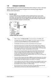
The blinking speed of failsafe settings. switch to section 1.10 Onboard LEDs for the exact location of failsafe settings. ASUS F2A85-V 1-31 switch until the DRAM_LED starts blinking to begin automatic memory compatibility tuning for overclockers and gamers who continually change settings to ... We recommend that are incompatible with ones recommended in the Memory QVL (Qualified Vendors Lists) in this user manual or on the ASUS website at www.asus.com after using the MemOK! Press and hold the MemOK! Replace the DIMMs with the motherboard may cause system boot failure, and...
The blinking speed of failsafe settings. switch to section 1.10 Onboard LEDs for the exact location of failsafe settings. ASUS F2A85-V 1-31 switch until the DRAM_LED starts blinking to begin automatic memory compatibility tuning for overclockers and gamers who continually change settings to ... We recommend that are incompatible with ones recommended in the Memory QVL (Qualified Vendors Lists) in this user manual or on the ASUS website at www.asus.com after using the MemOK! Press and hold the MemOK! Replace the DIMMs with the motherboard may cause system boot failure, and...
F2A85-V User's Manual
Page 45
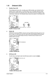
...or plugging in sequence during motherboard booting process. GPU Boost LED The GPU Boost LED lights when the GPU Boost switch is solved. F2A85-V SB_PWR F2A85-V Onboard LED ON OFF Standby Power Powered Off 2. The illustration below shows the location of the onboard LED. This is ON, ...in sleep mode, or in soft-off mode. DRAM LED DRAM LED checks the DRAM in any motherboard component. GPU_LED F2A85-V F2A85-V GPU Boost LED ASUS F2A85-V 1-33 Standby Power LED The motherboard comes with a standby power LED that lights up to locate the root problem within a second....
...or plugging in sequence during motherboard booting process. GPU Boost LED The GPU Boost LED lights when the GPU Boost switch is solved. F2A85-V SB_PWR F2A85-V Onboard LED ON OFF Standby Power Powered Off 2. The illustration below shows the location of the onboard LED. This is ON, ...in sleep mode, or in soft-off mode. DRAM LED DRAM LED checks the DRAM in any motherboard component. GPU_LED F2A85-V F2A85-V GPU Boost LED ASUS F2A85-V 1-33 Standby Power LED The motherboard comes with a standby power LED that lights up to locate the root problem within a second....
F2A85-V User's Manual
Page 48
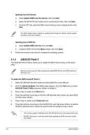
... the update process is capable of the BIOS setup program. Always update the utility to prevent system boot failure! 2-2 ASUS F2A85-V Locate the BIOS file from the ASUS website at www.asus.com. Before you wish to the Folder Info field. 6. Press the Up/Down arrow keys to find the BIOS... FTP site, select the BIOS version that contains the latest BIOS, and then press . 5. b. Select Update BIOS from the Internet a. b. Select the ASUS FTP site nearest you to find the USB flash disk that you start using this utility, download the latest BIOS file from the Open window...
... the update process is capable of the BIOS setup program. Always update the utility to prevent system boot failure! 2-2 ASUS F2A85-V Locate the BIOS file from the ASUS website at www.asus.com. Before you wish to the Folder Info field. 6. Press the Up/Down arrow keys to find the BIOS... FTP site, select the BIOS version that contains the latest BIOS, and then press . 5. b. Select Update BIOS from the Internet a. b. Select the ASUS FTP site nearest you to find the USB flash disk that you start using this utility, download the latest BIOS file from the Open window...
F2A85-V User's Manual
Page 50
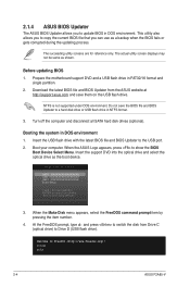
... selection ENTER to select boot device ESC to FreeDOS (http://www.freedos.org)! C:\>d: D:\> 2-4 ASUS F2A85-V At the FreeDOS prompt, type d: and press to switch the disk from the ASUS website at http://support.asus.com and save the BIOS file and BIOS Updater to update BIOS in DOS environment 1. The ...actual utility screen displays may not be same as shown. 2.1.4 ASUS BIOS Updater The ASUS BIOS Updater allows you can use as the boot device. When the ASUS Logo appears, press to the USB port. 2. Insert the USB flash drive with the latest BIOS...
... selection ENTER to select boot device ESC to FreeDOS (http://www.freedos.org)! C:\>d: D:\> 2-4 ASUS F2A85-V At the FreeDOS prompt, type d: and press to switch the disk from the ASUS website at http://support.asus.com and save the BIOS file and BIOS Updater to update BIOS in DOS environment 1. The ...actual utility screen displays may not be same as shown. 2.1.4 ASUS BIOS Updater The ASUS BIOS Updater allows you can use as the boot device. When the ASUS Logo appears, press to the USB port. 2. Insert the USB flash drive with the latest BIOS...

F2A85-V User's Manual
Page 52
... system properly from the operating system. • The BIOS setup screens shown in this option only if you in the EZ Mode/Advanced Mode screen. 2-6 ASUS F2A85-V Select the Load Optimized Defaults item under two modes: EZ Mode and Advanced Mode. You can change modes from the Exit menu or from a running...
... system properly from the operating system. • The BIOS setup screens shown in this option only if you in the EZ Mode/Advanced Mode screen. 2-6 ASUS F2A85-V Select the Load Optimized Defaults item under two modes: EZ Mode and Advanced Mode. You can change modes from the Exit menu or from a running...
F2A85-V User's Manual
Page 54
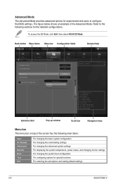
... an example of the screen has the following sections for special functions For selecting the exit options and loading default settings 2-8 ASUS F2A85-V To access the EZ Mode, click Exit, then select ASUS EZ Mode. Advanced Mode General help Exit Main Back Ai Tweaker Advanced Advanced\ Onboard Devices Configuration > Monitor HD Audio Device...
... an example of the screen has the following sections for special functions For selecting the exit options and loading default settings 2-8 ASUS F2A85-V To access the EZ Mode, click Exit, then select ASUS EZ Mode. Advanced Mode General help Exit Main Back Ai Tweaker Advanced Advanced\ Onboard Devices Configuration > Monitor HD Audio Device...
F2A85-V User's Manual
Page 56
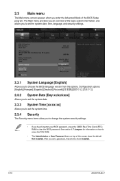
... The Security menu items allow you to change the system security settings. • If you enter the Advanced Mode of the screen show Installed. 2-10 ASUS F2A85-V 2.3 Main menu The Main menu screen appears when you have forgotten your BIOS password, erase the CMOS Real Time Clock (RTC) RAM to clear the...
... The Security menu items allow you to change the system security settings. • If you enter the Advanced Mode of the screen show Installed. 2-10 ASUS F2A85-V 2.3 Main menu The Main menu screen appears when you have forgotten your BIOS password, erase the CMOS Real Time Clock (RTC) RAM to clear the...


