F2A85-V User's Manual
Page 12
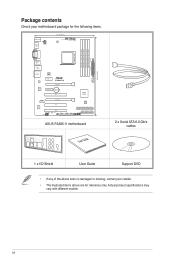
..._USB12 DRAM_LED MemOK! xii Actual product specifications may vary with different models. EATXPWR AUDIO Atheros 8161 Super I/O CHA_FAN1 PCIEX1_1 F2A85-V PCIEX16_1 PCIEX1_2 Lithium Cell CMOS Power PCI1 COM PCIEX16_2 Realtek ALC887 PCI2 SPDIF_OUT AAFP PCI3 SB_PWR CLRTC USB910 USB78 USB56... AMD® A85X 64Mb BIOS SATA6G_4 SATA6G_5 SATA6G_6 SATA6G_7 SATA6G_1 SATA6G_2 SATA6G_3 PANEL USB3_34 ASUS F2A85-V motherboard User Guide 2 x Serial ATA 6.0 Gb/s cables 1 x I/O Shield User Guide Support DVD • If any of...
..._USB12 DRAM_LED MemOK! xii Actual product specifications may vary with different models. EATXPWR AUDIO Atheros 8161 Super I/O CHA_FAN1 PCIEX1_1 F2A85-V PCIEX16_1 PCIEX1_2 Lithium Cell CMOS Power PCI1 COM PCIEX16_2 Realtek ALC887 PCI2 SPDIF_OUT AAFP PCI3 SB_PWR CLRTC USB910 USB78 USB56... AMD® A85X 64Mb BIOS SATA6G_4 SATA6G_5 SATA6G_6 SATA6G_7 SATA6G_1 SATA6G_2 SATA6G_3 PANEL USB3_34 ASUS F2A85-V motherboard User Guide 2 x Serial ATA 6.0 Gb/s cables 1 x I/O Shield User Guide Support DVD • If any of...
F2A85-V User's Manual
Page 13
... rate up to ten times faster than USB 2.0. It also supports 8 x SATA 6.0Gb/s ports and 4 x USB 3.0 ports. Dual-Channel DDR3 2400(O.C.) / 2250(O.C.) / 2200(O.C.) / 2133(O.C.) / 2000(O. ASUS F2A85-V 1-1 AMD® A85X FCH (Hudson D4) chipset AMD® A85X FCH (Hudson D4) is designed to support up to 6.0 Gb/s data transfer rates. C.) / 1866 / 1600...
... rate up to ten times faster than USB 2.0. It also supports 8 x SATA 6.0Gb/s ports and 4 x USB 3.0 ports. Dual-Channel DDR3 2400(O.C.) / 2250(O.C.) / 2200(O.C.) / 2133(O.C.) / 2000(O. ASUS F2A85-V 1-1 AMD® A85X FCH (Hudson D4) chipset AMD® A85X FCH (Hudson D4) is designed to support up to 6.0 Gb/s data transfer rates. C.) / 1866 / 1600...
F2A85-V User's Manual
Page 15
... graphics performance, facilitates flexible frequency adjustments, and easily delivers stable system-level upgrades for most accessed information • ASUS DRAM SPD (Serial Presence Detect) information detecting faulty DIMMs, and helping with difficult POST situations. Network iControl Network ...mouse-controlled intuitive graphical BIOS interface that allows you to update the BIOS without exiting or rebooting the OS. ASUS F2A85-V 1-3 MemOK! ASUS Anti-Surge Protection This special design protects expensive devices and the motherboard from damage caused by power surges from switching...
... graphics performance, facilitates flexible frequency adjustments, and easily delivers stable system-level upgrades for most accessed information • ASUS DRAM SPD (Serial Presence Detect) information detecting faulty DIMMs, and helping with difficult POST situations. Network iControl Network ...mouse-controlled intuitive graphical BIOS interface that allows you to update the BIOS without exiting or rebooting the OS. ASUS F2A85-V 1-3 MemOK! ASUS Anti-Surge Protection This special design protects expensive devices and the motherboard from damage caused by power surges from switching...
F2A85-V User's Manual
Page 17
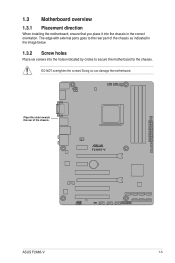
Doing so can damage the motherboard. The edge with external ports goes to the chassis. Place this side towards the rear of the chassis as indicated in the image below. 1.3.2 Screw holes Place six screws into the chassis in the correct orientation. F2A85-V ASUS F2A85-V 1-5 DO NOT overtighten the screws! 1.3 Motherboard overview 1.3.1 Placement direction When installing the motherboard, ensure that you place it into the holes indicated by circles to secure the motherboard to the rear part of the chassis.
Doing so can damage the motherboard. The edge with external ports goes to the chassis. Place this side towards the rear of the chassis as indicated in the image below. 1.3.2 Screw holes Place six screws into the chassis in the correct orientation. F2A85-V ASUS F2A85-V 1-5 DO NOT overtighten the screws! 1.3 Motherboard overview 1.3.1 Placement direction When installing the motherboard, ensure that you place it into the holes indicated by circles to secure the motherboard to the rear part of the chassis.
F2A85-V User's Manual
Page 19
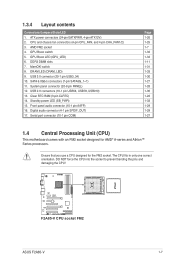
... connectors (4-pin CPU_FAN, and 4-pin CHA_FAN1/2) 3. DRAM LED (DRAM_LED) 9. System panel connector (20-8 pin PANEL) 12. The CPU fits in only one correct orientation. F2A85-V F2A85-V CPU socket FM2 ASUS F2A85-V 1-7 GPU Boost switch 5. Clear RTC RAM (3-pin CLRTC) 14. Standby power LED (SB_PWR) 15. Serial port connector (10-1 pin COM) Page 1-26 1-25...
... connectors (4-pin CPU_FAN, and 4-pin CHA_FAN1/2) 3. DRAM LED (DRAM_LED) 9. System panel connector (20-8 pin PANEL) 12. The CPU fits in only one correct orientation. F2A85-V F2A85-V CPU socket FM2 ASUS F2A85-V 1-7 GPU Boost switch 5. Clear RTC RAM (3-pin CLRTC) 14. Standby power LED (SB_PWR) 15. Serial port connector (10-1 pin COM) Page 1-26 1-25...
F2A85-V User's Manual
Page 21
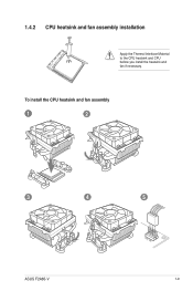
1.4.2 CPU heatsink and fan assembly installation Apply the Thermal Interface Material to the CPU heatsink and CPU before you install the heatsink and fan if necessary. To install the CPU heatsink and fan assembly 1 2 3 4 5 ASUS F2A85-V 1-9
1.4.2 CPU heatsink and fan assembly installation Apply the Thermal Interface Material to the CPU heatsink and CPU before you install the heatsink and fan if necessary. To install the CPU heatsink and fan assembly 1 2 3 4 5 ASUS F2A85-V 1-9
F2A85-V User's Manual
Page 23
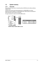
A DDR3 module has the same physical dimensions as a DDR2 DIMM but is notched differently to prevent installation on a DDR2 DIMM socket. The figure illustrates the location of the DDR3 DIMM sockets: DIMM_A1 DIMM_A2 DIMM_B1 DIMM_B2 Channel Sockets F2A85-V Channel A DIMM_A1 and DIMM_A2 Channel B DIMM_B1 and DIMM_B2 F2A85-V 240-pin DDR3 DIMM sockets ASUS F2A85-V 1-11 DDR3 modules are developed for better performance with four Double Data Rate 3 (DDR3) Dual Inline Memory Modules (DIMM) sockets. 1.5 System memory 1.5.1 Overview This motherboard comes with less power consumption.
A DDR3 module has the same physical dimensions as a DDR2 DIMM but is notched differently to prevent installation on a DDR2 DIMM socket. The figure illustrates the location of the DDR3 DIMM sockets: DIMM_A1 DIMM_A2 DIMM_B1 DIMM_B2 Channel Sockets F2A85-V Channel A DIMM_A1 and DIMM_A2 Channel B DIMM_B1 and DIMM_B2 F2A85-V 240-pin DDR3 DIMM sockets ASUS F2A85-V 1-11 DDR3 modules are developed for better performance with four Double Data Rate 3 (DDR3) Dual Inline Memory Modules (DIMM) sockets. 1.5 System memory 1.5.1 Overview This motherboard comes with less power consumption.
F2A85-V User's Manual
Page 31
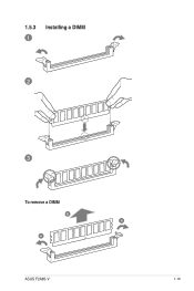
1.5.3 1 Installing a DIMM 2 3 To remove a DIMM B A A ASUS F2A85-V 1-19
1.5.3 1 Installing a DIMM 2 3 To remove a DIMM B A A ASUS F2A85-V 1-19
F2A85-V User's Manual
Page 33
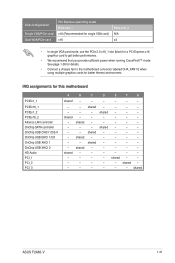
... controller OnChip USB OHCI 1/2/3/4 OnChip USB EHCI 1/2/3 OnChip USB XHCI 1 OnChip USB XHCI 2 HD Audio PCI_1 PCI_2 PCI_3 A B C D E F G shared - - - - - - - - shared shared - - - - - - shared - - shared - shared - - - shared ASUS F2A85-V 1-21 shared -
... controller OnChip USB OHCI 1/2/3/4 OnChip USB EHCI 1/2/3 OnChip USB XHCI 1 OnChip USB XHCI 2 HD Audio PCI_1 PCI_2 PCI_3 A B C D E F G shared - - - - - - - - shared shared - - - - - - shared - - shared - shared - - - shared ASUS F2A85-V 1-21 shared -
F2A85-V User's Manual
Page 35
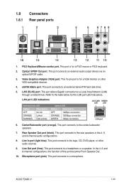
... LAN port 6. Center/Subwoofer port (orange). Rear Speaker Out port (black). eSATA 6Gb/s port. This port connects to a Local Area Network (LAN) through a network hub. ASUS F2A85-V 1-23 PS/2 Keyboard/Mouse combo port. Video Graphics Adapter (VGA) port. This port allows Gigabit connection to a headphone or a speaker. Line In port (light blue...
... LAN port 6. Center/Subwoofer port (orange). Rear Speaker Out port (black). eSATA 6Gb/s port. This port connects to a Local Area Network (LAN) through a network hub. ASUS F2A85-V 1-23 PS/2 Keyboard/Mouse combo port. Video Graphics Adapter (VGA) port. This port allows Gigabit connection to a headphone or a speaker. Line In port (light blue...
F2A85-V User's Manual
Page 37
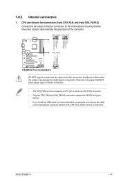
These are not jumpers! ASUS F2A85-V 1-25 DO NOT place jumper caps on the motherboard, ensuring that the black wire of each cable matches the ground pin of maximum 2A (24 W) fan power. • Only the CPU_FAN and CHA_FAN1/2 connectors support the ASUS Fan Xpert+ feature. • If you install two VGA cards, we... PWM CPU FAN IN CPU FAN PWR GND CHA FAN DC Mode CHA FAN IN CHA FAN PWR GND F2A85-V CHA_FAN1 GND CHA FAN PWR CHA FAN IN CHA FAN DC Mode F2A85-V Fan connectors DO NOT forget to connect the fan cables to the fan connectors on the fan connectors. •...
These are not jumpers! ASUS F2A85-V 1-25 DO NOT place jumper caps on the motherboard, ensuring that the black wire of each cable matches the ground pin of maximum 2A (24 W) fan power. • Only the CPU_FAN and CHA_FAN1/2 connectors support the ASUS Fan Xpert+ feature. • If you install two VGA cards, we... PWM CPU FAN IN CPU FAN PWR GND CHA FAN DC Mode CHA FAN IN CHA FAN PWR GND F2A85-V CHA_FAN1 GND CHA FAN PWR CHA FAN IN CHA FAN DC Mode F2A85-V Fan connectors DO NOT forget to connect the fan cables to the fan connectors on the fan connectors. •...
F2A85-V User's Manual
Page 39
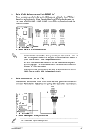
...RSATA_TXN3 RSATA_TXP3 GND GND RSATA_RXP2 RSATA_RXN2 GND RSATA_TXN2 RSATA_TXP2 GND GND RSATA_RXP1 RSATA_RXN1 GND RSATA_TXN1 RSATA_TXP1 GND F2A85-V SATA 6.0Gb/s connectors • These connectors are set to [RAID]. ASUS F2A85-V 1-27 If you intend to create a Serial ATA RAID set using these connectors, set...purchased separately. See section 2.5.2 SATA Configuration for a serial (COM) port. COM PIN 1 RXD DTR DSR CTS DCD TXD GND RTS RI F2A85-V F2A85-V Serial port (COM) connector The COM module is for details. 4. 3. If you installed Serial ATA hard disk drives, you are for ...
...RSATA_TXN3 RSATA_TXP3 GND GND RSATA_RXP2 RSATA_RXN2 GND RSATA_TXN2 RSATA_TXP2 GND GND RSATA_RXP1 RSATA_RXN1 GND RSATA_TXN1 RSATA_TXP1 GND F2A85-V SATA 6.0Gb/s connectors • These connectors are set to [RAID]. ASUS F2A85-V 1-27 If you intend to create a Serial ATA RAID set using these connectors, set...purchased separately. See section 2.5.2 SATA Configuration for a serial (COM) port. COM PIN 1 RXD DTR DSR CTS DCD TXD GND RTS RI F2A85-V F2A85-V Serial port (COM) connector The COM module is for details. 4. 3. If you installed Serial ATA hard disk drives, you are for ...
F2A85-V User's Manual
Page 41
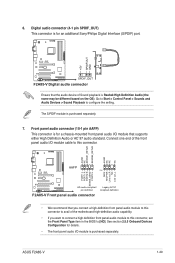
...• If you want to connect a high definition front panel audio module to this connector. 6. AGND NC SENSE1_RETUR SENSE2_RETUR AGND NC NC NC F2A85-V AAFP PIN 1 MIC2 MICPWR Line out_R NC Line out_L PORT1 L PORT1 R PORT2 R SENSE_SEND PORT2 L HD-audio-compliant pin definition...on the OS). Connect one end of Sound playback is for details. • The front panel audio I /O module cable to configure the setting. ASUS F2A85-V 1-29 Digital audio connector (4-1 pin SPDIF_OUT) This connector is for an additional Sony/Philips Digital Interface (S/PDIF) port. +5V SPDIFOUT GND...
...• If you want to connect a high definition front panel audio module to this connector. 6. AGND NC SENSE1_RETUR SENSE2_RETUR AGND NC NC NC F2A85-V AAFP PIN 1 MIC2 MICPWR Line out_R NC Line out_L PORT1 L PORT1 R PORT2 R SENSE_SEND PORT2 L HD-audio-compliant pin definition...on the OS). Connect one end of Sound playback is for details. • The front panel audio I /O module cable to configure the setting. ASUS F2A85-V 1-29 Digital audio connector (4-1 pin SPDIF_OUT) This connector is for an additional Sony/Philips Digital Interface (S/PDIF) port. +5V SPDIFOUT GND...
F2A85-V User's Manual
Page 43
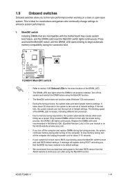
...when working on the computer. F2A85-V F2A85-V MemOK! Turn off the system and reinstall the DIMM before using the MemOK! Replace the DIMMs with ones recommended in the Memory QVL (Qualified Vendors Lists) in this user manual or on the ASUS website at www.asus.com after using the MemOK! ... test processes. • Due to BIOS overclocking, press the MemOK! If the installed DIMMs still fail to boot and load BIOS default settings. ASUS F2A85-V 1-31 1.9 Onboard switches Onboard switches allow you turn off the computer and unplug the power cord for the exact location of the DRAM_LED. &#...
...when working on the computer. F2A85-V F2A85-V MemOK! Turn off the system and reinstall the DIMM before using the MemOK! Replace the DIMMs with ones recommended in the Memory QVL (Qualified Vendors Lists) in this user manual or on the ASUS website at www.asus.com after using the MemOK! ... test processes. • Due to BIOS overclocking, press the MemOK! If the installed DIMMs still fail to boot and load BIOS default settings. ASUS F2A85-V 1-31 1.9 Onboard switches Onboard switches allow you turn off the computer and unplug the power cord for the exact location of the DRAM_LED. &#...
F2A85-V User's Manual
Page 45
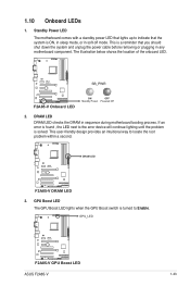
This is ON, in sleep mode, or in soft-off mode. F2A85-V SB_PWR F2A85-V Onboard LED ON OFF Standby Power Powered Off 2. F2A85-V DRAM LED F2A85-V DRAM LED 3. DRAM LED DRAM LED checks the DRAM in any motherboard component. If an error is solved. GPU Boost ...you should shut down the system and unplug the power cable before removing or plugging in sequence during motherboard booting process. GPU_LED F2A85-V F2A85-V GPU Boost LED ASUS F2A85-V 1-33 The illustration below shows the location of the onboard LED. This user-friendly design provides an intuitional way to ...
This is ON, in sleep mode, or in soft-off mode. F2A85-V SB_PWR F2A85-V Onboard LED ON OFF Standby Power Powered Off 2. F2A85-V DRAM LED F2A85-V DRAM LED 3. DRAM LED DRAM LED checks the DRAM in any motherboard component. If an error is solved. GPU Boost ...you should shut down the system and unplug the power cable before removing or plugging in sequence during motherboard booting process. GPU_LED F2A85-V F2A85-V GPU Boost LED ASUS F2A85-V 1-33 The illustration below shows the location of the onboard LED. This user-friendly design provides an intuitional way to ...
F2A85-V User's Manual
Page 48
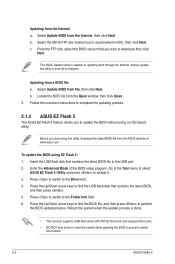
... the Internet. Press the Up/Down arrow keys to find the USB flash disk that contains the latest BIOS, and then press . 5. The ASUS Update utility is done. • This function supports USB flash disks with FAT 32/16 format and single partition only. • DO NOT...system while updating the BIOS to update the BIOS without using EZ Flash 2: 1. Insert the USB flash disk that you to prevent system boot failure! 2-2 ASUS F2A85-V c. Updating from file, then click Next. Updating from the Open window, then click Open. 3. Before you to the USB port. 2. b. Press ...
... the Internet. Press the Up/Down arrow keys to find the USB flash disk that contains the latest BIOS, and then press . 5. The ASUS Update utility is done. • This function supports USB flash disks with FAT 32/16 format and single partition only. • DO NOT...system while updating the BIOS to update the BIOS without using EZ Flash 2: 1. Insert the USB flash disk that you to prevent system boot failure! 2-2 ASUS F2A85-V c. Updating from file, then click Next. Updating from the Open window, then click Open. 3. Before you to the USB port. 2. b. Press ...
F2A85-V User's Manual
Page 50
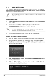
... drive). At the FreeDOS prompt, type d: and press to switch the disk from the ASUS website at http://support.asus.com and save the BIOS file and BIOS Updater to update BIOS in DOS environment. C:\>d: D:\> 2-4 ASUS F2A85-V 2.1.4 ASUS BIOS Updater The ASUS BIOS Updater allows you to a hard disk drive or USB flash drive in NTFS...
... drive). At the FreeDOS prompt, type d: and press to switch the disk from the ASUS website at http://support.asus.com and save the BIOS file and BIOS Updater to update BIOS in DOS environment. C:\>d: D:\> 2-4 ASUS F2A85-V 2.1.4 ASUS BIOS Updater The ASUS BIOS Updater allows you to a hard disk drive or USB flash drive in NTFS...

F2A85-V User's Manual
Page 52
... BIOS Setup program. BIOS menu screen The BIOS setup program can cause damage to your motherboard if you in the EZ Mode/Advanced Mode screen. 2-6 ASUS F2A85-V Refer to section 1.7 Jumpers on . Select the Load Optimized Defaults item under two modes: EZ Mode and Advanced Mode. Entering BIOS Setup at startup To...
... BIOS Setup program. BIOS menu screen The BIOS setup program can cause damage to your motherboard if you in the EZ Mode/Advanced Mode screen. 2-6 ASUS F2A85-V Refer to section 1.7 Jumpers on . Select the Load Optimized Defaults item under two modes: EZ Mode and Advanced Mode. Entering BIOS Setup at startup To...
F2A85-V User's Manual
Page 54
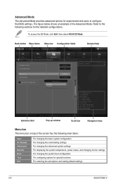
...below shows an example of the screen has the following sections for special functions For selecting the exit options and loading default settings 2-8 ASUS F2A85-V Pop-up window Scroll bar Navigation keys Menu bar The menu bar on top of the Advanced Mode. Advanced Mode General help Exit ...Defaults F10: Save ESC: Exit F12: Print Screen Submenu item Version 2.10.1208. To access the EZ Mode, click Exit, then select ASUS EZ Mode. Advanced Mode The Advanced Mode provides advanced options for experienced end-users to the following main items: Main Ai Tweaker Advanced Monitor ...
...below shows an example of the screen has the following sections for special functions For selecting the exit options and loading default settings 2-8 ASUS F2A85-V Pop-up window Scroll bar Navigation keys Menu bar The menu bar on top of the Advanced Mode. Advanced Mode General help Exit ...Defaults F10: Save ESC: Exit F12: Print Screen Submenu item Version 2.10.1208. To access the EZ Mode, click Exit, then select ASUS EZ Mode. Advanced Mode The Advanced Mode provides advanced options for experienced end-users to the following main items: Main Ai Tweaker Advanced Monitor ...
F2A85-V User's Manual
Page 56
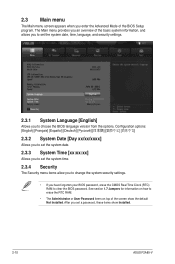
... The Security menu items allow you to change the system security settings. • If you enter the Advanced Mode of the screen show Installed. 2-10 ASUS F2A85-V Configuration options: [English] [Français] [Español] [Deutsch 2.3.2 System Date [Day xx/xx/xxxx] Allows you to set the system date. 2.3.3 System Time...
... The Security menu items allow you to change the system security settings. • If you enter the Advanced Mode of the screen show Installed. 2-10 ASUS F2A85-V Configuration options: [English] [Français] [Español] [Deutsch 2.3.2 System Date [Day xx/xx/xxxx] Allows you to set the system date. 2.3.3 System Time...


