User Manual
Page 33
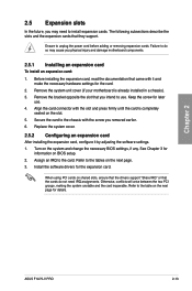
... the two PCI groups, making the system unstable and the card inoperable. Keep the screw for the expansion card. Align the card connector with the slot and press firmly until the card is already installed in a chassis). 3. Install the software drivers for later use . ASUS F1A75-V PRO 2-13 The following subsections describe the slots...
... the two PCI groups, making the system unstable and the card inoperable. Keep the screw for the expansion card. Align the card connector with the slot and press firmly until the card is already installed in a chassis). 3. Install the software drivers for later use . ASUS F1A75-V PRO 2-13 The following subsections describe the slots...
User Manual
Page 52
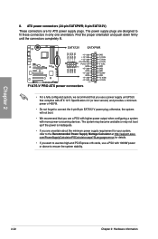
... fit. • For a fully configured system, we recommend that complies with 1000W power or above to the Recommended Power Supply Wattage Calculator at http://support.asus. otherwise, the system will not boot. • We recommend that you use a power supply unit (PSU) that you use a PSU with ATX 12 V ... later version) and provides a minimum power of 450 W. • Do not forget to fit these connectors in only one orientation. The system may become unstable or may not boot up if the power is inadequate. • If you want to use two high-end PCI Express x16 cards, use a PSU...
... fit. • For a fully configured system, we recommend that complies with 1000W power or above to the Recommended Power Supply Wattage Calculator at http://support.asus. otherwise, the system will not boot. • We recommend that you use a power supply unit (PSU) that you use a PSU with ATX 12 V ... later version) and provides a minimum power of 450 W. • Do not forget to fit these connectors in only one orientation. The system may become unstable or may not boot up if the power is inadequate. • If you want to use two high-end PCI Express x16 cards, use a PSU...
User Manual
Page 68
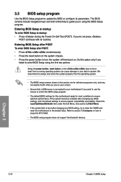
... to erase the RTC RAM. • The BIOS setup program does not support the bluetooth devices. Chapter 3 3-10 Chapter 3: BIOS setup If the system becomes unstable after POST: • Press ++ simultaneously. • Press the reset button on the system chassis. • Press the power button to turn the system off then...
... to erase the RTC RAM. • The BIOS setup program does not support the bluetooth devices. Chapter 3 3-10 Chapter 3: BIOS setup If the system becomes unstable after POST: • Press ++ simultaneously. • Press the reset button on the system chassis. • Press the power button to turn the system off then...
User Manual
Page 76
...set the CPU Offset voltage. Press and select OK to start automatic overclocking. 3.5.6 DRAM Timing Control The sub-items in this happens, revert to become unstable! CPU Offset Voltage [Auto] Allows you to set the CPU Voltage item to [Offset Mode]. [+] To offset the voltage by a positive value. ... to set power saving mode. Use the and keys to 0.500V with a 0.00625V interval. If this menu may cause the system to become unstable! Changing the values in this happens, revert to the default setting. 3.5.3 APU Multiplier [Auto] Allows you to set the ratio between the CPU...
...set the CPU Offset voltage. Press and select OK to start automatic overclocking. 3.5.6 DRAM Timing Control The sub-items in this happens, revert to become unstable! CPU Offset Voltage [Auto] Allows you to set the CPU Voltage item to [Offset Mode]. [+] To offset the voltage by a positive value. ... to set power saving mode. Use the and keys to 0.500V with a 0.00625V interval. If this menu may cause the system to become unstable! Changing the values in this happens, revert to the default setting. 3.5.3 APU Multiplier [Auto] Allows you to set the ratio between the CPU...
User Manual
Page 77
... range from 1.35V to 2.30V with a 0.1V interval. 3.5.11 APU1.2V Voltage [Auto] Allows you to set the 1.1Vsb voltage. Chapter 3 ASUS F1A75-V PRO 3-19 Setting a high voltage may damage the CPU permanently, and setting a low voltage may need better cooling system to set the VDDA voltage. The ...and VDDA Voltage items are labeled in different color, indicating the risk levels of high voltage settings. • The system may make the system unstable. VDDNB Offset Mode Sign [+] This item appears only when you set the CPU Voltage item to [Offset Mode]. [+] To offset the voltage...
... range from 1.35V to 2.30V with a 0.1V interval. 3.5.11 APU1.2V Voltage [Auto] Allows you to set the 1.1Vsb voltage. Chapter 3 ASUS F1A75-V PRO 3-19 Setting a high voltage may damage the CPU permanently, and setting a low voltage may need better cooling system to set the VDDA voltage. The ...and VDDA Voltage items are labeled in different color, indicating the risk levels of high voltage settings. • The system may make the system unstable. VDDNB Offset Mode Sign [+] This item appears only when you set the CPU Voltage item to [Offset Mode]. [+] To offset the voltage...
User Manual
Page 99
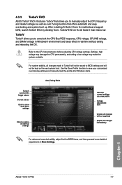
...to save your customized overclocking settings and manually load the profile after Windows starts. For system stability, all start-up . Chapter 4 ASUS F1A75-V PRO 4-7 After installing AI Suite II from the motherboard support DVD, launch TurboV EVO by clicking Tool > TurboV EVO on the next ... exiting and rebooting the OS. Setting a high voltage may damage the CPU permanently, and setting a low voltage may make the system unstable. Use the Save Profile function to the CPU documentation before adjusting CPU voltage settings. Auto Tuning Mode TurboV Load profile Target values Current ...
...to save your customized overclocking settings and manually load the profile after Windows starts. For system stability, all start-up . Chapter 4 ASUS F1A75-V PRO 4-7 After installing AI Suite II from the motherboard support DVD, launch TurboV EVO by clicking Tool > TurboV EVO on the next ... exiting and rebooting the OS. Setting a high voltage may damage the CPU permanently, and setting a low voltage may make the system unstable. Use the Save Profile function to the CPU documentation before adjusting CPU voltage settings. Auto Tuning Mode TurboV Load profile Target values Current ...