User Manual
Page 5
... 3.8.4 3.8.5 3.8.6 3.8.7 Option ROM Messages [Force BIOS 3-31 Setup Mode [EZ Mode 3-31 Boot Option Priorities 3-31 Boot Override 3-31 3.9 Tools menu 3-32 3.9.1 ASUS EZ Flash Utility 3-32 3.9.2 ASUS O.C. Profile 3-32 3.9.3 ASUS SPD Information 3-32 3.10 Exit menu 3-33 ... Installing an operating system 4-1 4.2 Support DVD information 4-1 4.2.1 Running the support DVD 4-1 4.2.2 Obtaining the software manuals 4-2 4.3 Software information 4-3 4.3.1 ASUS AI Suite II 4-3 4.3.2 DIGI+ VRM 4-4 4.3.3 TurboV EVO 4-7 4.3.4 EPU 4-11 4.3.5 FAN Xpert 4-12 4.3.6 Probe II 4-13 4.3.7 Ai...
... 3.8.4 3.8.5 3.8.6 3.8.7 Option ROM Messages [Force BIOS 3-31 Setup Mode [EZ Mode 3-31 Boot Option Priorities 3-31 Boot Override 3-31 3.9 Tools menu 3-32 3.9.1 ASUS EZ Flash Utility 3-32 3.9.2 ASUS O.C. Profile 3-32 3.9.3 ASUS SPD Information 3-32 3.10 Exit menu 3-33 ... Installing an operating system 4-1 4.2 Support DVD information 4-1 4.2.1 Running the support DVD 4-1 4.2.2 Obtaining the software manuals 4-2 4.3 Software information 4-3 4.3.1 ASUS AI Suite II 4-3 4.3.2 DIGI+ VRM 4-4 4.3.3 TurboV EVO 4-7 4.3.4 EPU 4-11 4.3.5 FAN Xpert 4-12 4.3.6 Probe II 4-13 4.3.7 Ai...
User Manual
Page 8
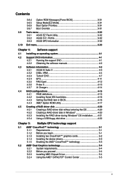
... are also provided. • Chapter 4: Software support This chapter describes the contents of the standard package. ASUS websites The ASUS website provides updated information on the motherboard. • Chapter 3: BIOS setup This chapter tells how to the ASUS contact information. 2. Optional documentation Your product package may have to perform when installing system components. viii...
... are also provided. • Chapter 4: Software support This chapter describes the contents of the standard package. ASUS websites The ASUS website provides updated information on the motherboard. • Chapter 3: BIOS setup This chapter tells how to the ASUS contact information. 2. Optional documentation Your product package may have to perform when installing system components. viii...
User Manual
Page 11
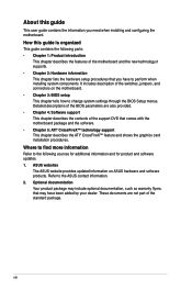
... ASUS Quiet Thermal Solutions - ASUS CrashFree BIOS 3 - EPU - TurboV - AI Suite II - AI Charger+ - ASUS Fan Xpert ASUS EZ DIY ASUS Q-Slot, Q-Shield, Q-Connector - Optical S/PDIF Out port at the back panel ASUS Dual Intelligent Processors 2 with DIGI+VRM: ASUS EPU - ASUS EZ Flash 2 - ASUS MyLogo 2™ - Multi-language BIOS (continued on the next page) xi F1A75-V PRO specifications summary LAN Audio USB ASUS...
... ASUS Quiet Thermal Solutions - ASUS CrashFree BIOS 3 - EPU - TurboV - AI Suite II - AI Charger+ - ASUS Fan Xpert ASUS EZ DIY ASUS Q-Slot, Q-Shield, Q-Connector - Optical S/PDIF Out port at the back panel ASUS Dual Intelligent Processors 2 with DIGI+VRM: ASUS EPU - ASUS EZ Flash 2 - ASUS MyLogo 2™ - Multi-language BIOS (continued on the next page) xi F1A75-V PRO specifications summary LAN Audio USB ASUS...

User Manual
Page 13
xiii BIOS features Support DVD contents Accessories Form factor 32Mb Flash ROM, UEFI BIOS, PnP, DMI2.0, WfM2.0, ACPI2.0a, SM BIOS 2.6, ASUS EZ Flash 2, ASUS CrashFree BIOS 3 Drivers ASUS Update ASUS utilities Anti-Virus software (OEM version) 2 x Serial ATA 6.0Gb/s cables 1 x 2-in-1 Q-connector (retail version only) 1 x Q-Shield 1 x User Manual 1 x Support DVD ATX form factor: 12.0 in x 9.6 in (30.5 cm x 24.4 cm) *Specifications are subject to change without notice.
xiii BIOS features Support DVD contents Accessories Form factor 32Mb Flash ROM, UEFI BIOS, PnP, DMI2.0, WfM2.0, ACPI2.0a, SM BIOS 2.6, ASUS EZ Flash 2, ASUS CrashFree BIOS 3 Drivers ASUS Update ASUS utilities Anti-Virus software (OEM version) 2 x Serial ATA 6.0Gb/s cables 1 x 2-in-1 Q-connector (retail version only) 1 x Q-Shield 1 x User Manual 1 x Support DVD ATX form factor: 12.0 in x 9.6 in (30.5 cm x 24.4 cm) *Specifications are subject to change without notice.
User Manual
Page 17
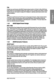
... mere push of two onboard chips - EPU Tap into a digital standard. ASUS UEFI BIOS (EZ Mode) The new ASUS UEFI BIOS, a user-friendly Unified Extensible Firmware Interface (UEFI), goes beyond the traditional-keyboard only BIOS input to patch memory issues. It features an onboard digital programmable microprocessor to ... delivery into the world's first real time PC power saving engine through the operating system's interface. Moreover, the ASUS OC profiles in different scenarios. Even O.C. You can automatically optimize the system for the experienced ASUS F1A75-V PRO 1-3
... mere push of two onboard chips - EPU Tap into a digital standard. ASUS UEFI BIOS (EZ Mode) The new ASUS UEFI BIOS, a user-friendly Unified Extensible Firmware Interface (UEFI), goes beyond the traditional-keyboard only BIOS input to patch memory issues. It features an onboard digital programmable microprocessor to ... delivery into the world's first real time PC power saving engine through the operating system's interface. Moreover, the ASUS OC profiles in different scenarios. Even O.C. You can automatically optimize the system for the experienced ASUS F1A75-V PRO 1-3
User Manual
Page 19
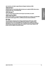
...your system. ASUS F1A75-V PRO 1-5 Chapter 1 static electricity and shields it against Electronic Magnetic Interference (EMI). This is European Union´s Energy-related Products (ErP) ready, and ErP requires products to meet certain energy efficiency requirements in line with ASUS vision of ...ASUS EZ Flash 2 ASUS EZ Flash 2 is an auto-recovery tool that allows you to restore a corrupted BIOS file using the bundled support DVD or a USB flash disk that allows you to energy consumptions. ASUS CrashFree BIOS 3 ASUS CrashFree BIOS 3 is a user-friendly utility that contains the BIOS...
...your system. ASUS F1A75-V PRO 1-5 Chapter 1 static electricity and shields it against Electronic Magnetic Interference (EMI). This is European Union´s Energy-related Products (ErP) ready, and ErP requires products to meet certain energy efficiency requirements in line with ASUS vision of ...ASUS EZ Flash 2 ASUS EZ Flash 2 is an auto-recovery tool that allows you to restore a corrupted BIOS file using the bundled support DVD or a USB flash disk that allows you to energy consumptions. ASUS CrashFree BIOS 3 ASUS CrashFree BIOS 3 is a user-friendly utility that contains the BIOS...
User Manual
Page 22
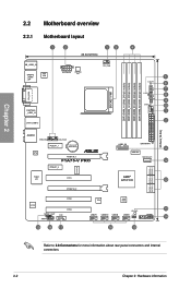
... TPU EPU 5 6 7 8 9 10 1 2 30.5cm(12.0in) AUDIO PWR_FAN CHA_FAN1 PCIEX1_1 Lithium Cell CMOS Power RTL 8111E PCIEX16_1 F1A75-V PRO PCIEX1_2 ICS477D Super I/O PCI1 PCIEX16_2 USB3_56 EATXPWR 11 ASM1061 SATA6G_E1 12 AMD® A75 FCH 12 SATA6G_2 SATA6G_4 SATA6G_6 SATA6G_1 SATA6G_3 SATA6G_5 ALC892 PCI2... SPDIF_OUT AAFP COM1 PCI3 19 18 17 TPU 32Mb BIOS USB78 USB910 USB34 SB_PWR USB56 CLRTC PANEL 13 14 16 15 Refer to 2.8 Connectors for more information about rear panel connectors...
... TPU EPU 5 6 7 8 9 10 1 2 30.5cm(12.0in) AUDIO PWR_FAN CHA_FAN1 PCIEX1_1 Lithium Cell CMOS Power RTL 8111E PCIEX16_1 F1A75-V PRO PCIEX1_2 ICS477D Super I/O PCI1 PCIEX16_2 USB3_56 EATXPWR 11 ASM1061 SATA6G_E1 12 AMD® A75 FCH 12 SATA6G_2 SATA6G_4 SATA6G_6 SATA6G_1 SATA6G_3 SATA6G_5 ALC892 PCI2... SPDIF_OUT AAFP COM1 PCI3 19 18 17 TPU 32Mb BIOS USB78 USB910 USB34 SB_PWR USB56 CLRTC PANEL 13 14 16 15 Refer to 2.8 Connectors for more information about rear panel connectors...
User Manual
Page 33
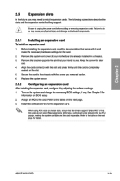
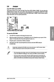
Ensure to the card. Secure the card to the chassis with it by adjusting the software settings. 1. Turn on BIOS setup. 2. Failure to do not need to install expansion cards. See Chapter 3 for later use . When using PCI cards on the slot. 5. Otherwise, ...settings for the card. 2. Assign an IRQ to unplug the power cord before adding or removing expansion cards. ASUS F1A75-V PRO 2-13 Keep the screw for information on the system and change the necessary BIOS settings, if any. Install the software drivers for details. Align the card connector with the slot and press...
Ensure to the card. Secure the card to the chassis with it by adjusting the software settings. 1. Turn on BIOS setup. 2. Failure to do not need to install expansion cards. See Chapter 3 for later use . When using PCI cards on the slot. 5. Otherwise, ...settings for the card. 2. Assign an IRQ to unplug the power cord before adding or removing expansion cards. ASUS F1A75-V PRO 2-13 Keep the screw for information on the system and change the necessary BIOS settings, if any. Install the software drivers for details. Align the card connector with the slot and press...
User Manual
Page 37
The onboard button cell battery powers the RAM data in CMOS. ASUS F1A75-V PRO 2-17 You can automatically reset parameter settings to overclocking. Turn OFF the computer and... the jumper again to clear the CMOS RTC RAM data. Shut down the key during the boot process and enter BIOS setup to re-enter data. Keep the cap on CLRTC jumper default position. Plug the power cord and turn ON... due to default values. To erase the RTC RAM: 1. Hold down and reboot the system so the BIOS can clear the CMOS memory of date, time, and system setup parameters by erasing the CMOS RTC RAM ...
The onboard button cell battery powers the RAM data in CMOS. ASUS F1A75-V PRO 2-17 You can automatically reset parameter settings to overclocking. Turn OFF the computer and... the jumper again to clear the CMOS RTC RAM data. Shut down the key during the boot process and enter BIOS setup to re-enter data. Keep the cap on CLRTC jumper default position. Plug the power cord and turn ON... due to default values. To erase the RTC RAM: 1. Hold down and reboot the system so the BIOS can clear the CMOS memory of date, time, and system setup parameters by erasing the CMOS RTC RAM ...
User Manual
Page 38
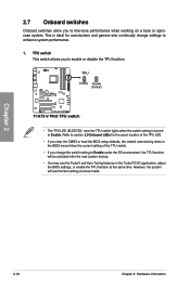
... setting to Enable under the OS environment, the TPU function will use the TurboV and Auto Tuning features in the TurboV EVO application, adjust the BIOS settings, or enable the TPU function at the same time. However, the system will be activated after the next system bootup. • You may ... switch setting is ideal for the exact location of the TPU LED. • If you clear the CMOS or load the BIOS setup defaults, the related overclocking items in the BIOS menu follow the current setting of the TPU switch. • If you change settings to enhance system performance. 1. TPU switch ...
... setting to Enable under the OS environment, the TPU function will use the TurboV and Auto Tuning features in the TurboV EVO application, adjust the BIOS settings, or enable the TPU function at the same time. However, the system will be activated after the next system bootup. • You may ... switch setting is ideal for the exact location of the TPU LED. • If you clear the CMOS or load the BIOS setup defaults, the related overclocking items in the BIOS menu follow the current setting of the TPU switch. • If you change settings to enhance system performance. 1. TPU switch ...

User Manual
Page 39
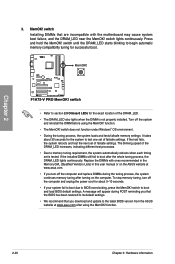
... be activated after the next system bootup. • You may change the EPU settings in the EPU application, change the BIOS settings, and enable the EPU function at the same time. Chapter 2 ASUS F1A75-V PRO 2-19 Refer to Enable. EPU switch This switch allows you to enable or disable the EPU function. • The...
... be activated after the next system bootup. • You may change the EPU settings in the EPU application, change the BIOS settings, and enable the EPU function at the same time. Chapter 2 ASUS F1A75-V PRO 2-19 Refer to Enable. EPU switch This switch allows you to enable or disable the EPU function. • The...
User Manual
Page 40
..., the system loads and tests failsafe memory settings. function. 2-20 Chapter 2: Hardware information If the installed DIMMs still fail to the latest BIOS version from the ASUS website at www.asus.com. • If you turn off the computer and unplug the power cord for successful boot. switch to begin automatic memory compatibility...
..., the system loads and tests failsafe memory settings. function. 2-20 Chapter 2: Hardware information If the installed DIMMs still fail to the latest BIOS version from the ASUS website at www.asus.com. • If you turn off the computer and unplug the power cord for successful boot. switch to begin automatic memory compatibility...
User Manual
Page 41
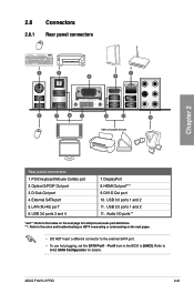
...to 3.4.2 SATA Configuration for LAN port and audio port definitions. ***: Refer to [AHCI]. External SATA port 5. USB 3.0 ports 1 and 2 11. ASUS F1A75-V PRO 2-21 Optical S/PDIF Out port 3. LAN (RJ-45) port* 6. DVI-D Out port 10. 2.8 Connectors 2.8.1 Rear panel connectors Chapter 2 Rear ...panel connectors 1. PS/2 keyboard/Mouse Combo port 2. Port4 item in the BIOS to the notes and troubleshooting on HDTV overscaling or underscaling on the next page for details. HDMI Out port*** 9. USB 3.0 ports 3 ...
...to 3.4.2 SATA Configuration for LAN port and audio port definitions. ***: Refer to [AHCI]. External SATA port 5. USB 3.0 ports 1 and 2 11. ASUS F1A75-V PRO 2-21 Optical S/PDIF Out port 3. LAN (RJ-45) port* 6. DVI-D Out port 10. 2.8 Connectors 2.8.1 Rear panel connectors Chapter 2 Rear ...panel connectors 1. PS/2 keyboard/Mouse Combo port 2. Port4 item in the BIOS to the notes and troubleshooting on HDTV overscaling or underscaling on the next page for details. HDMI Out port*** 9. USB 3.0 ports 3 ...
User Manual
Page 43
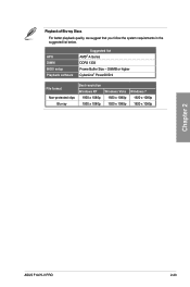
Playback of Blu-ray Discs For better playback quality, we suggest that you follow the system requirements in the suggested list below. APU DIMM BIOS setup Playback software Suggested list AMD® A-Series DDR3 1333 Frame Buffer Size - 256MB or higher CyberLink® PowerDVD 9 File format Non-protected clips Blu-ray Best resolution Windows XP 1920 x 1080p 1920 x 1080p Windows Vista 1920 x 1080p 1920 x 1080p Windows 7 1920 x 1080p 1920 x 1080p Chapter 2 ASUS F1A75-V PRO 2-23
Playback of Blu-ray Discs For better playback quality, we suggest that you follow the system requirements in the suggested list below. APU DIMM BIOS setup Playback software Suggested list AMD® A-Series DDR3 1333 Frame Buffer Size - 256MB or higher CyberLink® PowerDVD 9 File format Non-protected clips Blu-ray Best resolution Windows XP 1920 x 1080p 1920 x 1080p Windows Vista 1920 x 1080p 1920 x 1080p Windows 7 1920 x 1080p 1920 x 1080p Chapter 2 ASUS F1A75-V PRO 2-23

User Manual
Page 47
... connect Serial ATA boot/data hard disk drives to [AHCI] in the BIOS. If you installed Serial ATA hard disk drives, you are for the Serial ATA 6.0 Gb/s signal cables for Serial ATA hard disk drives and optical disc drives. ASUS F1A75-V PRO 2-27 SATA Serial ATA 6.0 Gb/s connectors (7-pin SATA6G_E1, SATA6G_1~6) These connectors... for details. • You must install Windows® XP Service Pack 3 or later version before using hot-plug and NCQ, set to [RAID] in the BIOS.
... connect Serial ATA boot/data hard disk drives to [AHCI] in the BIOS. If you installed Serial ATA hard disk drives, you are for the Serial ATA 6.0 Gb/s signal cables for Serial ATA hard disk drives and optical disc drives. ASUS F1A75-V PRO 2-27 SATA Serial ATA 6.0 Gb/s connectors (7-pin SATA6G_E1, SATA6G_1~6) These connectors... for details. • You must install Windows® XP Service Pack 3 or later version before using hot-plug and NCQ, set to [RAID] in the BIOS.
User Manual
Page 51
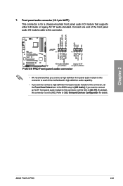
... Devices Configuration for a chassis-mounted front panel audio I /O module cable to this connector, set the item to [HD]. Chapter 2 ASUS F1A75-V PRO 2-31 By default, this connector, set the Front Panel Select item in the BIOS setup to this connector. • We recommend that supports either HD Audio or legacy AC`97 audio standard. 7.
... Devices Configuration for a chassis-mounted front panel audio I /O module cable to this connector, set the item to [HD]. Chapter 2 ASUS F1A75-V PRO 2-31 By default, this connector, set the Front Panel Select item in the BIOS setup to this connector. • We recommend that supports either HD Audio or legacy AC`97 audio standard. 7.
User Manual
Page 57
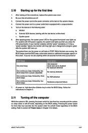
...component failure 7. Turn on the screen. Monitor b. For systems with a surge protector. 5. If you do not see the BIOS beep codes table below) or additional messages appear on the devices in Chapter 3. 2.11 Turning off mode regardless of the system...computer While the system is equipped with ATX power supplies, the system LED lights up when you turned on BIOS Beep One short beep One continuous beep followed by two short beeps then a pause (repeated) One continuous beep... LED may light up or change from the time you press the ATX power button. ASUS F1A75-V PRO 2-37
...component failure 7. Turn on the screen. Monitor b. For systems with a surge protector. 5. If you do not see the BIOS beep codes table below) or additional messages appear on the devices in Chapter 3. 2.11 Turning off mode regardless of the system...computer While the system is equipped with ATX power supplies, the system LED lights up when you turned on BIOS Beep One short beep One continuous beep followed by two short beeps then a pause (repeated) One continuous beep... LED may light up or change from the time you press the ATX power button. ASUS F1A75-V PRO 2-37
User Manual
Page 59
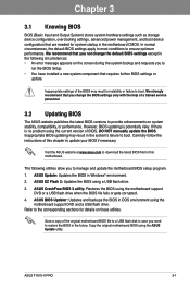
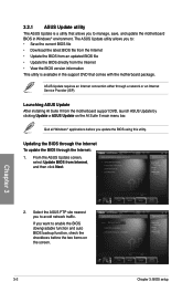
... in the system's failure to manage and update the motherboard BIOS setup program. 1. If there is potentially risky. ASUS Update: Updates the BIOS in DOS environment using the motherboard support DVD and a USB flash drive. ASUS BIOS Updater: Updates and backups the BIOS in Windows® environment. 2. Chapter 3 ASUS F1A75-V PRO 3-1 Carefully follow the instructions of the original motherboard...
... in the system's failure to manage and update the motherboard BIOS setup program. 1. If there is potentially risky. ASUS Update: Updates the BIOS in DOS environment using the motherboard support DVD and a USB flash drive. ASUS BIOS Updater: Updates and backups the BIOS in Windows® environment. 2. Chapter 3 ASUS F1A75-V PRO 3-1 Carefully follow the instructions of the original motherboard...
User Manual
Page 60
... information This utility is a utility that comes with the motherboard package. From the ASUS Update screen, select Update BIOS from the motherboard support DVD, launch ASUS Update by clicking Update > ASUS Update on the screen. 3-2 Chapter 3: BIOS setup Quit all Windows® applications before the two items on the AI Suite II main menu bar...
... information This utility is a utility that comes with the motherboard package. From the ASUS Update screen, select Update BIOS from the motherboard support DVD, launch ASUS Update by clicking Update > ASUS Update on the screen. 3-2 Chapter 3: BIOS setup Quit all Windows® applications before the two items on the AI Suite II main menu bar...
User Manual
Page 61
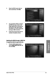
3. Updating the BIOS through a BIOS file To update the BIOS through a BIOS file: 1. Chapter 3 ASUS F1A75-V PRO 3-3 Click Yes if you want to download. From the ASUS Update screen, select Update BIOS from file, and then click Next. Select the BIOS version that you want to change the BIOS boot logo, which is the image appearing on screen during the Power‑On Self-Tests (POST). Follow the onscreen instructions to continue. 5. You can decide whether to change the boot logo or No to complete the update process. Click Next. 4.
3. Updating the BIOS through a BIOS file To update the BIOS through a BIOS file: 1. Chapter 3 ASUS F1A75-V PRO 3-3 Click Yes if you want to download. From the ASUS Update screen, select Update BIOS from file, and then click Next. Select the BIOS version that you want to change the BIOS boot logo, which is the image appearing on screen during the Power‑On Self-Tests (POST). Follow the onscreen instructions to continue. 5. You can decide whether to change the boot logo or No to complete the update process. Click Next. 4.


