F1A55 R2.0 User's Manual
Page 12
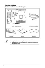
xii DRAM_LED EATXPWR ASUS F1A55 R2.0 motherboard User Manual 2 x Serial ATA 3.0 Gb/s cables 1 x I/O-Shield User Guide Support DVD • If any of the above are for the following items. KBMS USB56 ... USB3_E12 LAN1_USB12 AUDIO Realtek® 8111E Super I/O ALC 887 AAFP ATX12V CHA_FAN1 PWR_FAN PCIEX1_1 PCIEX1_2 PCI3 COM1 SPDIF_OUT CPU_FAN EPU Lithium Cell CMOS Power PCIEX16_1 F1A55 R2.0 PCI1 PCIEX16_2 PCI2 USB1112 USB910 64Mb BIOS USB78 CHA_FAN2 CLRTC SB_PWR PANEL SATA3G_1 SATA3G_2 AMD® A55 FCH ICS483A SATA3G_3 SATA3G_5 SATA3G_4 SATA3G_6 SOCKET FM1...
xii DRAM_LED EATXPWR ASUS F1A55 R2.0 motherboard User Manual 2 x Serial ATA 3.0 Gb/s cables 1 x I/O-Shield User Guide Support DVD • If any of the above are for the following items. KBMS USB56 ... USB3_E12 LAN1_USB12 AUDIO Realtek® 8111E Super I/O ALC 887 AAFP ATX12V CHA_FAN1 PWR_FAN PCIEX1_1 PCIEX1_2 PCI3 COM1 SPDIF_OUT CPU_FAN EPU Lithium Cell CMOS Power PCIEX16_1 F1A55 R2.0 PCI1 PCIEX16_2 PCI2 USB1112 USB910 64Mb BIOS USB78 CHA_FAN2 CLRTC SB_PWR PANEL SATA3G_1 SATA3G_2 AMD® A55 FCH ICS483A SATA3G_3 SATA3G_5 SATA3G_4 SATA3G_6 SOCKET FM1...
F1A55 R2.0 User's Manual
Page 13
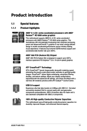
... 3D settings, and check the effects with AMD® Radeon™ HD 6000 series graphics This motherboard supports AMD® A- & E2- the latest connectivity standard. ASUS F1A55 R2.0 1-1 Built to connect easily with next-generation components and peripherals, USB 3.0 transfers data 10x faster and is designed to support up to 5GT/s interface speed...
... 3D settings, and check the effects with AMD® Radeon™ HD 6000 series graphics This motherboard supports AMD® A- & E2- the latest connectivity standard. ASUS F1A55 R2.0 1-1 Built to connect easily with next-generation components and peripherals, USB 3.0 transfers data 10x faster and is designed to support up to 5GT/s interface speed...
F1A55 R2.0 User's Manual
Page 15
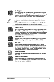
... *** The actual charging speed may vary with the ASUS TurboV. ASUS CrashFree BIOS 3 ASUS CrashFree BIOS 3 is a unique fast-charging software which supports iPods, iPhones and iPads. ** Check your PC's loading. ASUS F1A55 R2.0 1-3 ASUS TurboV Feel the adrenaline rush of USB3.0 fast charging... experience. Moreover, the ASUS OC profiles in different scenarios. ASUS MyLogo 2™ Personalize your system by different climate conditions in variety...
... *** The actual charging speed may vary with the ASUS TurboV. ASUS CrashFree BIOS 3 ASUS CrashFree BIOS 3 is a unique fast-charging software which supports iPods, iPhones and iPads. ** Check your PC's loading. ASUS F1A55 R2.0 1-3 ASUS TurboV Feel the adrenaline rush of USB3.0 fast charging... experience. Moreover, the ASUS OC profiles in different scenarios. ASUS MyLogo 2™ Personalize your system by different climate conditions in variety...
F1A55 R2.0 User's Manual
Page 17
... injury and damage motherboard components. 1.3.1 Placement direction When installing the motherboard, place it on a grounded antistatic pad or in the bag that the motherboard fits. ASUS F1A55 R2.0 1-5
... injury and damage motherboard components. 1.3.1 Placement direction When installing the motherboard, place it on a grounded antistatic pad or in the bag that the motherboard fits. ASUS F1A55 R2.0 1-5
F1A55 R2.0 User's Manual
Page 21
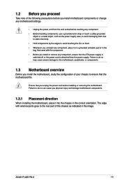
... Unplug all power cables before installing the CPU. • Upon purchase of the PnP cap. F1A55 R2.0 F1A55 R2.0 CPU socket FM1 2. Use an APU designed for AMD® Fusion™ A- & E2- ASUS will shoulder the cost of repair only if the damage is shipment/ transit-related. • Keep...Locate the FM1 socket on the socket and the socket contacts are not bent. Socket lever ASUS F1A55 R2.0 1-9 Contact your retailer immediately if the PnP cap is on the motherboard. ASUS will process Return Merchandise Authorization (RMA) requests only if the motherboard comes with the cap ...
... Unplug all power cables before installing the CPU. • Upon purchase of the PnP cap. F1A55 R2.0 F1A55 R2.0 CPU socket FM1 2. Use an APU designed for AMD® Fusion™ A- & E2- ASUS will shoulder the cost of repair only if the damage is shipment/ transit-related. • Keep...Locate the FM1 socket on the socket and the socket contacts are not bent. Socket lever ASUS F1A55 R2.0 1-9 Contact your retailer immediately if the PnP cap is on the motherboard. ASUS will process Return Merchandise Authorization (RMA) requests only if the motherboard comes with the cap ...
F1A55 R2.0 User's Manual
Page 23
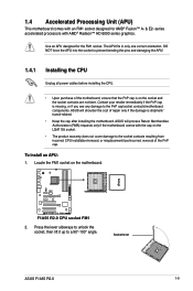
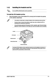
ASUS F1A55 R2.0 1-11 1.4.2 Installing the heatsink and fan Use only AMD-certified heatsink and fan assemblies. If the instructions in this section do not have to remove ...
ASUS F1A55 R2.0 1-11 1.4.2 Installing the heatsink and fan Use only AMD-certified heatsink and fan assemblies. If the instructions in this section do not have to remove ...
F1A55 R2.0 User's Manual
Page 25
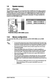
... the location of the DDR3 DIMM sockets: DIMM_A1 DIMM_A2 DIMM_B1 DIMM_B2 Channel Channel A Channel B Sockets DIMM_A1 and DIMM_A2 DIMM_B1 and DIMM_B2 F1A55 R2.0 F1A55 R2.0 240-pin DDR3 DIMM sockets 1.5.2 Memory configurations You may install 1GB, 2GB, and 4GB unbuffered non-ECC DDR3 DIMMs into the DIMM... OS can be about 3GB or less. For effective use of memory, we recommend that you want to prevent installation on the motherboard. ASUS F1A55 R2.0 1-13 A DDR3 module has the same physical dimensions as a DDR2 DIMM but is then mapped for single-channel operation. •...
... the location of the DDR3 DIMM sockets: DIMM_A1 DIMM_A2 DIMM_B1 DIMM_B2 Channel Channel A Channel B Sockets DIMM_A1 and DIMM_A2 DIMM_B1 and DIMM_B2 F1A55 R2.0 F1A55 R2.0 240-pin DDR3 DIMM sockets 1.5.2 Memory configurations You may install 1GB, 2GB, and 4GB unbuffered non-ECC DDR3 DIMMs into the DIMM... OS can be about 3GB or less. For effective use of memory, we recommend that you want to prevent installation on the motherboard. ASUS F1A55 R2.0 1-13 A DDR3 module has the same physical dimensions as a DDR2 DIMM but is then mapped for single-channel operation. •...
F1A55 R2.0 User's Manual
Page 27
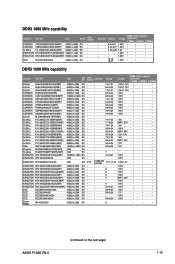
... 1.65V • • • - - 8-8-8-24 1.7V • • • - - - 1.65V • • • - - 8-8-8-24 1.65V • • - - 9 - • • • (continued on the next page) ASUS F1A55 R2.0 1-15 Size SS/ DS A-Data AX3U1600XB2G79-2X(XMP) A-Data AX3U1600GC4G9-2G(XMP) A-Data AX3U1600XC4G79-2X(XMP) CORSAIR TR3X3G1600C8D(XMP) CORSAIR CMD12GX3M6A1600C8(XMP) CORSAIR CMP4GX3M2C1600C7(XMP...
... 1.65V • • • - - 8-8-8-24 1.7V • • • - - - 1.65V • • • - - 8-8-8-24 1.65V • • - - 9 - • • • (continued on the next page) ASUS F1A55 R2.0 1-15 Size SS/ DS A-Data AX3U1600XB2G79-2X(XMP) A-Data AX3U1600GC4G9-2G(XMP) A-Data AX3U1600XC4G79-2X(XMP) CORSAIR TR3X3G1600C8D(XMP) CORSAIR CMD12GX3M6A1600C8(XMP) CORSAIR CMP4GX3M2C1600C7(XMP...
F1A55 R2.0 User's Manual
Page 29
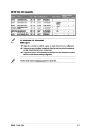
...1GB SS 2GB DS Micron Micron ELPIDA ELPIDA ELPIDA ELPIDA Hynix Micron Micron 9GF22D9KPT 7 9HF22D9KPT 7 J1108EDSE-DJ-F - ASUS F1A55 R2.0 1-17 Crucial Crucial ELPIDA CT12864BA1067.8FF CT25664BA1067.16FF EBJ10UE8EDF0-AE-F ELPIDA EBJ21UE8EDF0-AE-F KINGSTON KVR1066D3N7/1G(low profile)... KINGSTON KVR1066D3N7/2G KINGSTON KVR1066D3N7/4G Micron MT8JTF12864AZ-1G1F1 Micron MT16JTF25664AZ-1G1F1 Size SS/DS Chip Brand Chip NO. Visit the ASUS website at www.asus.com for the latest QVL. DIMM socket support (Optional) 1 DIMM 2 DIMMs 4 DIMMs • • • &#...
...1GB SS 2GB DS Micron Micron ELPIDA ELPIDA ELPIDA ELPIDA Hynix Micron Micron 9GF22D9KPT 7 9HF22D9KPT 7 J1108EDSE-DJ-F - ASUS F1A55 R2.0 1-17 Crucial Crucial ELPIDA CT12864BA1067.8FF CT25664BA1067.16FF EBJ10UE8EDF0-AE-F ELPIDA EBJ21UE8EDF0-AE-F KINGSTON KVR1066D3N7/1G(low profile)... KINGSTON KVR1066D3N7/2G KINGSTON KVR1066D3N7/4G Micron MT8JTF12864AZ-1G1F1 Micron MT16JTF25664AZ-1G1F1 Size SS/DS Chip Brand Chip NO. Visit the ASUS website at www.asus.com for the latest QVL. DIMM socket support (Optional) 1 DIMM 2 DIMMs 4 DIMMs • • • &#...
F1A55 R2.0 User's Manual
Page 31
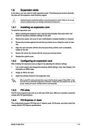
... support. Failure to do not need to the chassis with the PCI Express specifications. Align the card connector with it by adjusting the software settings. 1. ASUS F1A55 R2.0 1-19 Turn on the slot. 5. See Chapter 2 for the expansion card. Secure the card to install expansion cards. Install the software drivers for information on...
... support. Failure to do not need to the chassis with the PCI Express specifications. Align the card connector with it by adjusting the software settings. 1. ASUS F1A55 R2.0 1-19 Turn on the slot. 5. See Chapter 2 for the expansion card. Secure the card to install expansion cards. Install the software drivers for information on...
F1A55 R2.0 User's Manual
Page 33
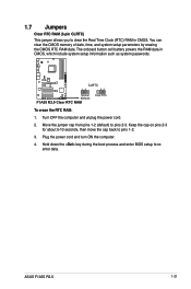
... ON the computer. 4. Hold down the key during the boot process and enter BIOS setup to pins 1-2. 3. ASUS F1A55 R2.0 1-21 Move the jumper cap from pins 1-2 (default) to pins 2-3. F1A55 R2.0 CLRTC 12 23 Normal (Default) F1A55 R2.0 Clear RTC RAM Clear RTC To erase the RTC RAM: 1. The onboard button cell battery powers the RAM...
... ON the computer. 4. Hold down the key during the boot process and enter BIOS setup to pins 1-2. 3. ASUS F1A55 R2.0 1-21 Move the jumper cap from pins 1-2 (default) to pins 2-3. F1A55 R2.0 CLRTC 12 23 Normal (Default) F1A55 R2.0 Clear RTC RAM Clear RTC To erase the RTC RAM: 1. The onboard button cell battery powers the RAM...
F1A55 R2.0 User's Manual
Page 35
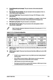
... after USB 3.0 driver installation. • USB 3.0 devices can only be used for the function of this port becomes Front Speaker Out. 7. Line Out port (lime). ASUS F1A55 R2.0 1-23 Refer to the tape, CD, DVD player, or other audio sources. 6. This port connects to a microphone. 8. This port connects to the audio configuration table...
... after USB 3.0 driver installation. • USB 3.0 devices can only be used for the function of this port becomes Front Speaker Out. 7. Line Out port (lime). ASUS F1A55 R2.0 1-23 Refer to the tape, CD, DVD player, or other audio sources. 6. This port connects to a microphone. 8. This port connects to the audio configuration table...
F1A55 R2.0 User's Manual
Page 37
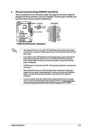
...inadequate. • DO NOT forget to install additional devices. com/PowerSupplyCalculator/PSCalculator.aspx?SLanguage=en-us for an ATX power supply. ATX12V EATXPWR F1A55 R2.0 GND GND PIN 1 +12V DC +3 Volts +12V DC +12 Volts +12 Volts +5V Standby Power OK GND +5 Volts GND +5 ...Volts GND +3 Volts +3 Volts PIN 1 F1A55 R2.0 ATX power connectors GND +5 Volts +5 Volts +5 Volts -5 Volts GND GND GND PSON# GND -12 Volts +3 Volts • We recommend that you intend to connect the 4-pin ATX +12V power plug. ASUS F1A55 R2.0 1-25 2.
...inadequate. • DO NOT forget to install additional devices. com/PowerSupplyCalculator/PSCalculator.aspx?SLanguage=en-us for an ATX power supply. ATX12V EATXPWR F1A55 R2.0 GND GND PIN 1 +12V DC +3 Volts +12V DC +12 Volts +12 Volts +5V Standby Power OK GND +5 Volts GND +5 ...Volts GND +3 Volts +3 Volts PIN 1 F1A55 R2.0 ATX power connectors GND +5 Volts +5 Volts +5 Volts -5 Volts GND GND GND PSON# GND -12 Volts +3 Volts • We recommend that you intend to connect the 4-pin ATX +12V power plug. ASUS F1A55 R2.0 1-25 2.
F1A55 R2.0 User's Manual
Page 39
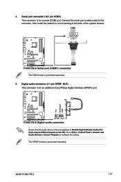
... cable to this connector, then install the module to configure the setting. COM1 PIN 1 F1A55 R2.0 F1A55 R2.0 Serial port (COM1) connector The COM module is purchased separately. +5V SPDIFOUT GND ASUS F1A55 R2.0 1-27 The S/PDIF module is purchased separately. 5. F1A55 R2.0 SPDIF_OUT F1A55 R2.0 Digital audio connector Ensure that the audio device of the system chassis. RXD DTR DSR...
... cable to this connector, then install the module to configure the setting. COM1 PIN 1 F1A55 R2.0 F1A55 R2.0 Serial port (COM1) connector The COM module is purchased separately. +5V SPDIFOUT GND ASUS F1A55 R2.0 1-27 The S/PDIF module is purchased separately. 5. F1A55 R2.0 SPDIF_OUT F1A55 R2.0 Digital audio connector Ensure that the audio device of the system chassis. RXD DTR DSR...
F1A55 R2.0 User's Manual
Page 41
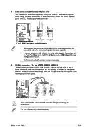
... USB_P10USB_P10+ GND NC USB+5V USB_P12USB_P12+ GND NC F1A55 R2.0 PIN 1 PIN 1 PIN 1 USB+5V USB_P7USB_P7+ GND USB+5V USB_P9USB_P9+ GND USB+5V USB_P11USB_P11+ GND F1A55 R2.0 USB2.0 connectors Never connect a 1394 cable to 480Mbps connection speed. ASUS F1A55 R2.0 1-29 7. USB 2.0 connectors (10-1 pin ...MIC2 MICPWR Line out_R NC Line out_L PORT1 L PORT1 R PORT2 R SENSE_SEND PORT2 L F1A55 R2.0 AAFP PIN 1 HD-audio-compliant Legacy AC'97 pin definition compliant definition F1A55 R2.0 Front panel audio connector • We recommend that supports either a High Definition Audio...
... USB_P10USB_P10+ GND NC USB+5V USB_P12USB_P12+ GND NC F1A55 R2.0 PIN 1 PIN 1 PIN 1 USB+5V USB_P7USB_P7+ GND USB+5V USB_P9USB_P9+ GND USB+5V USB_P11USB_P11+ GND F1A55 R2.0 USB2.0 connectors Never connect a 1394 cable to 480Mbps connection speed. ASUS F1A55 R2.0 1-29 7. USB 2.0 connectors (10-1 pin ...MIC2 MICPWR Line out_R NC Line out_L PORT1 L PORT1 R PORT2 R SENSE_SEND PORT2 L F1A55 R2.0 AAFP PIN 1 HD-audio-compliant Legacy AC'97 pin definition compliant definition F1A55 R2.0 Front panel audio connector • We recommend that supports either a High Definition Audio...
F1A55 R2.0 User's Manual
Page 43
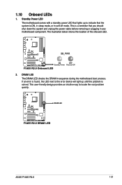
The illustration below shows the location of the onboard LED. F1A55 R2.0 DRAM LED F1A55 R2.0 DRAM LED ASUS F1A55 R2.0 1-31 F1A55 R2.0 SB_PWR ON OFF Standby Power Powered Off F1A55 R2.0 Onboard LED 2. If an error is solved. This user-friendly design provides an intuitive way to the error device will light up to indicate that ...
The illustration below shows the location of the onboard LED. F1A55 R2.0 DRAM LED F1A55 R2.0 DRAM LED ASUS F1A55 R2.0 1-31 F1A55 R2.0 SB_PWR ON OFF Standby Power Powered Off F1A55 R2.0 Onboard LED 2. If an error is solved. This user-friendly design provides an intuitive way to the error device will light up to indicate that ...
F1A55 R2.0 User's Manual
Page 45
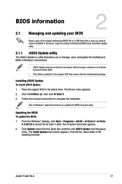
... package. The AI Suite II Quick Bar appears. 2. BIOS information 2.1 Managing and updating your BIOS 2 Save a copy of the following methods: ASUS F1A55 R2.0 2-1 From the Windows® desktop, click Start > Programs > ASUS > AI Suite II > AI Suite II X.XX.XX to manage, save, and update the motherboard BIOS in Windows® environment. •...
... package. The AI Suite II Quick Bar appears. 2. BIOS information 2.1 Managing and updating your BIOS 2 Save a copy of the following methods: ASUS F1A55 R2.0 2-1 From the Windows® desktop, click Start > Programs > ASUS > AI Suite II > AI Suite II X.XX.XX to manage, save, and update the motherboard BIOS in Windows® environment. •...
F1A55 R2.0 User's Manual
Page 47
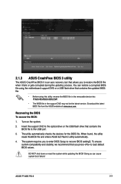
...the devices for the BIOS file. To ensure system compatibility and stability, we recommend that you press to the USB port. 3. ASUS F1A55 R2.0 2-3 2.1.3 ASUS CrashFree BIOS 3 utility The ASUS CrashFree BIOS 3 is an auto recovery tool that allows you to recover BIOS settingS. The system requires you to enter BIOS Setup... flash drive that contains the updated BIOS file. • Before using this utility, rename the BIOS file in the removable device into F1A55-R2-ASUS-0309.CAP. • The BIOS file in the support DVD may not be the latest version. You can cause system boot failure!
...the devices for the BIOS file. To ensure system compatibility and stability, we recommend that you press to the USB port. 3. ASUS F1A55 R2.0 2-3 2.1.3 ASUS CrashFree BIOS 3 utility The ASUS CrashFree BIOS 3 is an auto recovery tool that allows you to recover BIOS settingS. The system requires you to enter BIOS Setup... flash drive that contains the updated BIOS file. • Before using this utility, rename the BIOS file in the removable device into F1A55-R2-ASUS-0309.CAP. • The BIOS file in the support DVD may not be the latest version. You can cause system boot failure!
F1A55 R2.0 User's Manual
Page 49
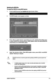
F1A55 R2.0 0309 F1A55-R2-ASUS-0309.CAP 8194 2012-05-16 15:25:48 3. BIOS Updater checks the selected BIOS file and prompts you to connect all SATA hard disk ... exits to the DOS prompt after updating the BIOS file if you have disconnected them. Select the Load Optimized Defaults item under the Exit menu. ASUS F1A55 R2.0 2-5 At the FreeDOS prompt, type bupdater /pc /g and press . 2. Select Yes and press . When BIOS update is done, press to ensure system compatibility and stability...
F1A55 R2.0 0309 F1A55-R2-ASUS-0309.CAP 8194 2012-05-16 15:25:48 3. BIOS Updater checks the selected BIOS file and prompts you to connect all SATA hard disk ... exits to the DOS prompt after updating the BIOS file if you have disconnected them. Select the Load Optimized Defaults item under the Exit menu. ASUS F1A55 R2.0 2-5 At the FreeDOS prompt, type bupdater /pc /g and press . 2. Select Yes and press . When BIOS update is done, press to ensure system compatibility and stability...
F1A55 R2.0 User's Manual
Page 51
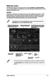
..., or enters the Advanced Mode Selects the boot device priority Displays the system properties of the basic system information, and allows you to the system. ASUS F1A55 R2.0 2-7 The EZ Mode provides you an overview of the selected mode on the right hand side Silent mode Standard mode Selects the boot device priority...
..., or enters the Advanced Mode Selects the boot device priority Displays the system properties of the basic system information, and allows you to the system. ASUS F1A55 R2.0 2-7 The EZ Mode provides you an overview of the selected mode on the right hand side Silent mode Standard mode Selects the boot device priority...


