User Manual
Page 3
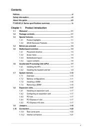
Contents Notices...vi Safety information vii About this guide viii F1A55-M LX Series specifications summary ix Chapter 1: Product introduction 1.1 Welcome 1-1 1.2 Package contents 1-1 1.3 Special features 1-1 1.3.1 Product highlights 1-1 1.3.2 ASUS Exclusive Features 1-2 1.4 Before you proceed 1-4 1.5 Motherboard overview 1-5 1.5.1 Placement direction 1-5 1.5.2 Screw holes 1-5 1.5.3 Motherboard layout 1-6 1.5.4 Layout contents 1-6 1.6 Accelerated Processing Unit (APU 1-7 1.6.1 Installing the APU 1-7 1.6.2 Installing the heatsink and fan 1-9 1.7 System...
Contents Notices...vi Safety information vii About this guide viii F1A55-M LX Series specifications summary ix Chapter 1: Product introduction 1.1 Welcome 1-1 1.2 Package contents 1-1 1.3 Special features 1-1 1.3.1 Product highlights 1-1 1.3.2 ASUS Exclusive Features 1-2 1.4 Before you proceed 1-4 1.5 Motherboard overview 1-5 1.5.1 Placement direction 1-5 1.5.2 Screw holes 1-5 1.5.3 Motherboard layout 1-6 1.5.4 Layout contents 1-6 1.6 Accelerated Processing Unit (APU 1-7 1.6.1 Installing the APU 1-7 1.6.2 Installing the heatsink and fan 1-9 1.7 System...
User Manual
Page 17
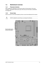
Place this side towards the rear of the chassis as indicated in the correct orientation. F1A55-M LX PLUS ASUS F1A55-M LX Series 1-5 DO NOT overtighten the screws! 1.5 Motherboard overview 1.5.1 Placement direction When installing the motherboard, ensure that you place it into the chassis in the image below. 1.5.2 Screw holes Place six screws into the holes indicated by circles to secure the motherboard to the rear part of the chassis. Doing so can damage the motherboard. The edge with external ports goes to the chassis.
Place this side towards the rear of the chassis as indicated in the correct orientation. F1A55-M LX PLUS ASUS F1A55-M LX Series 1-5 DO NOT overtighten the screws! 1.5 Motherboard overview 1.5.1 Placement direction When installing the motherboard, ensure that you place it into the chassis in the image below. 1.5.2 Screw holes Place six screws into the holes indicated by circles to secure the motherboard to the rear part of the chassis. Doing so can damage the motherboard. The edge with external ports goes to the chassis.

User Manual
Page 28
Firmly insert the DIMM into a socket in only one direction. The DIMM might get damaged when it fits in the wrong direction to both the motherboard and the components. 1. Align a DIMM on the socket. 2 DIMM notch 1 1 Unlocked retaining clip DIMM slot key A DIMM is properly seated. DO ...
Firmly insert the DIMM into a socket in only one direction. The DIMM might get damaged when it fits in the wrong direction to both the motherboard and the components. 1. Align a DIMM on the socket. 2 DIMM notch 1 1 Unlocked retaining clip DIMM slot key A DIMM is properly seated. DO ...

User Manual
Page 70
...product Product Name : Motherboard Model Number : F1A55-M LX, F1A55-M LX PLUS Conforms to the following directives: 2004/108/EC-EMC Directive EN 55022:2006+A1:2007 EN 61000-3-2:2006 EN 55013:2001+A1:2003+A2:2006 1999/5/EC-R &TTE Directive EN 300 328 V1.7.1(2006-05) EN ...Conformity We, the undersigned, Manufacturer: Address, City: ASUSTek COMPUTER INC. DECLARATION OF CONFORMITY Per FCC Part 2 Section 2. 1077(a) Responsible Party Name: Asus Computer International Address: 800 Corporate Way, Fremont, CA 94539. Representative Person's Name : Steve Chang / President Signature : Date : Aug. 30,...
...product Product Name : Motherboard Model Number : F1A55-M LX, F1A55-M LX PLUS Conforms to the following directives: 2004/108/EC-EMC Directive EN 55022:2006+A1:2007 EN 61000-3-2:2006 EN 55013:2001+A1:2003+A2:2006 1999/5/EC-R &TTE Directive EN 300 328 V1.7.1(2006-05) EN ...Conformity We, the undersigned, Manufacturer: Address, City: ASUSTek COMPUTER INC. DECLARATION OF CONFORMITY Per FCC Part 2 Section 2. 1077(a) Responsible Party Name: Asus Computer International Address: 800 Corporate Way, Fremont, CA 94539. Representative Person's Name : Steve Chang / President Signature : Date : Aug. 30,...