
User Manual
Page 7
... designed to enable proper reuse of Chemicals) regulatory framework, we published the chemical substances in our products at ASUS REACH website at http://csr.asus.com/english/REACH.htm. DO NOT throw the mercury-containing button cell battery in municipal waste. Contact a .... • Seek professional assistance before you encounter technical problems with the product, contact a qualified service technician or your local power company. • If the power supply is set to or from connectors, slots, sockets and circuitry. • Avoid dust, humidity, and temperature extremes. ...
... designed to enable proper reuse of Chemicals) regulatory framework, we published the chemical substances in our products at ASUS REACH website at http://csr.asus.com/english/REACH.htm. DO NOT throw the mercury-containing button cell battery in municipal waste. Contact a .... • Seek professional assistance before you encounter technical problems with the product, contact a qualified service technician or your local power company. • If the power supply is set to or from connectors, slots, sockets and circuitry. • Avoid dust, humidity, and temperature extremes. ...

User Manual
Page 9
...or more, Windows® 32-bit operating system may only recognize less than 3GB. E35M1-I specifications summary CPU Chipset Memory Expansion slots Graphics Storage LAN Audio USB ASUS special features Rear panel ports Internal connectors AMD® Dual-core processor E-350 with AMD... 1 x Chassis intrusion connector 6 x SATA 6.0Gb/s connectors 1 x System panel connector 1 x Front panel audio connector 1 x 24-pin EATX power connector 1 x 4-pin ATX 12V power connector (continued on the next page) ix resolution up to 1920 x 1080 @60Hz Supports D-Sub with HD audio module in the front panel...
...or more, Windows® 32-bit operating system may only recognize less than 3GB. E35M1-I specifications summary CPU Chipset Memory Expansion slots Graphics Storage LAN Audio USB ASUS special features Rear panel ports Internal connectors AMD® Dual-core processor E-350 with AMD... 1 x Chassis intrusion connector 6 x SATA 6.0Gb/s connectors 1 x System panel connector 1 x Front panel audio connector 1 x 24-pin EATX power connector 1 x 4-pin ATX 12V power connector (continued on the next page) ix resolution up to 1920 x 1080 @60Hz Supports D-Sub with HD audio module in the front panel...

User Manual
Page 11
... install motherboard components or change any motherboard settings. • Unplug the power cord from the power supply. Refer to avoid touching the ICs on them due to static electricity. • Hold components by the edges to page x for buying an ASUS® E35M1-I Onboard LED Chapter 1: Product introduction 1-1 The illustration below shows the location...
... install motherboard components or change any motherboard settings. • Unplug the power cord from the power supply. Refer to avoid touching the ICs on them due to static electricity. • Hold components by the edges to page x for buying an ASUS® E35M1-I Onboard LED Chapter 1: Product introduction 1-1 The illustration below shows the location...

User Manual
Page 12
...overtighten the screws! DDR3 DIMM slots 1-3 10. USB 2.0 connectors (10-1 pin USB78, USB910, 1-12 USB1112) 1-2 ASUS E35M1-I /O AMD® Dual-core processor E-350 with AMD® 1-3 9. ATX power connectors (24-pin EATXPWR, 4-pin ATX12V) 1-10 8. Clear RTC RAM (3-pin CLRTC) 1-8 Radeon™ HD 6310 ... The edge with external ports goes to the rear part of the chassis. 12 3 4 17cm(6.7in) KB_USB56 EPU ATX12V Lithium Cell CMOS Power VGA E35M1-I DDR3 DIMM1 (64bit, 240-pin module) DDR3 DIMM2 (64bit, 240-pin module) EATXPWR 17cm(6.7in) CPU_FAN Super I 1.2 1.2.1 Motherboard ...
...overtighten the screws! DDR3 DIMM slots 1-3 10. USB 2.0 connectors (10-1 pin USB78, USB910, 1-12 USB1112) 1-2 ASUS E35M1-I /O AMD® Dual-core processor E-350 with AMD® 1-3 9. ATX power connectors (24-pin EATXPWR, 4-pin ATX12V) 1-10 8. Clear RTC RAM (3-pin CLRTC) 1-8 Radeon™ HD 6310 ... The edge with external ports goes to the rear part of the chassis. 12 3 4 17cm(6.7in) KB_USB56 EPU ATX12V Lithium Cell CMOS Power VGA E35M1-I DDR3 DIMM1 (64bit, 240-pin module) DDR3 DIMM2 (64bit, 240-pin module) EATXPWR 17cm(6.7in) CPU_FAN Super I 1.2 1.2.1 Motherboard ...

User Manual
Page 13
...designed CPU heatsink. The figure illustrates the location of the DDR3 DIMM sockets: E35M1-I 240-pin DDR3 DIMM sockets E35M1-I AMD® Dual-core processor E-350 with RadeonTM HD 6310 graphics 1.4 ...System memory 1.4.1 Overview The motherboard comes with AMD® Radeon™ HD 6310 graphics E35M1-I DIMM1 DIMM2 Chapter 1: Product introduction 1-3 AMD® Dual-core processor E-350 with two Double Data ... to prevent installation on a DDR2 DIMM socket. E35M1-I 1.3 Central Processing Unit (CPU) The motherboard comes with an onboard AMD® Dual-core processor ...
...designed CPU heatsink. The figure illustrates the location of the DDR3 DIMM sockets: E35M1-I 240-pin DDR3 DIMM sockets E35M1-I AMD® Dual-core processor E-350 with RadeonTM HD 6310 graphics 1.4 ...System memory 1.4.1 Overview The motherboard comes with AMD® Radeon™ HD 6310 graphics E35M1-I DIMM1 DIMM2 Chapter 1: Product introduction 1-3 AMD® Dual-core processor E-350 with two Double Data ... to prevent installation on a DDR2 DIMM socket. E35M1-I 1.3 Central Processing Unit (CPU) The motherboard comes with an onboard AMD® Dual-core processor ...

User Manual
Page 16
... 4GB(2 x 2GB) DS RAMAXEL RMR1870ED48E8F-1333 2GB DS SILICON POWER SP001GBLTU133S01 1GB SS SILICON POWER SP001GBLTU133S02 1GB SS SILICON POWER SP002GBLTU133S02 2GB DS TAKEMS TMS1GB364D081-107EY 1GB SS TAKEMS TMS1GB364D081-138EY ...20 - PATRIOT PM128M8D385-15 - - DIMM socket support (Optional) 1 DIMM • • • DDR3 1333MHz memory module will run at www.asus.com for the latest QVL. 1-6 ASUS E35M1-I DDR3-1333 MHz capability Vendors Part No. SAMSUNG K4B1G0846F - - Elixir - - - Patriot PM64M8D38U-15 - - - - - - - - 9-9-9-24...
... 4GB(2 x 2GB) DS RAMAXEL RMR1870ED48E8F-1333 2GB DS SILICON POWER SP001GBLTU133S01 1GB SS SILICON POWER SP001GBLTU133S02 1GB SS SILICON POWER SP002GBLTU133S02 2GB DS TAKEMS TMS1GB364D081-107EY 1GB SS TAKEMS TMS1GB364D081-138EY ...20 - PATRIOT PM128M8D385-15 - - DIMM socket support (Optional) 1 DIMM • • • DDR3 1333MHz memory module will run at www.asus.com for the latest QVL. 1-6 ASUS E35M1-I DDR3-1333 MHz capability Vendors Part No. SAMSUNG K4B1G0846F - - Elixir - - - Patriot PM64M8D38U-15 - - - - - - - - 9-9-9-24...

User Manual
Page 17
... describe the slots and the expansion cards that came with the slot and press firmly until the card is already installed in a chassis). 3. Unplug the power cord before adding or removing expansion cards. Remove the system unit cover (if your motherboard is completely seated on shared slots, ensure that the drivers...
... describe the slots and the expansion cards that came with the slot and press firmly until the card is already installed in a chassis). 3. Unplug the power cord before adding or removing expansion cards. Remove the system unit cover (if your motherboard is completely seated on shared slots, ensure that the drivers...

User Manual
Page 18
...The onboard button cell battery powers the RAM data in CMOS. Except when clearing the RTC RAM, never remove the cap on pins 2-3 for about 5-10 seconds, then move the jumper again to pins 1-2. 3. After clearing the CMOS, reinstall the battery. 1-8 ASUS E35M1-I Clear RTC RAM Clear RTC... To erase the RTC RAM: 1. CLRTC E35M1-I 12 23 Normal (Default) E35M1-I Keep the cap on CLRTC jumper default position. Hold down the key during the boot process ...
...The onboard button cell battery powers the RAM data in CMOS. Except when clearing the RTC RAM, never remove the cap on pins 2-3 for about 5-10 seconds, then move the jumper again to pins 1-2. 3. After clearing the CMOS, reinstall the battery. 1-8 ASUS E35M1-I Clear RTC RAM Clear RTC... To erase the RTC RAM: 1. CLRTC E35M1-I 12 23 Normal (Default) E35M1-I Keep the cap on CLRTC jumper default position. Hold down the key during the boot process ...

User Manual
Page 20
... 15-pin port is for ATX power supply plugs. ATX power connectors (24-pin EATXPWR, 4-pin ATX12V) These connectors are for details. 1-10 ASUS E35M1-I . 9. Otherwise, the system will not boot up if the power is inadequate. • If you use a PSU with higher power output when configuring a system with more power-consuming devices. com/PowerSupplyCalculator/PSCalculator...
... 15-pin port is for ATX power supply plugs. ATX power connectors (24-pin EATXPWR, 4-pin ATX12V) These connectors are for details. 1-10 ASUS E35M1-I . 9. Otherwise, the system will not boot up if the power is inadequate. • If you use a PSU with higher power output when configuring a system with more power-consuming devices. com/PowerSupplyCalculator/PSCalculator...

User Manual
Page 21
... connector. AAFP SENSE2_RETUR SENSE1_RETUR PRESENCE# GND NC NC NC AGND PIN 1 PIN 1 E35M1-I Line out_L NC Line out_R MICPWR MIC2 PORT2 L SENSE_SEND PORT2 R PORT1 R PORT1 L HD-audio-compliant pin definition E35M1-I /O module cable to [HD]. Chapter 1: Product introduction 1-11 Connect one end ...connectors on the fan connectors! CPU_FAN GND +12V Rotation CHA_FAN GND +12V Rotation E35M1-I /O module that the black wire of each cable matches the ground pin of maximum 2A (24 W) fan power. 3. E35M1-I 2. Insufficient air flow inside the system may damage the motherboard components.
... connector. AAFP SENSE2_RETUR SENSE1_RETUR PRESENCE# GND NC NC NC AGND PIN 1 PIN 1 E35M1-I Line out_L NC Line out_R MICPWR MIC2 PORT2 L SENSE_SEND PORT2 R PORT1 R PORT1 L HD-audio-compliant pin definition E35M1-I /O module cable to [HD]. Chapter 1: Product introduction 1-11 Connect one end ...connectors on the fan connectors! CPU_FAN GND +12V Rotation CHA_FAN GND +12V Rotation E35M1-I /O module that the black wire of each cable matches the ground pin of maximum 2A (24 W) fan power. 3. E35M1-I 2. Insufficient air flow inside the system may damage the motherboard components.

User Manual
Page 23
...cable to this connector. Chassis intrusion connector (4-1 pin CHASSIS) This connector is removed or replaced. E35M1-I CHASSIS GND Chassis Signal +5VSB_MB E35M1-I System panel connector • System power LED (2-pin PLED) This 2-pin connector is for system reboot without turning off button (2-pin PWRBTN...) This 2-pin connector is for the system power button. • Reset button (2-pin RESET) This 2-pin ...
...cable to this connector. Chassis intrusion connector (4-1 pin CHASSIS) This connector is removed or replaced. E35M1-I CHASSIS GND Chassis Signal +5VSB_MB E35M1-I System panel connector • System power LED (2-pin PLED) This 2-pin connector is for system reboot without turning off button (2-pin PWRBTN...) This 2-pin connector is for the system power button. • Reset button (2-pin RESET) This 2-pin ...

User Manual
Page 31
.... • Press the reset button on the system chassis. • Press the power button to turn the system off then back on your screen. • Visit the ASUS website at startup: • Press during the Power-On Self Test (POST). We recommend to always shut down the system properly from ...enter BIOS Setup using the BIOS Setup program. Select the Load Optimized Defaults item under the Exit menu. Chapter 2: BIOS information 2-7 Using the power button, reset button, or the ++ keys to force reset from the operating system. • The BIOS setup screens shown in using the ...
.... • Press the reset button on the system chassis. • Press the power button to turn the system off then back on your screen. • Visit the ASUS website at startup: • Press during the Power-On Self Test (POST). We recommend to always shut down the system properly from ...enter BIOS Setup using the BIOS Setup program. Select the Load Optimized Defaults item under the Exit menu. Chapter 2: BIOS information 2-7 Using the power button, reset button, or the ++ keys to force reset from the operating system. • The BIOS setup screens shown in using the ...

User Manual
Page 41
...highdefinition audio depending on the audio standard that provides at least 1A on state, whatever the system state was before the AC power loss. This feature requires an ATX power supply that the front panel audio module supports. [HD] Sets the front panel audio connector (AAFP) mode to high ... keyboard to turn on the system. [Ctrl-Esc] Sets the Ctrl+Esc key on the PS/2 keyboard to turn on the system. [Power Key] Sets Power key on the PS/2 keyboard to turn on VGA devices. 2.5.4 NB Configuration IGFX Multi-Monitor [Disabled] Enables or disables the Internal Graphics Device...
...highdefinition audio depending on the audio standard that provides at least 1A on state, whatever the system state was before the AC power loss. This feature requires an ATX power supply that the front panel audio module supports. [HD] Sets the front panel audio connector (AAFP) mode to high ... keyboard to turn on the system. [Ctrl-Esc] Sets the Ctrl+Esc key on the PS/2 keyboard to turn on the system. [Power Key] Sets Power key on the PS/2 keyboard to turn on VGA devices. 2.5.4 NB Configuration IGFX Multi-Monitor [Disabled] Enables or disables the Internal Graphics Device...
User Manual
Page 42
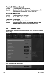
...Days) and Hour/ Minute/Second will become user-configurable with set values. 2.6 Monitor menu The Monitor menu displays the system temperature/power status, and allows you to display the following items: Anti Surge Support Enabled Version 2.00.1201. Advanced Mode Exit Main Ai ...the fan settings. F1: General Help F2: Previous Values F5: Optimized Defaults F10: Save ESC: Exit Version 2.00.1201. Power On By PME [Disabled] [Disabled] Disables PME wake from sleep states. [Enabled] Enables PME wake from sleep states. Copyright (C) 2010 American Megatrends, Inc. 2-18 ASUS E35M1-I
...Days) and Hour/ Minute/Second will become user-configurable with set values. 2.6 Monitor menu The Monitor menu displays the system temperature/power status, and allows you to display the following items: Anti Surge Support Enabled Version 2.00.1201. Advanced Mode Exit Main Ai ...the fan settings. F1: General Help F2: Previous Values F5: Optimized Defaults F10: Save ESC: Exit Version 2.00.1201. Power On By PME [Disabled] [Disabled] Disables PME wake from sleep states. [Enabled] Enables PME wake from sleep states. Copyright (C) 2010 American Megatrends, Inc. 2-18 ASUS E35M1-I

User Manual
Page 45
...information 2-21 Disables the full screen logo display feature. Copyright (C) 2010 American Megatrends, Inc. 2.7.1 [On] [Off] Bootup NumLock State [On] Sets the power-on device to [Off]. 2.7.2 [Enabled] [Disabled] Full Screen Logo [Enabled] Enables the full screen logo display feature. EFI BIOS Utility - Post Report [5... sec] This item appears only when the Full Screen Logo item is set to [Disabled] and allows you to use the ASUS MyLogo 2™ feature. F1: General Help F2: Previous Values F5: Optimized Defaults F10: Save ESC: Exit Version 2.00.1201. 2.7 ...
...information 2-21 Disables the full screen logo display feature. Copyright (C) 2010 American Megatrends, Inc. 2.7.1 [On] [Off] Bootup NumLock State [On] Sets the power-on device to [Off]. 2.7.2 [Enabled] [Disabled] Full Screen Logo [Enabled] Enables the full screen logo display feature. EFI BIOS Utility - Post Report [5... sec] This item appears only when the Full Screen Logo item is set to [Disabled] and allows you to use the ASUS MyLogo 2™ feature. F1: General Help F2: Previous Values F5: Optimized Defaults F10: Save ESC: Exit Version 2.00.1201. 2.7 ...


