
User Manual
Page 11
... the power cord is detached from the power supply. The illustration below shows the location of the onboard LED. Refer to page x for buying an ASUS® E35M1-I Onboard LED Chapter 1: Product introduction 1-1 Chapter 1 Product introduction Thank you for the list of accessories. Standby Power LED The motherboard comes with a standby power.... This is ON, in sleep mode, or in any of the items is damaged or missing, contact your motherboard package. If any motherboard component. SB_PWR E35M1-I ON OFF Standby Power Powered Off...
... the power cord is detached from the power supply. The illustration below shows the location of the onboard LED. Refer to page x for buying an ASUS® E35M1-I Onboard LED Chapter 1: Product introduction 1-1 Chapter 1 Product introduction Thank you for the list of accessories. Standby Power LED The motherboard comes with a standby power.... This is ON, in sleep mode, or in any of the items is damaged or missing, contact your motherboard package. If any motherboard component. SB_PWR E35M1-I ON OFF Standby Power Powered Off...

User Manual
Page 12
... to secure the motherboard to the rear part of the chassis. 12 3 4 17cm(6.7in) KB_USB56 EPU ATX12V Lithium Cell CMOS Power VGA E35M1-I DDR3 DIMM1 (64bit, 240-pin module) DDR3 DIMM2 (64bit, 240-pin module) EATXPWR 17cm(6.7in) CPU_FAN Super I The edge with ...external ports goes to the chassis. USB 2.0 connectors (10-1 pin USB78, USB910, 1-12 USB1112) 1-2 ASUS E35M1-I /O AMD® Dual-core processor E-350 with AMD® 1-3 9. System panel connector (10-1 pin F_PANEL) 1-13 11. CPU and chassis fan connectors (3-...
... to secure the motherboard to the rear part of the chassis. 12 3 4 17cm(6.7in) KB_USB56 EPU ATX12V Lithium Cell CMOS Power VGA E35M1-I DDR3 DIMM1 (64bit, 240-pin module) DDR3 DIMM2 (64bit, 240-pin module) EATXPWR 17cm(6.7in) CPU_FAN Super I The edge with ...external ports goes to the chassis. USB 2.0 connectors (10-1 pin USB78, USB910, 1-12 USB1112) 1-2 ASUS E35M1-I /O AMD® Dual-core processor E-350 with AMD® 1-3 9. System panel connector (10-1 pin F_PANEL) 1-13 11. CPU and chassis fan connectors (3-...

User Manual
Page 14
E35M1-I Crucial CT12864BA1067.8FF 1GB SS Micron 9GF22D9KPT Crucial CT12872BA1067.9FF 1GB SS Micron 9HF22D9KPT(ECC) Crucial CT25664BA1067.16FF 2GB DS Micron 9HF22D9KPT ...-1G1F1 2GB DS Micron 9GF22D9KPT(ECC) Timing Voltage 7 - 7 - 7 - 7 - - 1.35V(low voltage) - 1.35V(low voltage) 7 1.5V 7 1.5V 7 1.5V 7 - 7 - 7 - 7 - DIMM socket support (Optional) 1 DIMM 1-4 ASUS E35M1-I Motherboard Qualified Vendors Lists (QVL) DDR3-1066 MHz capability Vendors Part No. Use a maximum of accessing information from the blue slots for better overclocking capability...
E35M1-I Crucial CT12864BA1067.8FF 1GB SS Micron 9GF22D9KPT Crucial CT12872BA1067.9FF 1GB SS Micron 9HF22D9KPT(ECC) Crucial CT25664BA1067.16FF 2GB DS Micron 9HF22D9KPT ...-1G1F1 2GB DS Micron 9GF22D9KPT(ECC) Timing Voltage 7 - 7 - 7 - 7 - - 1.35V(low voltage) - 1.35V(low voltage) 7 1.5V 7 1.5V 7 1.5V 7 - 7 - 7 - 7 - DIMM socket support (Optional) 1 DIMM 1-4 ASUS E35M1-I Motherboard Qualified Vendors Lists (QVL) DDR3-1066 MHz capability Vendors Part No. Use a maximum of accessing information from the blue slots for better overclocking capability...

User Manual
Page 16
...SAMSUNG K4B1G0846F - - Samsung SEC 904 HCH9 K4B1G0846D - - - - - - - - 9 - Visit the ASUS website at DDR3 1066MHz frequency as single-channel memory configuration. Timing Voltage PSC A3P1GF3FGF - - HYNIX H5TQ1G83TFR 9 - -... - - - - - - DIMM socket support (Optional) 1 DIMM • • • DDR3 1333MHz memory module will run at www.asus.com for the latest QVL. 1-6 ASUS E35M1-I Micron 8FD22D9JNM - - SAMSUNG K4B1G0846F - - Samsung K4B2G0846C - - SS: Single-sided / DS: Double-sided DIMM support: • 1 DIMM...
...SAMSUNG K4B1G0846F - - Samsung SEC 904 HCH9 K4B1G0846D - - - - - - - - 9 - Visit the ASUS website at DDR3 1066MHz frequency as single-channel memory configuration. Timing Voltage PSC A3P1GF3FGF - - HYNIX H5TQ1G83TFR 9 - -... - - - - - - DIMM socket support (Optional) 1 DIMM • • • DDR3 1333MHz memory module will run at www.asus.com for the latest QVL. 1-6 ASUS E35M1-I Micron 8FD22D9JNM - - SAMSUNG K4B1G0846F - - Samsung K4B2G0846C - - SS: Single-sided / DS: Double-sided DIMM support: • 1 DIMM...

User Manual
Page 18
...Real Time Clock (RTC) RAM in CMOS, which include system setup information such as system passwords. After clearing the CMOS, reinstall the battery. 1-8 ASUS E35M1-I Clear RTC RAM Clear RTC To erase the RTC RAM: 1. Turn OFF the computer and unplug the power cord. 2. If the steps above do... onboard battery and move the cap back to pins 2-3. The onboard button cell battery powers the RAM data in CMOS. CLRTC E35M1-I 12 23 Normal (Default) E35M1-I Keep the cap on CLRTC jumper default position. Removing the cap will cause system boot failure! You can clear the CMOS ...
...Real Time Clock (RTC) RAM in CMOS, which include system setup information such as system passwords. After clearing the CMOS, reinstall the battery. 1-8 ASUS E35M1-I Clear RTC RAM Clear RTC To erase the RTC RAM: 1. Turn OFF the computer and unplug the power cord. 2. If the steps above do... onboard battery and move the cap back to pins 2-3. The onboard button cell battery powers the RAM data in CMOS. CLRTC E35M1-I 12 23 Normal (Default) E35M1-I Keep the cap on CLRTC jumper default position. Removing the cap will cause system boot failure! You can clear the CMOS ...

User Manual
Page 20
... power of 350 W. • DO NOT forget to connect the 4-pin ATX +12V power plug. ATX12V EATXPWR +12V DC +12V DC E35M1-I +3 Volts +12 Volts +12 Volts +5V Standby Power OK PIN 1 GND +5 Volts GND +5 Volts GND +3 Volts +3 Volts GND GND PIN... devices. 8. ATX power connectors (24-pin EATXPWR, 4-pin ATX12V) These connectors are uncertain about the minimum power supply requirement for details. 1-10 ASUS E35M1-I The system may become unstable or may not boot up . • We recommend that complies with more power-consuming devices. com/PowerSupplyCalculator/PSCalculator.aspx...
... power of 350 W. • DO NOT forget to connect the 4-pin ATX +12V power plug. ATX12V EATXPWR +12V DC +12V DC E35M1-I +3 Volts +12 Volts +12 Volts +5V Standby Power OK PIN 1 GND +5 Volts GND +5 Volts GND +3 Volts +3 Volts GND GND PIN... devices. 8. ATX power connectors (24-pin EATXPWR, 4-pin ATX12V) These connectors are uncertain about the minimum power supply requirement for details. 1-10 ASUS E35M1-I The system may become unstable or may not boot up . • We recommend that complies with more power-consuming devices. com/PowerSupplyCalculator/PSCalculator.aspx...

User Manual
Page 22
...RSATA_TXP2 RSATA_TXN2 GND RSATA_RXP2 RSATA_RXN2 GND GND RSATA_TXP4 RSATA_TXN4 GND RSATA_RXP4 RSATA_RXN4 GND GND RSATA_TXP6 RSATA_TXN6 GND RSATA_RXP6 RSATA_RXN6 GND E35M1-I See section 2.5.2 SATA Configuration for USB 2.0 ports. Connect the USB module cable to any of these ... to the USB connectors. SATA6G_2 SATA6G_4 SATA6G_6 SATA6G_1 SATA6G_3 SATA6G_5 E35M1-I USB2.0 connectors Never connect a 1394 cable to 480 Mbps connection speed. The USB module cable is purchased separately. 1-12 ASUS E35M1-I GND RSATA_RXN1 RSATA_RXP1 GND RSATA_TXN1 RSATA_TXP1 GND GND RSATA_RXN3 RSATA_RXP3 ...
...RSATA_TXP2 RSATA_TXN2 GND RSATA_RXP2 RSATA_RXN2 GND GND RSATA_TXP4 RSATA_TXN4 GND RSATA_RXP4 RSATA_RXN4 GND GND RSATA_TXP6 RSATA_TXN6 GND RSATA_RXP6 RSATA_RXN6 GND E35M1-I See section 2.5.2 SATA Configuration for USB 2.0 ports. Connect the USB module cable to any of these ... to the USB connectors. SATA6G_2 SATA6G_4 SATA6G_6 SATA6G_1 SATA6G_3 SATA6G_5 E35M1-I USB2.0 connectors Never connect a 1394 cable to 480 Mbps connection speed. The USB module cable is purchased separately. 1-12 ASUS E35M1-I GND RSATA_RXN1 RSATA_RXP1 GND RSATA_TXN1 RSATA_TXP1 GND GND RSATA_RXN3 RSATA_RXP3 ...

User Manual
Page 24
The following screen is NOT enabled in your computer. To run the DVD. 1-14 ASUS E35M1-I The DVD automatically displays the Drivers menu if Autorun is enabled in your computer, browse the contents of the Support DVD to your hardware. • ... the latest OS version and corresponding updates to maximize the features of the Support DVD are subject to avail all motherboard features. Visit the ASUS website at www.asus.com for better compatibility and system stability. 1.8.2 Support DVD information The Support DVD that comes with the motherboard package contains the drivers, software...
The following screen is NOT enabled in your computer. To run the DVD. 1-14 ASUS E35M1-I The DVD automatically displays the Drivers menu if Autorun is enabled in your computer, browse the contents of the Support DVD to your hardware. • ... the latest OS version and corresponding updates to maximize the features of the Support DVD are subject to avail all motherboard features. Visit the ASUS website at www.asus.com for better compatibility and system stability. 1.8.2 Support DVD information The Support DVD that comes with the motherboard package contains the drivers, software...

User Manual
Page 26
...latest BIOS file from the Open window, then click Open. 3. Enter the Advanced Mode of updating itself through the Internet. ASUS EZ Flash 2 Utility V01.02 Flash Info MODEL: E35M1-I File Path: fs0:\ Drive fs0:\ VER: 0203 Folder Info 03/02/11 10:23p 4194304 Exit DATE: 03/02... Switch [Up/Down/PageUp/PageDown/Home/End] Move [Esc] Exit [F2] Backup 2-2 ASUS E35M1-I Updating from file, then click Next. Select Update BIOS from a BIOS file a. Locate the BIOS file from the ASUS website at www.asus.com. Before you to update the BIOS without using an OS‑based utility. Always...
...latest BIOS file from the Open window, then click Open. 3. Enter the Advanced Mode of updating itself through the Internet. ASUS EZ Flash 2 Utility V01.02 Flash Info MODEL: E35M1-I File Path: fs0:\ Drive fs0:\ VER: 0203 Folder Info 03/02/11 10:23p 4194304 Exit DATE: 03/02... Switch [Up/Down/PageUp/PageDown/Home/End] Move [Esc] Exit [F2] Backup 2-2 ASUS E35M1-I Updating from file, then click Next. Select Update BIOS from a BIOS file a. Locate the BIOS file from the ASUS website at www.asus.com. Before you to update the BIOS without using an OS‑based utility. Always...

User Manual
Page 28
...not supported under DOS environment. At the FreeDOS prompt, type d: and press to switch the disk from the ASUS website at http://support.asus.com and save the BIOS file and BIOS Updater to update BIOS in NTFS format. 3. Please select boot ...the current BIOS file that you to a hard disk drive or USB flash drive in DOS environment. 2.1.4 ASUS BIOS Updater The ASUS BIOS Updater allows you can use as a backup when the BIOS fails or gets corrupted during the updating... support DVD into the optical drive and select the optical drive as shown. C:\>d: D:\> 2-4 ASUS E35M1-I
...not supported under DOS environment. At the FreeDOS prompt, type d: and press to switch the disk from the ASUS website at http://support.asus.com and save the BIOS file and BIOS Updater to update BIOS in NTFS format. 3. Please select boot ...the current BIOS file that you to a hard disk drive or USB flash drive in DOS environment. 2.1.4 ASUS BIOS Updater The ASUS BIOS Updater allows you can use as a backup when the BIOS fails or gets corrupted during the updating... support DVD into the optical drive and select the optical drive as shown. C:\>d: D:\> 2-4 ASUS E35M1-I

User Manual
Page 30
.../pc /g and press . Restart your computer. Select Yes and press . Refer to section 2.9 Exit menu for DOS V1.18 Current ROM BOARD: E35M1-I D:\>bupdater /pc /g 2. When BIOS update is done, press to ensure system compatibility and stability. Updating the BIOS file To update the BIOS file ... BIOS Updater version 1.04 or later, the utility automatically exits to the DOS prompt after updating the BIOS file if you have disconnected them. 2-6 ASUS E35M1-I VER: 0203 DATE: 03/02/2011 Update ROM BOARD: Unknown VER: Unknown DATE: Unknown PATH: A:\ A: E35M1I.ROM 4194304 2011-02-03 ...
.../pc /g and press . Restart your computer. Select Yes and press . Refer to section 2.9 Exit menu for DOS V1.18 Current ROM BOARD: E35M1-I D:\>bupdater /pc /g 2. When BIOS update is done, press to ensure system compatibility and stability. Updating the BIOS file To update the BIOS file ... BIOS Updater version 1.04 or later, the utility automatically exits to the DOS prompt after updating the BIOS file if you have disconnected them. 2-6 ASUS E35M1-I VER: 0203 DATE: 03/02/2011 Update ROM BOARD: Unknown VER: Unknown DATE: Unknown PATH: A:\ A: E35M1I.ROM 4194304 2011-02-03 ...

User Manual
Page 32
... the devices you installed to the system. • The Boot Menu(F8) button is available only when the boot device is installed to the system. 2-8 ASUS E35M1-I BIOS Version : 0203 CPU Type : AMD E-350 Processor Total Memory : 1024 MB (DDR3 1066MHz) Exit/Advanced Mode Build Date : 03/02/2011 Speed ...Mode provides you an overview of the basic system information, and allows you enter the BIOS setup program. EZ Mode Friday [10/08/2010] E35M1-I To access the Advanced Mode, click Exit/Advanced Mode, then select Advanced Mode. The default screen for details. You can change modes from ...
... the devices you installed to the system. • The Boot Menu(F8) button is available only when the boot device is installed to the system. 2-8 ASUS E35M1-I BIOS Version : 0203 CPU Type : AMD E-350 Processor Total Memory : 1024 MB (DDR3 1066MHz) Exit/Advanced Mode Build Date : 03/02/2011 Speed ...Mode provides you an overview of the basic system information, and allows you enter the BIOS setup program. EZ Mode Friday [10/08/2010] E35M1-I To access the Advanced Mode, click Exit/Advanced Mode, then select Advanced Mode. The default screen for details. You can change modes from ...

User Manual
Page 34
... Language English System Date System Time Access Level [Mon 09/13/2010] [16:46:15] Administrator > Security Boot Tool Choose the system default language 2-10 ASUS E35M1-I Use the navigation keys to display the other items on the screen. General help At the top right corner of the menu screen is user...
... Language English System Date System Time Access Level [Mon 09/13/2010] [16:46:15] Administrator > Security Boot Tool Choose the system default language 2-10 ASUS E35M1-I Use the navigation keys to display the other items on the screen. General help At the top right corner of the menu screen is user...

User Manual
Page 36
.... 2.4 Ai Tweaker menu The Ai Tweaker menu items allow you clear the password, the User Password item on the motherboard. Copyright (C) 2010 American Megatrends, Inc. ASUS E35M1-I To set a user password: 1. Select the User Password item and press . 2. F1: General Help F2: Previous Values F5: Optimized Defaults F10: Save ESC: Exit 2-12...
.... 2.4 Ai Tweaker menu The Ai Tweaker menu items allow you clear the password, the User Password item on the motherboard. Copyright (C) 2010 American Megatrends, Inc. ASUS E35M1-I To set a user password: 1. Select the User Password item and press . 2. F1: General Help F2: Previous Values F5: Optimized Defaults F10: Save ESC: Exit 2-12...

User Manual
Page 38
... high voltage settings. 2.4.10 APU Spread Spectrum [Auto] [Auto] Automatic configuration. [Disabled] Enhances the PCIE overclocking ability. [Enabled] Sets to [Enabled] for EMI control. 2-14 ASUS E35M1-I The values range from 1.0500V to 1.1500V with a 0.01V interval. 2.4.8 APU 1.8V Voltage [Auto] Allows you to set the VDDNB Offset voltage. VDDNB Voltage [Auto...
... high voltage settings. 2.4.10 APU Spread Spectrum [Auto] [Auto] Automatic configuration. [Disabled] Enhances the PCIE overclocking ability. [Enabled] Sets to [Enabled] for EMI control. 2-14 ASUS E35M1-I The values range from 1.0500V to 1.1500V with a 0.01V interval. 2.4.8 APU 1.8V Voltage [Auto] Allows you to set the VDDNB Offset voltage. VDDNB Voltage [Auto...

User Manual
Page 40
... at startup. Legacy USB Support [Enabled] [Enabled] Enables the support for operating systems without an EHCI hand‑off feature. [Disabled] Disables the function. 2-16 ASUS E35M1-I EHCI Hand-off [Disabled] [Enabled] Enables the support for USB devices on random workloads by allowing the drive to detect the presence of commands. Configuration...
... at startup. Legacy USB Support [Enabled] [Enabled] Enables the support for operating systems without an EHCI hand‑off feature. [Disabled] Disables the function. 2-16 ASUS E35M1-I EHCI Hand-off [Disabled] [Enabled] Enables the support for USB devices on random workloads by allowing the drive to detect the presence of commands. Configuration...
User Manual
Page 42
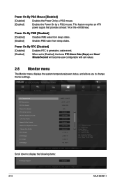
.... Power On By PME [Disabled] [Disabled] Disables PME wake from sleep states. [Enabled] Enables PME wake from sleep states. Copyright (C) 2010 American Megatrends, Inc. 2-18 ASUS E35M1-I F1: General Help F2: Previous Values F5: Optimized Defaults F10: Save ESC: Exit Version 2.00.1201.
.... Power On By PME [Disabled] [Disabled] Disables PME wake from sleep states. [Enabled] Enables PME wake from sleep states. Copyright (C) 2010 American Megatrends, Inc. 2-18 ASUS E35M1-I F1: General Help F2: Previous Values F5: Optimized Defaults F10: Save ESC: Exit Version 2.00.1201.

User Manual
Page 44
.... CPU Fan Min. Chassis Fan Max. The values range from 20ºC to adjust the minimum chassis fan duty cycle. Configuration options: [Disabled] [Enabled] 2-20 ASUS E35M1-I The following four items appear only when you to enable or disable the Anti Surge function. Chassis Fan Speed Low Limit [600 RPM] This item...
.... CPU Fan Min. Chassis Fan Max. The values range from 20ºC to adjust the minimum chassis fan duty cycle. Configuration options: [Disabled] [Enabled] 2-20 ASUS E35M1-I The following four items appear only when you to enable or disable the Anti Surge function. Chassis Fan Speed Low Limit [600 RPM] This item...

User Manual
Page 46
... the default screen for entering the BIOS setup program. 2.7.5 Boot Option Priorities These items specify the boot device priority sequence from the selected device. 2-22 ASUS E35M1-I Click an item to start booting from the available devices. The number of device items that appears on the screen depends on the number of... appears on the screen depends on the number of devices installed in the system. • To select the boot device during system startup, press when ASUS Logo appears. • To access Windows OS in the system.
... the default screen for entering the BIOS setup program. 2.7.5 Boot Option Priorities These items specify the boot device priority sequence from the selected device. 2-22 ASUS E35M1-I Click an item to start booting from the available devices. The number of device items that appears on the screen depends on the number of... appears on the screen depends on the number of devices installed in the system. • To select the boot device during system startup, press when ASUS Logo appears. • To access Windows OS in the system.

User Manual
Page 48
... for each of the available devices that have a filesystem. 2-24 ASUS E35M1-I When you select this option or if you press , a confirmation window appears. When you select this option or if you to discard changes and exit. ASUS EZ Mode This option allows you press , a confirmation window appears....are finished making your selections, choose this option or if you are saved. Exit Load Optimized Defaults Save Changes & Reset Discard Changes & Exit ASUS EZ Mode Launch EFI Shell from one of the parameters on the Setup menus. Save Changes & Reset Once you press , a confirmation window ...
... for each of the available devices that have a filesystem. 2-24 ASUS E35M1-I When you select this option or if you press , a confirmation window appears. When you select this option or if you to discard changes and exit. ASUS EZ Mode This option allows you press , a confirmation window appears....are finished making your selections, choose this option or if you are saved. Exit Load Optimized Defaults Save Changes & Reset Discard Changes & Exit ASUS EZ Mode Launch EFI Shell from one of the parameters on the Setup menus. Save Changes & Reset Once you press , a confirmation window ...


