

User Guide
Page 5
... 5.6 Boot menu 5-25 5.7 Exit menu 5-27 Appendix A.1 Subsystem A-2 A.1.1 Front and rear panel features A-2 A.1.2 Removing the top cover A-3 A.1.3 Installing a hard disk drive A-3 A.1.4 Connecting the Subsystem to DiGiMatrix A-4 A.2 DiGiMatrix remote controller A-5 A.2.1 Specifications A-5 A.2.2 Remote control layout A-5 A.2.3 Remote control functions in Audio DJ A-6 A.2.4 Remote control functions in Home Theater .......... A-7 A.3 Optical drive technical specifications A-9 A.4 Wireless LAN adapter channels A-10 ASUS DiGiMatrix v
... 5.6 Boot menu 5-25 5.7 Exit menu 5-27 Appendix A.1 Subsystem A-2 A.1.1 Front and rear panel features A-2 A.1.2 Removing the top cover A-3 A.1.3 Installing a hard disk drive A-3 A.1.4 Connecting the Subsystem to DiGiMatrix A-4 A.2 DiGiMatrix remote controller A-5 A.2.1 Specifications A-5 A.2.2 Remote control layout A-5 A.2.3 Remote control functions in Audio DJ A-6 A.2.4 Remote control functions in Home Theater .......... A-7 A.3 Optical drive technical specifications A-9 A.4 Wireless LAN adapter channels A-10 ASUS DiGiMatrix v
User Guide
Page 8
... chapters: 1. Chapter 4: Motherboard Information This chapter gives information about the ASUS DiGiMatrix. Chapter 1: System Introduction This chapter gives a general description of personal ...DiGiMatrix Subsystem, remote controller, optical drive technical specifications, and IEEE 802.11b channels for experienced users and integrators with the system. Chapter 2: Basic Installation This chapter provides step-by-step instructions on the front and rear panel, and internal components. 2. Chapter 5: BIOS information This chapter tells how to install components in the ASUS DiGiMatrix...
... chapters: 1. Chapter 4: Motherboard Information This chapter gives information about the ASUS DiGiMatrix. Chapter 1: System Introduction This chapter gives a general description of personal ...DiGiMatrix Subsystem, remote controller, optical drive technical specifications, and IEEE 802.11b channels for experienced users and integrators with the system. Chapter 2: Basic Installation This chapter provides step-by-step instructions on the front and rear panel, and internal components. 2. Chapter 5: BIOS information This chapter tells how to install components in the ASUS DiGiMatrix...
User Guide
Page 16
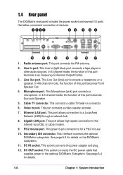
... and plug. 12. This Line Out (lime) port connects a headphone or a speaker. This connects a cable TV twist-on the DiGiMatrix subsystem. 11. This port allows high speed connection to a Local Area Network (LAN) through a network hub. 8. DC OUT socket. This... Microphone (pink) port connects a microphone. Line In port. Gigabit LAN port. Secondary IDE connector. This interface connects the optional DiGiMatrix subsystem. Radio antenna port. Microphone port. This socket connects the DC power cable that allow convenient connection of this port becomes Front Speaker...
... and plug. 12. This Line Out (lime) port connects a headphone or a speaker. This connects a cable TV twist-on the DiGiMatrix subsystem. 11. This port allows high speed connection to a Local Area Network (LAN) through a network hub. 8. DC OUT socket. This... Microphone (pink) port connects a microphone. Line In port. Gigabit LAN port. Secondary IDE connector. This interface connects the optional DiGiMatrix subsystem. Radio antenna port. Microphone port. This socket connects the DC power cable that allow convenient connection of this port becomes Front Speaker...
User Guide
Page 32
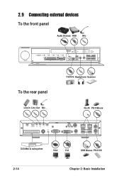
2.9 Connecting external devices To the front panel Audio Devices HDD Mic - VOLUME + To the rear panel Line In Line Out Mic Camera Headphone Scanner RJ-45 PS/2 Mouse DiGiMatrix subsystem VGA DVI USB Mouse PS/2 KB 2-14 Chapter 2: Basic Installation
2.9 Connecting external devices To the front panel Audio Devices HDD Mic - VOLUME + To the rear panel Line In Line Out Mic Camera Headphone Scanner RJ-45 PS/2 Mouse DiGiMatrix subsystem VGA DVI USB Mouse PS/2 KB 2-14 Chapter 2: Basic Installation
User Guide
Page 107
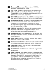
... monitors CPU and chassis fan speeds and other system conditions. This SiS651 controller integrates a high performance host interface for storage cards. 9 Card reader firmware. ASUS DiGiMatrix 4-3 This connects the DiGiMatrix subsystem for the card reader. 10 Flash EEPROM. This is an AC '97 compliant audio CODEC that allows 4.3GB/s and 3.2GB/s data transfer rates...
... monitors CPU and chassis fan speeds and other system conditions. This SiS651 controller integrates a high performance host interface for storage cards. 9 Card reader firmware. ASUS DiGiMatrix 4-3 This connects the DiGiMatrix subsystem for the card reader. 10 Flash EEPROM. This is an AC '97 compliant audio CODEC that allows 4.3GB/s and 3.2GB/s data transfer rates...
User Guide
Page 114
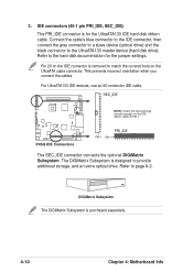
3. Refer to the UltraATA133 master device (hard disk drive). The DiGiMatrix Subsystem is purchased separately. 4-10 Chapter 4: Motherboard Info DiGiMatrix Subsystem The DiGiMatrix Subsystem is designed to provide additional storage, and an extra optical drive. Refer to PIN 1.... the red markings (usually zigzag) on the UltraATA cable connector. PRI_IDE PIN 1 PIN 1 The SEC_IDE connector connects the optional DiGiMatrix Subsystem. This prevents incorrect orientation when you connect the cables. For UltraATA133 IDE devices, use an 80-conductor IDE cable. IDE connectors...
3. Refer to the UltraATA133 master device (hard disk drive). The DiGiMatrix Subsystem is purchased separately. 4-10 Chapter 4: Motherboard Info DiGiMatrix Subsystem The DiGiMatrix Subsystem is designed to provide additional storage, and an extra optical drive. Refer to PIN 1.... the red markings (usually zigzag) on the UltraATA cable connector. PRI_IDE PIN 1 PIN 1 The SEC_IDE connector connects the optional DiGiMatrix Subsystem. This prevents incorrect orientation when you connect the cables. For UltraATA133 IDE devices, use an 80-conductor IDE cable. IDE connectors...
User Guide
Page 147
ASUS DiGiMatrix Appendix Appendix The Appendix provides information on the DiGiMatrix Subsystem, remote controller, optical drive technical specifications, and IEEE 802.11b channels for the wireless LAN adapter.
ASUS DiGiMatrix Appendix Appendix The Appendix provides information on the DiGiMatrix Subsystem, remote controller, optical drive technical specifications, and IEEE 802.11b channels for the wireless LAN adapter.
User Guide
Page 148
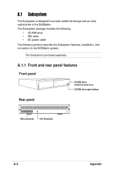
The Subsystem is designed to provide additional storage and an extra optical drive to the DiGiMatrix system. A.1 Subsystem The Subsystem is purchased separately. The Subsystem package includes the following. • CD-RW drive • IDE cable • DC power cable The following sections describe the Subsystem features, installation, and connection to the DiGiMatrix. A.1.1 Front and rear panel features Front panel CD-RW drive (inside the panel door) CD-RW drive eject button Rear panel IDE connector DC IN socket A-2 Appendix
The Subsystem is designed to provide additional storage and an extra optical drive to the DiGiMatrix system. A.1 Subsystem The Subsystem is purchased separately. The Subsystem package includes the following. • CD-RW drive • IDE cable • DC power cable The following sections describe the Subsystem features, installation, and connection to the DiGiMatrix. A.1.1 Front and rear panel features Front panel CD-RW drive (inside the panel door) CD-RW drive eject button Rear panel IDE connector DC IN socket A-2 Appendix
User Guide
Page 149
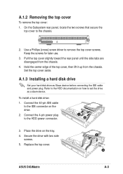
... aside. To install a hard disk drive: 1. Connect the 40-pin IDE cable to remove the top cover screws. Replace the top cover. 3 4 ASUS DiGiMatrix A-3 Use a Phillips (cross) screw driver to the IDE connector on the tray. 4. Pull the top cover slightly toward the rear panel until the side...the chassis. A.1.3 Installing a hard disk drive Set your hard disk drive as a slave device. Place the drive on the drive. 2. On the Subsystem rear panel, locate the two screws that secure the top cover to the chassis. 2. Secure the drive with two side screws. 5. Hold the center...
... aside. To install a hard disk drive: 1. Connect the 40-pin IDE cable to remove the top cover screws. Replace the top cover. 3 4 ASUS DiGiMatrix A-3 Use a Phillips (cross) screw driver to the IDE connector on the tray. 4. Pull the top cover slightly toward the rear panel until the side...the chassis. A.1.3 Installing a hard disk drive Set your hard disk drive as a slave device. Place the drive on the drive. 2. On the Subsystem rear panel, locate the two screws that secure the top cover to the chassis. 2. Secure the drive with two side screws. 5. Hold the center...
User Guide
Page 150
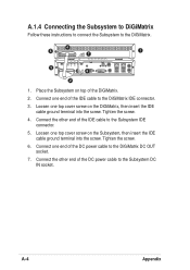
... one top cover screw on top of the IDE cable to the Subsystem IDE connector. 5. A-4 Appendix Tighten the screw. 4. Tighten the screw. 6. A.1.4 Connecting the Subsystem to DiGiMatrix Follow these instructions to connect the Subsystem to the DiGiMatrix DC OUT socket. 7. Place the Subsystem on the DiGiMatrix, then insert the IDE cable ground terminal into the screw. Connect...
... one top cover screw on top of the IDE cable to the Subsystem IDE connector. 5. A-4 Appendix Tighten the screw. 4. Tighten the screw. 6. A.1.4 Connecting the Subsystem to DiGiMatrix Follow these instructions to connect the Subsystem to the DiGiMatrix DC OUT socket. 7. Place the Subsystem on the DiGiMatrix, then insert the IDE cable ground terminal into the screw. Connect...