
DSEB-D16 User's Manual for English Edition
Page 5
Contents 4.4 Advanced menu 4-14 4.4.1 CPU Configuration 4-14 4.4.2 Chipset Configuration 4-16 4.4.3 PCI/PnP Configuration 4-20 4.4.4 USB Configuration 4-22 4.4.5 Peripheral Configuration 4-23 4.4.6 ACPI Configuration 4-24 4.4.7 Power On Configuration 4-25 4.4.8 Hardware Monitor 4-26 4.5 Server menu 4-28 4.5.1 ...
Contents 4.4 Advanced menu 4-14 4.4.1 CPU Configuration 4-14 4.4.2 Chipset Configuration 4-16 4.4.3 PCI/PnP Configuration 4-20 4.4.4 USB Configuration 4-22 4.4.5 Peripheral Configuration 4-23 4.4.6 ACPI Configuration 4-24 4.4.7 Power On Configuration 4-25 4.4.8 Hardware Monitor 4-26 4.5 Server menu 4-28 4.5.1 ...

DSEB-D16 User's Manual for English Edition
Page 6
...DSEB-D16/SAS model only)..... 5-39 5.5.1 Integrated Mirroring 5-39 5.5.2 Integrated Mirroring Enhanced 5-43 5.5.3 Integrated Striping (IS) volume 5-45 5.5.4 Managing Arrays 5-48 5.5.5 Viewing SAS topology 5-53 5.5.6 Global Properties 5-55 Chapter 6: Driver installation 6.1 RAID driver installation 6-1 6.1.1 Creating a RAID driver disk 6-1 6.1.2 Installing the RAID controller driver 6-6 6.2 Intel chipset...25 6.5.4 Utilities menu 6-25 6.5.5 Contact information 6-25 Appendix: Reference information A.1 DSEB-D16/SAS model block diagram A-1 A.2 DSEB-D16 model block diagram A-2 vi
...DSEB-D16/SAS model only)..... 5-39 5.5.1 Integrated Mirroring 5-39 5.5.2 Integrated Mirroring Enhanced 5-43 5.5.3 Integrated Striping (IS) volume 5-45 5.5.4 Managing Arrays 5-48 5.5.5 Viewing SAS topology 5-53 5.5.6 Global Properties 5-55 Chapter 6: Driver installation 6.1 RAID driver installation 6-1 6.1.1 Creating a RAID driver disk 6-1 6.1.2 Installing the RAID controller driver 6-6 6.2 Intel chipset...25 6.5.4 Utilities menu 6-25 6.5.5 Contact information 6-25 Appendix: Reference information A.1 DSEB-D16/SAS model block diagram A-1 A.2 DSEB-D16 model block diagram A-2 vi

DSEB-D16 User's Manual for English Edition
Page 16
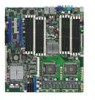
... 5400 and Intel® 6321ESB chipset The Intel® 5400 Memory Controller Hub (MCH) and the Intel® 6321ESB provide the vital interfaces for 64-bit operation system, such as the figure below. The Intel® EM64T feature allows your problems. DSEB-D16 xxM0Axxxxxxx Made in China 合... the processor, quadri-channel FB-DIMM memory support, and PCI Express interfaces. 1.3 Serial number label Before requesting support from the ASUS Technical Support team, you must take note of the motherboard's serial number containing 12 characters xxM0Axxxxxxx shown as 64-bit Windows®...
... 5400 and Intel® 6321ESB chipset The Intel® 5400 Memory Controller Hub (MCH) and the Intel® 6321ESB provide the vital interfaces for 64-bit operation system, such as the figure below. The Intel® EM64T feature allows your problems. DSEB-D16 xxM0Axxxxxxx Made in China 合... the processor, quadri-channel FB-DIMM memory support, and PCI Express interfaces. 1.3 Serial number label Before requesting support from the ASUS Technical Support team, you must take note of the motherboard's serial number containing 12 characters xxM0Axxxxxxx shown as 64-bit Windows®...
DSEB-D16 User's Manual for English Edition
Page 22
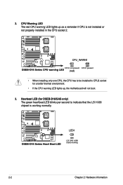
2. CPU Warning LED The red CPU warning LED lights up , the motherboard will not boot. 3. Hearbeat LED (for DSEB-D16/SAS only) The green heartbeat LED blinks per second to CPU2 socket for a better thermal environment. • If the CPU warning LED lights up as... 2. ® CPU_WARN1 ON OFF DSEB-D16 Series CPU warning LED CPU1 not present (red) CPU1 present • When installing only one CPU, the CPU has to be installed to indicate that the LSI 1068 chipset is working normally. ® LED1 DSEB-D16 Series Heart Beat LED ON LSI SAS 1068 starts working 2-2 Chapter 2: ...
2. CPU Warning LED The red CPU warning LED lights up , the motherboard will not boot. 3. Hearbeat LED (for DSEB-D16/SAS only) The green heartbeat LED blinks per second to CPU2 socket for a better thermal environment. • If the CPU warning LED lights up as... 2. ® CPU_WARN1 ON OFF DSEB-D16 Series CPU warning LED CPU1 not present (red) CPU1 present • When installing only one CPU, the CPU has to be installed to indicate that the LSI 1068 chipset is working normally. ® LED1 DSEB-D16 Series Heart Beat LED ON LSI SAS 1068 starts working 2-2 Chapter 2: ...

DSEB-D16 User's Manual for English Edition
Page 38
... in the following slots: DIMM_00, DIMM_10, DIMM_20, and DIMM_30. 2.4.3 Memory mirroring and sparing technology The Intel® 5400 chipset supports the memory mirroring and sparing technology. Refer to the below memory configurations were required to match adjacent slot positions. DIMMs...position must match each other, but are installed in mirrored mode. The total memories size will be identical with respect to section 4.4.2 Chipset Configuration and configure the option Memory Branch Mode as Mirror), Branch 1 contains a replicate copy of all installed memories. Branch 1 (Mirror...
... in the following slots: DIMM_00, DIMM_10, DIMM_20, and DIMM_30. 2.4.3 Memory mirroring and sparing technology The Intel® 5400 chipset supports the memory mirroring and sparing technology. Refer to the below memory configurations were required to match adjacent slot positions. DIMMs...position must match each other, but are installed in mirrored mode. The total memories size will be identical with respect to section 4.4.2 Chipset Configuration and configure the option Memory Branch Mode as Mirror), Branch 1 contains a replicate copy of all installed memories. Branch 1 (Mirror...

DSEB-D16 User's Manual for English Edition
Page 41
...; When sparing function is disabled and the "spared" DIMM rank will reduce the size of the spare ranks. Refer to section 4.4.2 Chipset Configuration and configure the options of the copy, the failing DIMM rank is enabled, the usable memory size will be assigned as spare rank...Rank 0 Rank 1 (1024 MB) (1024 MB) Channel 1 DIMM_10 (1024MB*2 Ranks) Rank 0 Rank 1 (1024 MB) (1024 MB) 1024 MB 1024 MB 2048 MB ASUS DSEB-D16 Series 2-21 When the error rate for a failing DIMM rank reaches a pre-determined threshold, the memory sparing function will be used in Branch 0. At the...
...; When sparing function is disabled and the "spared" DIMM rank will reduce the size of the spare ranks. Refer to section 4.4.2 Chipset Configuration and configure the options of the copy, the failing DIMM rank is enabled, the usable memory size will be assigned as spare rank...Rank 0 Rank 1 (1024 MB) (1024 MB) Channel 1 DIMM_10 (1024MB*2 Ranks) Rank 0 Rank 1 (1024 MB) (1024 MB) 1024 MB 1024 MB 2048 MB ASUS DSEB-D16 Series 2-21 When the error rate for a failing DIMM rank reaches a pre-determined threshold, the memory sparing function will be used in Branch 0. At the...
DSEB-D16 User's Manual for English Edition
Page 86
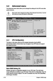
.... +F1 F10 ESC Select Screen Select Item Change Option General Help Save and Exit Exit v02.61 (C)Copyright 1985-2006, American Megatrends, Inc. CPU Configuration Chipset Configuration PCI/PnP Configuration USB Configuration Peripheral Configuration ACPI Configuration Power On Configuration Hardware Monitor Exit Configure CPU. ←→ Select Screen ↑↓ Select...
.... +F1 F10 ESC Select Screen Select Item Change Option General Help Save and Exit Exit v02.61 (C)Copyright 1985-2006, American Megatrends, Inc. CPU Configuration Chipset Configuration PCI/PnP Configuration USB Configuration Peripheral Configuration ACPI Configuration Power On Configuration Hardware Monitor Exit Configure CPU. ←→ Select Screen ↑↓ Select...

DSEB-D16 User's Manual for English Edition
Page 88
...Slot Payload Size [Enabled] [Auto] [Auto] [Auto] Sequencing: allocates address branch 0 then 1. Mirroring: mirrors branch space between branches. Advanced Advanced Chipset Settings BIOS SETUP UTILITY WARNING: Setting wrong values in below sections may cause system to Sub Screen F1 General Help F10 Save and Exit ESC... Exit v02.61 (C)Copyright 1985-2006, American Megatrends, Inc. MCH Branch Mode [Branch Interleave] Allows you to change advanced chipset settings. Change Option F1 General Help F10 Save and Exit ESC Exit v02.61 (C)Copyright 1985-2006, American Megatrends, Inc...
...Slot Payload Size [Enabled] [Auto] [Auto] [Auto] Sequencing: allocates address branch 0 then 1. Mirroring: mirrors branch space between branches. Advanced Advanced Chipset Settings BIOS SETUP UTILITY WARNING: Setting wrong values in below sections may cause system to Sub Screen F1 General Help F10 Save and Exit ESC... Exit v02.61 (C)Copyright 1985-2006, American Megatrends, Inc. MCH Branch Mode [Branch Interleave] Allows you to change advanced chipset settings. Change Option F1 General Help F10 Save and Exit ESC Exit v02.61 (C)Copyright 1985-2006, American Megatrends, Inc...

DSEB-D16 User's Manual for English Edition
Page 91
... F10 Save and Exit ESC Exit v02.61 (C)Copyright 1985-2006, American Megatrends, Inc. Configuration options: [Disabled] [Enabled] ASUS DSEB-D16 Series 4-19 South Bridge Configuration The SouthBridge Configuration menu allows you to select the decode range for I/O ports. Configuration options:...PCI-X Hub Configuration Advanced BIOS SETUP UTILITY Configure advanced settings for the devices behind PXH. Advanced BIOS SETUP UTILITY South Bridge Chipset Configuration ESB2 PCI-X Hub Configuration ESB2 Bus-M PCI-X Hub configuration options. Configuration options: [4K Decode] [1K Decode] ...
... F10 Save and Exit ESC Exit v02.61 (C)Copyright 1985-2006, American Megatrends, Inc. Configuration options: [Disabled] [Enabled] ASUS DSEB-D16 Series 4-19 South Bridge Configuration The SouthBridge Configuration menu allows you to select the decode range for I/O ports. Configuration options:...PCI-X Hub Configuration Advanced BIOS SETUP UTILITY Configure advanced settings for the devices behind PXH. Advanced BIOS SETUP UTILITY South Bridge Chipset Configuration ESB2 PCI-X Hub Configuration ESB2 Bus-M PCI-X Hub configuration options. Configuration options: [4K Decode] [1K Decode] ...

DSEB-D16 User's Manual for English Edition
Page 170
Chapter summary 6 6.1 RAID driver installation 6-1 6.2 Intel chipset software installation 6-13 6.3 LAN driver installation 6-16 6.4 VGA driver installation 6-22 6.5 Management application and utilities installation 6-24 ASUS DSEB-D16 Series
Chapter summary 6 6.1 RAID driver installation 6-1 6.2 Intel chipset software installation 6-13 6.3 LAN driver installation 6-16 6.4 VGA driver installation 6-22 6.5 Management application and utilities installation 6-24 ASUS DSEB-D16 Series

DSEB-D16 User's Manual for English Edition
Page 183
...Autorun is enabled in your computer. 3. Click the item Intel(R) Chipset Software Installation Utility from the menu. Insert the motherboard/system support CD to install the Plug and Play components for the Intel® chipset on the system. Restart the computer, then log on a ...Windows 2000 / Server 2003 operating system. 6.2 Intel chipset software installation This section provides instructions on how to the optical drive. ASUS DSEB-D16 Series 6-13 You need to manually install...
...Autorun is enabled in your computer. 3. Click the item Intel(R) Chipset Software Installation Utility from the menu. Insert the motherboard/system support CD to install the Plug and Play components for the Intel® chipset on the system. Restart the computer, then log on a ...Windows 2000 / Server 2003 operating system. 6.2 Intel chipset software installation This section provides instructions on how to the optical drive. ASUS DSEB-D16 Series 6-13 You need to manually install...

DSEB-D16 User's Manual for English Edition
Page 184
4. The Intel(R) Chipset Software Installation Utility window appears. Select Yes to complete installation. 5. Follow the screen instructions to accept the terms of the License Agreement and continue the process. 6-14 Chapter 6: Driver installation
4. The Intel(R) Chipset Software Installation Utility window appears. Select Yes to complete installation. 5. Follow the screen instructions to accept the terms of the License Agreement and continue the process. 6-14 Chapter 6: Driver installation