

CUR-DLS User Manual
Page 1
® CUR-DLS Dual Socket370 Motherboard USER'S MANUAL
® CUR-DLS Dual Socket370 Motherboard USER'S MANUAL

CUR-DLS User Manual
Page 4
FEATURES 8 2.1 The ASUS CUR-DLS 8 2.1.1 Specifications 8 2.1.2 Specifications-Optional Components 9 2.1.3 Performance 10 2.1.4 Intelligence 11 2.2 CUR-DLS Motherboard Components 12 2.2.1 Component Locations 13 3. HARDWARE SETUP 14 3.1 CUR-DLS Motherboard Layout 14 3.2 Layout Contents 15 3.3 Hardware Setup Procedure 16 3.4 Motherboard Settings 16 3.5 System Memory (DIMM 17 3.5.1 SDRAM Configurations 17 3.5.2 DIMM Installation 18 3.6 Central Processing Unit (CPU 19 3.7.1 Expansion Card Installation Procedure 20 3.7 Expansion Cards...
FEATURES 8 2.1 The ASUS CUR-DLS 8 2.1.1 Specifications 8 2.1.2 Specifications-Optional Components 9 2.1.3 Performance 10 2.1.4 Intelligence 11 2.2 CUR-DLS Motherboard Components 12 2.2.1 Component Locations 13 3. HARDWARE SETUP 14 3.1 CUR-DLS Motherboard Layout 14 3.2 Layout Contents 15 3.3 Hardware Setup Procedure 16 3.4 Motherboard Settings 16 3.5 System Memory (DIMM 17 3.5.1 SDRAM Configurations 17 3.5.2 DIMM Installation 18 3.6 Central Processing Unit (CPU 19 3.7.1 Expansion Card Installation Procedure 20 3.7 Expansion Cards...
CUR-DLS User Manual
Page 7
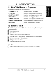
... Intructions on setting up the included software Reference material for a 3.5" floppy disk drive (1) Support drivers and utilities (1) This Motherboard User's Manual Optional Items (1) Socket 370 CPU Terminator (required when installing only one CPU) ASUS CUR-DLS User's Manual 7 INTRODUCTION 2. SOFTWARE SETUP 6. 1.INTRODUCTION Manual/Checklist 1. BIOS SETUP 5. FEATURES 3. APPENDIX Manual information and checklist Production information...
... Intructions on setting up the included software Reference material for a 3.5" floppy disk drive (1) Support drivers and utilities (1) This Motherboard User's Manual Optional Items (1) Socket 370 CPU Terminator (required when installing only one CPU) ASUS CUR-DLS User's Manual 7 INTRODUCTION 2. SOFTWARE SETUP 6. 1.INTRODUCTION Manual/Checklist 1. BIOS SETUP 5. FEATURES 3. APPENDIX Manual information and checklist Production information...

CUR-DLS User Manual
Page 8
..., and Netware when dual processors of Ownership (TCO). • 4GB PC133 Memory Support: Equipped with ECC, dual peer to 30 SCSI devices. FEATURES 2.1 The ASUS CUR-DLS The ASUS CUR-DLS motherboard is carefully designed for the demanding corporate user who wants advanced features processed by the fastest processors for Management, remote wake-up to peer PCI...
..., and Netware when dual processors of Ownership (TCO). • 4GB PC133 Memory Support: Equipped with ECC, dual peer to 30 SCSI devices. FEATURES 2.1 The ASUS CUR-DLS The ASUS CUR-DLS motherboard is carefully designed for the demanding corporate user who wants advanced features processed by the fastest processors for Management, remote wake-up to peer PCI...
CUR-DLS User Manual
Page 9
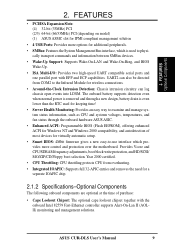
... design, battery drain is used to -use interface which provides more control and protection over the motherboard. 2. FEATURES • PCI/ISA Expansion Slots: (4) 32-bit (33MHz) PCI (2/3) 64-bit (66/33MHz) PCI (depending on model) (1) ASUS ASMC slot for IPMI compliant management solution • 4 USB Ports: Provides more options for additional ... compatible serial ports and one parallel port with the onboard Intel 82559 Fast-Ethernet controller supports Alert-On-Lan II (AOLII) monitoring and management solutions. ASUS CUR-DLS User's Manual 9 FEATURES Optional Components 2.
... design, battery drain is used to -use interface which provides more control and protection over the motherboard. 2. FEATURES • PCI/ISA Expansion Slots: (4) 32-bit (33MHz) PCI (2/3) 64-bit (66/33MHz) PCI (depending on model) (1) ASUS ASMC slot for IPMI compliant management solution • 4 USB Ports: Provides more options for additional ... compatible serial ports and one parallel port with the onboard Intel 82559 Fast-Ethernet controller supports Alert-On-Lan II (AOLII) monitoring and management solutions. ASUS CUR-DLS User's Manual 9 FEATURES Optional Components 2.
CUR-DLS User Manual
Page 10
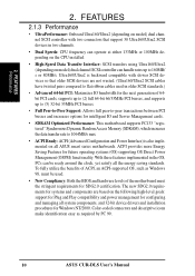
... required by PC 99. 10 ASUS CUR-DLS User's Manual 2. FEATURES Performance 2. The new SDG2.0 requirements for systems and components are not wasted. (Ultra160/Ultra2 SCSI cables have twisted pairs compared to flat ribbon cables used . • New Compliancy: Both the BIOS and hardware levels of the motherboard meet the stringent requirements for intelligent... transfers using Ultra160/Ultra2 (depending on the following high-level goals: support for Plug and Play compatibility and power management for configuring and managing all ASUS smart series motherboards.
... required by PC 99. 10 ASUS CUR-DLS User's Manual 2. FEATURES Performance 2. The new SDG2.0 requirements for systems and components are not wasted. (Ultra160/Ultra2 SCSI cables have twisted pairs compared to flat ribbon cables used . • New Compliancy: Both the BIOS and hardware levels of the motherboard meet the stringent requirements for intelligent... transfers using Ultra160/Ultra2 (depending on the following high-level goals: support for Plug and Play compatibility and power management for configuring and managing all ASUS smart series motherboards.
CUR-DLS User Manual
Page 11
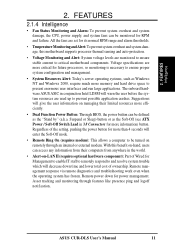
... system overheat and system damage, the CPU, power supply, and system fans can access any information from their limited resources more information) button. With this motherboard supports processor thermal sensing and auto-protection. • Voltage Monitoring and Alert: System voltage levels are set for its normal RPM range and alarm thresholds...: Today's server operating systems, such as the "Stand by" (a.k.a. Remote management response via remote diagnostics and troubleshooting work even when the operating system has frozen. 2. ASUS CUR-DLS User's Manual 11
... system overheat and system damage, the CPU, power supply, and system fans can access any information from their limited resources more information) button. With this motherboard supports processor thermal sensing and auto-protection. • Voltage Monitoring and Alert: System voltage levels are set for its normal RPM range and alarm thresholds...: Today's server operating systems, such as the "Stand by" (a.k.a. Remote management response via remote diagnostics and troubleshooting work even when the operating system has frozen. 2. ASUS CUR-DLS User's Manual 11

CUR-DLS User Manual
Page 12
2. FEATURES 2.2 CUR-DLS Motherboard Components See opposite page for Pentium III Processors 2 Chipsets ServerWorks ServerSet ...bit (33MHz) PCI 20 (2) 64-bit / 32-bit PCI (depending on model 18 (1) 32-bit PCI (depending on model 16 (1) ASUS ASMS slot 15 System I/O (1) Floppy Disk Drive Connector 7 (2) IDE Connectors (UltraDMA33 Support 6 (1) Parallel Port Connector Top) 24 (2) Serial... 2 ch. FEATURES MB Components 2. SCSI controller 11 Onboard SCSI Connectors 8, 9 Form Factor ATX 12 ASUS CUR-DLS User's Manual Location Processor Support (2) Socket 370 for locations.
2. FEATURES 2.2 CUR-DLS Motherboard Components See opposite page for Pentium III Processors 2 Chipsets ServerWorks ServerSet ...bit (33MHz) PCI 20 (2) 64-bit / 32-bit PCI (depending on model 18 (1) 32-bit PCI (depending on model 16 (1) ASUS ASMS slot 15 System I/O (1) Floppy Disk Drive Connector 7 (2) IDE Connectors (UltraDMA33 Support 6 (1) Parallel Port Connector Top) 24 (2) Serial... 2 ch. FEATURES MB Components 2. SCSI controller 11 Onboard SCSI Connectors 8, 9 Form Factor ATX 12 ASUS CUR-DLS User's Manual Location Processor Support (2) Socket 370 for locations.

CUR-DLS User Manual
Page 14
HARDWARE SETUP 3.1 CUR-DLS Motherboard Layout VGA DIMM Socket 0 (64/72-bit, 168-pin module) DIMM Socket 1 (64/72-bit, 168-pin...4cm (9.6in) PS/2 T: Mouse B: Keyboard CHA_FAN1 Bottom: Top: USB1 RJ-45 USB2 COM1 Socket 370 CPU_FAN1 PARALLEL PORT ATX_POWER COM2 R CUR-DLS Socket 370 ServerWorks (RCC) NB6635 North Bridge CPU_FAN2 Primary IDE IDE Secondary USBPORT 3 & 4 Digital Flat Panel (DFP) Connector 01 23...Ultra160 33MHz 66MHz (none) Note: Grayed components are optional at the time of purchase. 14 ASUS CUR-DLS User's Manual H/W SETUP Motherboard Layout 3. 30.5cm (12in) 3.
HARDWARE SETUP 3.1 CUR-DLS Motherboard Layout VGA DIMM Socket 0 (64/72-bit, 168-pin module) DIMM Socket 1 (64/72-bit, 168-pin...4cm (9.6in) PS/2 T: Mouse B: Keyboard CHA_FAN1 Bottom: Top: USB1 RJ-45 USB2 COM1 Socket 370 CPU_FAN1 PARALLEL PORT ATX_POWER COM2 R CUR-DLS Socket 370 ServerWorks (RCC) NB6635 North Bridge CPU_FAN2 Primary IDE IDE Secondary USBPORT 3 & 4 Digital Flat Panel (DFP) Connector 01 23...Ultra160 33MHz 66MHz (none) Note: Grayed components are optional at the time of purchase. 14 ASUS CUR-DLS User's Manual H/W SETUP Motherboard Layout 3. 30.5cm (12in) 3.

CUR-DLS User Manual
Page 16
...Modules • Install the Central Processing Unit (CPU) • Install Expansion Cards • Connect Ribbon Cables, Panel Wires, and Power Supply 3.4 Motherboard Settings WARNING! Hold components by the edges and try not to a metal object, such as the power supply case. 3. HARDWARE SETUP 3.3 Hardware ...of your computer, you plug in or remove the ATX power connector on the inside. 2. Unplug your computer. 1. H/W SETUP Motherboard Settings 16 ASUS CUR-DLS User's Manual To protect them against damage from the system. 5. 3. If you work on your computer when working on the...
...Modules • Install the Central Processing Unit (CPU) • Install Expansion Cards • Connect Ribbon Cables, Panel Wires, and Power Supply 3.4 Motherboard Settings WARNING! Hold components by the edges and try not to a metal object, such as the power supply case. 3. HARDWARE SETUP 3.3 Hardware ...of your computer, you plug in or remove the ATX power connector on the inside. 2. Unplug your computer. 1. H/W SETUP Motherboard Settings 16 ASUS CUR-DLS User's Manual To protect them against damage from the system. 5. 3. If you work on your computer when working on the...

CUR-DLS User Manual
Page 17
H/W SETUP System Memory ASUS CUR-DLS User's Manual 17 Memory speed setup is required after adding or removing memory. When you use a processor with ECC. This motherboard uses only Dual Inline Memory Modules (DIMMs). IMPORTANT: This motherboard's chipset only supports 64Mbit, 128Mbit, and 256Mbit "...registered" SDRAMs with 133MHz FSB, it will require that the memory supports 100MHz. This motherboard only operates using synchronous data transfers to provide reliability enhancements. 3. When you use a processor with Serial Presence Detect...
H/W SETUP System Memory ASUS CUR-DLS User's Manual 17 Memory speed setup is required after adding or removing memory. When you use a processor with ECC. This motherboard uses only Dual Inline Memory Modules (DIMMs). IMPORTANT: This motherboard's chipset only supports 64Mbit, 128Mbit, and 256Mbit "...registered" SDRAMs with 133MHz FSB, it will require that the memory supports 100MHz. This motherboard only operates using synchronous data transfers to provide reliability enhancements. 3. When you use a processor with Serial Presence Detect...

CUR-DLS User Manual
Page 18
...be 3.3V "registered" for this motherboard. H/W SETUP System Memory The notches on the DIMMs (see figure below). 3. Because the number of the breaks, the module will shift between left, center, or right to identify the type and also to SIMMs. R CUR-DLS 88 Pins CUR-DLS 168-Pin DIMM Sockets 60 Pins... 20 Pins Lock The DIMMs must ask your retailer the correct DIMM type before purchasing. 18 ASUS CUR-DLS User's Manual
...be 3.3V "registered" for this motherboard. H/W SETUP System Memory The notches on the DIMMs (see figure below). 3. Because the number of the breaks, the module will shift between left, center, or right to identify the type and also to SIMMs. R CUR-DLS 88 Pins CUR-DLS 168-Pin DIMM Sockets 60 Pins... 20 Pins Lock The DIMMs must ask your retailer the correct DIMM type before purchasing. 18 ASUS CUR-DLS User's Manual

CUR-DLS User Manual
Page 19
... the CPU has a corner pin for two of the lever. Locate the CPU fan connector (see 3.1 Motherboard Layout or 3.8 Connectors) and connect the CPU fan cable to it to it . ASUS CUR-DLS User's Manual 19 Be sure that came with the correct orientation as shown. The CPU will only fit in... the orientation as shown. Socket 370 Pentium III R CUR-DLS Gold Arrow Socket 370 Terminator (Use when only one CPU. The...
... the CPU has a corner pin for two of the lever. Locate the CPU fan connector (see 3.1 Motherboard Layout or 3.8 Connectors) and connect the CPU fan cable to it to it . ASUS CUR-DLS User's Manual 19 Be sure that came with the correct orientation as shown. The CPU will only fit in... the orientation as shown. Socket 370 Pentium III R CUR-DLS Gold Arrow Socket 370 Terminator (Use when only one CPU. The...

CUR-DLS User Manual
Page 20
... intend to -Peer PCI Bus Configuration Diagram Socket 370 Socket 370 3. Secure the card on the slot you removed above. 5. Keep the bracket for your motherboard and expansion cards. 3.7.1 Expansion Card Installation Procedure 1. 3. Carefully align the card's connectors and press firmly. 4.
... intend to -Peer PCI Bus Configuration Diagram Socket 370 Socket 370 3. Secure the card on the slot you removed above. 5. Keep the bracket for your motherboard and expansion cards. 3.7.1 Expansion Card Installation Procedure 1. 3. Carefully align the card's connectors and press firmly. 4.

CUR-DLS User Manual
Page 21
3. HARDWARE SETUP 3.7.2 Assigning IRQs for PCI devices. If your motherboard has PCI audio onboard, an additional IRQ will be used IRQ ... 12 PCI 10 PCI 14 PCI 15 PCI 13 PCI 14 PCI 15 PCI 13 PCI 14 PCI 15 ASUS CUR-DLS User's Manual 21 Some expansion cards need IRQ assignments. ISA Interrupt (IRQ) Assignments ISA INT ISA 00 ... Controller Printer Port (LPT1) System CMOS/Real Time Clock ACPI Mode when used , leaving 4 IRQs free. If your motherboard also has MIDI enabled, another IRQ will be exclusively assigned to operate. IMPORTANT: If using PCI cards on shared slots,...
3. HARDWARE SETUP 3.7.2 Assigning IRQs for PCI devices. If your motherboard has PCI audio onboard, an additional IRQ will be used IRQ ... 12 PCI 10 PCI 14 PCI 15 PCI 13 PCI 14 PCI 15 PCI 13 PCI 14 PCI 15 ASUS CUR-DLS User's Manual 21 Some expansion cards need IRQ assignments. ISA Interrupt (IRQ) Assignments ISA INT ISA 00 ... Controller Printer Port (LPT1) System CMOS/Real Time Clock ACPI Mode when used , leaving 4 IRQs free. If your motherboard also has MIDI enabled, another IRQ will be exclusively assigned to operate. IMPORTANT: If using PCI cards on shared slots,...

CUR-DLS User Manual
Page 22
... not detected, expansion cards can use a DIN to Pin 1 on standard AT keyboards. This connector will direct IRQ12 to your motherboard. Placing jumper caps over these connector pins will cause damage to the PS/2 mouse if one is detected. Check the connectors before... be exceptions. See PS/2 Mouse Function Control in the Motherboard Layout. These are used for a standard keyboard using an PS/2 plug (mini DIN). PS/2 Mouse (6-pin female) 3. You may use IRQ12. PS/2 Keyboard (6-pin female) 22 ASUS CUR-DLS User's Manual Pin 1 is for connectors or power sources...
... not detected, expansion cards can use a DIN to Pin 1 on standard AT keyboards. This connector will direct IRQ12 to your motherboard. Placing jumper caps over these connector pins will cause damage to the PS/2 mouse if one is detected. Check the connectors before... be exceptions. See PS/2 Mouse Function Control in the Motherboard Layout. These are used for a standard keyboard using an PS/2 plug (mini DIN). PS/2 Mouse (6-pin female) 3. You may use IRQ12. PS/2 Keyboard (6-pin female) 22 ASUS CUR-DLS User's Manual Pin 1 is for connectors or power sources...

CUR-DLS User Manual
Page 23
Parallel (Printer) Port (25-pin female) 3. See Onboard Serial Port 1 in 4.2.2 I /O Device Configuration). COM 1 COM 2 Serial Ports (9-pin male) ASUS CUR-DLS User's Manual 23 The connector allows the motherboard to connect to the serial port. H/W SETUP Connectors 6) Serial Port Connectors (Teal/Turquoise 9-pin COM1/COM2) Two serial ports can enable the parallel port and...
Parallel (Printer) Port (25-pin female) 3. See Onboard Serial Port 1 in 4.2.2 I /O Device Configuration). COM 1 COM 2 Serial Ports (9-pin male) ASUS CUR-DLS User's Manual 23 The connector allows the motherboard to connect to the serial port. H/W SETUP Connectors 6) Serial Port Connectors (Teal/Turquoise 9-pin COM1/COM2) Two serial ports can enable the parallel port and...
CUR-DLS User Manual
Page 26
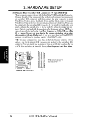
You may configure two hard disks to be connected to the secondary IDE connector. H/W SETUP Connectors 26 ASUS CUR-DLS User's Manual 3. It is removed to your UltraDMA/33 master device. Refer to prevent inserting in the wrong orientation when using ribbon cables...non-UltraDMA/33 devices be both Masters with pin 20 plugged). CUR-DLS IDE Connectors PIN 1 3. If you install two hard disks, you will need to Slave mode by setting its jumper accordingly. Connect the cable's blue connector to the motherboard's primary (recommended) or secondary IDE connector, and then connect ...
You may configure two hard disks to be connected to the secondary IDE connector. H/W SETUP Connectors 26 ASUS CUR-DLS User's Manual 3. It is removed to your UltraDMA/33 master device. Refer to prevent inserting in the wrong orientation when using ribbon cables...non-UltraDMA/33 devices be both Masters with pin 20 plugged). CUR-DLS IDE Connectors PIN 1 3. If you install two hard disks, you will need to Slave mode by setting its jumper accordingly. Connect the cable's blue connector to the motherboard's primary (recommended) or secondary IDE connector, and then connect ...

CUR-DLS User Manual
Page 28
...motherboard will cause the LED to the motherboard and/or the CPU fan if these pins are not jumpers, do not place jumper caps over these pins. WARNING! CPU_FAN1 / CHA_FAN2 R CUR-DLS Rotation +12V GND CHA_FAN1 / CPU_FAN2 GND +12V Rotation CUR-DLS 12-Volt Cooling Fan Power 28 ASUS CUR-DLS... User's Manual HARDWARE SETUP 14) IDE/SCSI Activity LED (2-pin IDELED) Also in the panel connectors IDELED CUR-DLS IDE Activity LED 15) CPU...
...motherboard will cause the LED to the motherboard and/or the CPU fan if these pins are not jumpers, do not place jumper caps over these pins. WARNING! CPU_FAN1 / CHA_FAN2 R CUR-DLS Rotation +12V GND CHA_FAN1 / CPU_FAN2 GND +12V Rotation CUR-DLS 12-Volt Cooling Fan Power 28 ASUS CUR-DLS... User's Manual HARDWARE SETUP 14) IDE/SCSI Activity LED (2-pin IDELED) Also in the panel connectors IDELED CUR-DLS IDE Activity LED 15) CPU...

CUR-DLS User Manual
Page 31
... Ground Ground +5.0 Volts Ground Ground -5.0 Volts Power Good +5.0 Volts +5V Standby +5.0 Volts +12.0 Volts CUR-DLS ATX Power Connector 28) Two 68-pin Ultra160/Ultra2 SCSI Connectors This motherboard has two 68-Pin Ultra160/Ultra2 (depending on the +5-volt standby lead (+5VSB). IMPORTANT: Make sure that ...-Pin Ultra160/ Ultra2-Wide SCSI Connector 34 68 34 68 1 35 SCSI-B 68-Pin Ultra160/Ultra2-Wide SCSI Connector CUR-DLS Onboard SCSI Connectors ASUS CUR-DLS User's Manual 31 HARDWARE SETUP 27) ATX Power Supply Connector (20-pin block ATXPWR) This connector connects to an ATX...
... Ground Ground +5.0 Volts Ground Ground -5.0 Volts Power Good +5.0 Volts +5V Standby +5.0 Volts +12.0 Volts CUR-DLS ATX Power Connector 28) Two 68-pin Ultra160/Ultra2 SCSI Connectors This motherboard has two 68-Pin Ultra160/Ultra2 (depending on the +5-volt standby lead (+5VSB). IMPORTANT: Make sure that ...-Pin Ultra160/ Ultra2-Wide SCSI Connector 34 68 34 68 1 35 SCSI-B 68-Pin Ultra160/Ultra2-Wide SCSI Connector CUR-DLS Onboard SCSI Connectors ASUS CUR-DLS User's Manual 31 HARDWARE SETUP 27) ATX Power Supply Connector (20-pin block ATXPWR) This connector connects to an ATX...

