CUBX User Manual
Page 4
... Organized 7 1.2 Item Checklist 7 2. FEATURES 8 2.1 The ASUS CUBX Motherboard 8 2.1.1 Specifications 8 2.1.2 Special Features 10 2.1.3 Performance Features 10 2.1.4 Intelligence 11 2.2 CUBX Motherboard Components 12 2.2.1 Component Locations 13 3. HARDWARE SETUP 14 3.1 CUBX Motherboard Layout 14 3.2 Layout Contents 15 3.3 Hardware Setup Procedure 17 3.4 Motherboard Settings 17 3.5 System Memory (DIMM 22 3.5.1 General DIMM Notes 22 3.5.2 Memory Installation 23 3.6 Central Processing Unit (CPU...
... Organized 7 1.2 Item Checklist 7 2. FEATURES 8 2.1 The ASUS CUBX Motherboard 8 2.1.1 Specifications 8 2.1.2 Special Features 10 2.1.3 Performance Features 10 2.1.4 Intelligence 11 2.2 CUBX Motherboard Components 12 2.2.1 Component Locations 13 3. HARDWARE SETUP 14 3.1 CUBX Motherboard Layout 14 3.2 Layout Contents 15 3.3 Hardware Setup Procedure 17 3.4 Motherboard Settings 17 3.5 System Memory (DIMM 22 3.5.1 General DIMM Notes 22 3.5.2 Memory Installation 23 3.6 Central Processing Unit (CPU...

CUBX User Manual
Page 8
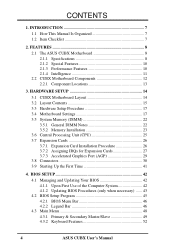
... an Accelerated Graphics Port card for virtually automatic setup. • PC100 Memory Support: Equipped with I /O: Provides two high-speed UART compatible serial ports and one ISA or six PCI with EPP and ECP capabilities. 8 ASUS CUBX User's Manual 2. FEATURES 2.1 The ASUS CUBX Motherboard The ASUS CUBX is carefully designed for the demanding PC user who wants advanced...
... an Accelerated Graphics Port card for virtually automatic setup. • PC100 Memory Support: Equipped with I /O: Provides two high-speed UART compatible serial ports and one ISA or six PCI with EPP and ECP capabilities. 8 ASUS CUBX User's Manual 2. FEATURES 2.1 The ASUS CUBX Motherboard The ASUS CUBX is carefully designed for the demanding PC user who wants advanced...

CUBX User Manual
Page 10
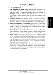
.... 2.1.3 Performance Features • Concurrent PCI: Concurrent PCI allows multiple PCI transfers from PCI master busses to the memory and processor. • High-Speed Data Transfer Interface: IDE transfers using PC100-compliant SDRAM. 10 ASUS CUBX User's Manual The new PC'99 requirements for systems and components are based on the following high-level...
.... 2.1.3 Performance Features • Concurrent PCI: Concurrent PCI allows multiple PCI transfers from PCI master busses to the memory and processor. • High-Speed Data Transfer Interface: IDE transfers using PC100-compliant SDRAM. 10 ASUS CUBX User's Manual The new PC'99 requirements for systems and components are based on the following high-level...
CUBX User Manual
Page 11
... than 4 seconds when the system is necessary to prevent possible application crashes. ASUS CUBX User's Manual 11 Through the way a particular LED illuminates, the user can be turned on managing their computers from a fax/modem. All fans are more memory and hard drive space to critical motherboard components. Suggestions will warn the user...
... than 4 seconds when the system is necessary to prevent possible application crashes. ASUS CUBX User's Manual 11 Through the way a particular LED illuminates, the user can be turned on managing their computers from a fax/modem. All fans are more memory and hard drive space to critical motherboard components. Suggestions will warn the user...

CUBX User Manual
Page 12
... Support Socket 370 for locations. FEATURES 2.2 CUBX Motherboard Components See opposite page for Pentium III/Celeron Processors 1 Feature Setting DIP Switches 8 100/66MHz system bus (Frequency Multiples 2.0-8.0) Chipsets Intel 440BX AGPset 3 Multi-I/O Chipset 16 Main Memory Maximum 1GB Supported 4 DIMM Sockets 4 PC100... Features Wake-On-LAN Connector 15 Wake-On-Ring Connector 13 Hardware Monitoring System Voltage Monitoring (integrated in ASUS ASIC) ......... 7 3 Fan Power and Speed Monitoring Connectors Power ATX Power Supply Connector 2 Special Features Onboard Power LED 11...
... Support Socket 370 for locations. FEATURES 2.2 CUBX Motherboard Components See opposite page for Pentium III/Celeron Processors 1 Feature Setting DIP Switches 8 100/66MHz system bus (Frequency Multiples 2.0-8.0) Chipsets Intel 440BX AGPset 3 Multi-I/O Chipset 16 Main Memory Maximum 1GB Supported 4 DIMM Sockets 4 PC100... Features Wake-On-LAN Connector 15 Wake-On-Ring Connector 13 Hardware Monitoring System Voltage Monitoring (integrated in ASUS ASIC) ......... 7 3 Fan Power and Speed Monitoring Connectors Power ATX Power Supply Connector 2 Special Features Onboard Power LED 11...

CUBX User Manual
Page 15
... Bus Frequency Setting 4) DSW 5-10 p. 20 CPU External Frequency Selection 5) DSW 1-4 p. 21 CPU Core:BUS Frequency Multiple Selection Expansion Slots/Sockets 1) System Memory p.22 System Memory Support 2) DIMM1/2/3/4 p.22 DIMM Memory Module Support 3) Socket 370 p.25 CPU Support 4) PCI1/2/3/4/5/6 p.27 32-bit PCI Bus Expansion Slots 5) ISA1 p.27 16-bit ISA Bus Expansion... (PANEL) p. 38 Keyboard Lock Switch Lead (2 pins) 20) SPEAKER (PANEL) p. 38 System Warning Speaker Connector (4 pins) 21) MSG.LED (PANEL) p. 38 System Message LED (2 pins) ASUS CUBX User's Manual 15
... Bus Frequency Setting 4) DSW 5-10 p. 20 CPU External Frequency Selection 5) DSW 1-4 p. 21 CPU Core:BUS Frequency Multiple Selection Expansion Slots/Sockets 1) System Memory p.22 System Memory Support 2) DIMM1/2/3/4 p.22 DIMM Memory Module Support 3) Socket 370 p.25 CPU Support 4) PCI1/2/3/4/5/6 p.27 32-bit PCI Bus Expansion Slots 5) ISA1 p.27 16-bit ISA Bus Expansion... (PANEL) p. 38 Keyboard Lock Switch Lead (2 pins) 20) SPEAKER (PANEL) p. 38 System Warning Speaker Connector (4 pins) 21) MSG.LED (PANEL) p. 38 System Message LED (2 pins) ASUS CUBX User's Manual 15
CUBX User Manual
Page 17
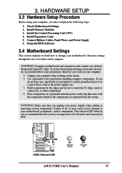
... have one, touch both of switches and/or jumpers. Install Memory Modules 3. Setup the BIOS Software 3.4 Motherboard Settings This section explains in suspend or soft-off mode and not powered OFF. ® CUBX CUBX Onboard LED ON Standby Power OFF Powered Off ASUS CUBX User's Manual 17 Hold components by the edges and try not...
... have one, touch both of switches and/or jumpers. Install Memory Modules 3. Setup the BIOS Software 3.4 Motherboard Settings This section explains in suspend or soft-off mode and not powered OFF. ® CUBX CUBX Onboard LED ON Standby Power OFF Powered Off ASUS CUBX User's Manual 17 Hold components by the edges and try not...
CUBX User Manual
Page 22
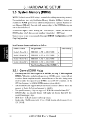
... higher pin density than EDO (Ex- H/W SETUP System Memory 3. Sockets are generally thinner with 9 chips per side (standard 8 chips/side + 1 ECC chip). Memory speed setup is recommended through SDRAM Configuration in 32, 64, 128, 256MB. 22 ASUS CUBX User's Manual double-sided come in 16, 32, 64...,128MB; This motherboard uses only Dual Inline Memory Modules (DIMMs). Install memory in any combination as follows: DIMM Location 168-pin DIMM Total Memory Socket 1 (Rows 0&1) SDRAM 8, 16, 32,...
... higher pin density than EDO (Ex- H/W SETUP System Memory 3. Sockets are generally thinner with 9 chips per side (standard 8 chips/side + 1 ECC chip). Memory speed setup is recommended through SDRAM Configuration in 32, 64, 128, 256MB. 22 ASUS CUBX User's Manual double-sided come in 16, 32, 64...,128MB; This motherboard uses only Dual Inline Memory Modules (DIMMs). Install memory in any combination as follows: DIMM Location 168-pin DIMM Total Memory Socket 1 (Rows 0&1) SDRAM 8, 16, 32,...
CUBX User Manual
Page 23
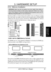
...on the DIMMs (see 3.3 Hardware Setup Procedure for more information). HARDWARE SETUP 3.5.2 Memory Installation WARNING! SDRAM DIMMs have a higher pin density. This motherboard supports four clock signals per DIMM. H/W SETUP System Memory The notches on the DIMM will shift between left, center, or right to identify ... damage to prevent the wrong type from being inserted into the DIMM slot on either side of pins are different on the motherboard. ASUS CUBX User's Manual 23 Insert the module(s) as shown. Because the number of the breaks, the module will only fit in the orientation...
...on the DIMMs (see 3.3 Hardware Setup Procedure for more information). HARDWARE SETUP 3.5.2 Memory Installation WARNING! SDRAM DIMMs have a higher pin density. This motherboard supports four clock signals per DIMM. H/W SETUP System Memory The notches on the DIMM will shift between left, center, or right to identify ... damage to prevent the wrong type from being inserted into the DIMM slot on either side of pins are different on the motherboard. ASUS CUBX User's Manual 23 Insert the module(s) as shown. Because the number of the breaks, the module will only fit in the orientation...
CUBX User Manual
Page 24
HARDWARE SETUP (This page was intentionally left blank.) 3. 3. H/W SETUP System Memory 24 ASUS CUBX User's Manual
HARDWARE SETUP (This page was intentionally left blank.) 3. 3. H/W SETUP System Memory 24 ASUS CUBX User's Manual

CUBX User Manual
Page 28
... any available slot on your used and free IRQs in Windows 98, the Control Panel icon in use a DMA (Direct Memory Access) channel. System IRQs are available to reserve). 28 ASUS CUBX User's Manual To see a map of the BIOS setup utility can contact your system. Double-clicking on this motherboard are set...
... any available slot on your used and free IRQs in Windows 98, the Control Panel icon in use a DMA (Direct Memory Access) channel. System IRQs are available to reserve). 28 ASUS CUBX User's Manual To see a map of the BIOS setup utility can contact your system. Double-clicking on this motherboard are set...
CUBX User Manual
Page 29
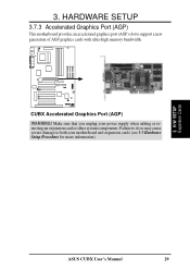
Make sure that you unplug your motherboard and expansion cards (see 3.3 Hardware Setup Procedure for more information). ® CUBX 3. H/W SETUP Expansion Cards ASUS CUBX User's Manual 29 Failure to do so may cause severe damage to support a new generation of AGP graphics cards with ultra-high memory bandwidth. CUBX Accelerated Graphics Port (AGP) WARNING! 3. HARDWARE SETUP 3.7.3 Accelerated Graphics Port (AGP) This motherboard provides an accelerated graphics port (AGP) slot to both your power supply when adding or removing an expansion card or other system components.
Make sure that you unplug your motherboard and expansion cards (see 3.3 Hardware Setup Procedure for more information). ® CUBX 3. H/W SETUP Expansion Cards ASUS CUBX User's Manual 29 Failure to do so may cause severe damage to support a new generation of AGP graphics cards with ultra-high memory bandwidth. CUBX Accelerated Graphics Port (AGP) WARNING! 3. HARDWARE SETUP 3.7.3 Accelerated Graphics Port (AGP) This motherboard provides an accelerated graphics port (AGP) slot to both your power supply when adding or removing an expansion card or other system components.
CUBX User Manual
Page 41
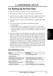
... High frequency beeps when system is working Meaning No error during POST No DRAM installed or detected Video card not found or video card memory bad CPU overheated System running , the BIOS will alarm beeps or additional messages will light. Be sure that is pressed. While the ... HARDWARE SETUP 3.9 Starting Up the First Time 1. Connect the power supply cord into a power outlet that all connections are running at a lower frequency ASUS CUBX User's Manual 41 Connect the power cord into the power supply located on the back of your system case according to switch on the power...
... High frequency beeps when system is working Meaning No error during POST No DRAM installed or detected Video card not found or video card memory bad CPU overheated System running , the BIOS will alarm beeps or additional messages will light. Be sure that is pressed. While the ... HARDWARE SETUP 3.9 Starting Up the First Time 1. Connect the power supply cord into a power outlet that all connections are running at a lower frequency ASUS CUBX User's Manual 41 Connect the power cord into the power supply located on the back of your system case according to switch on the power...

CUBX User Manual
Page 42
... therefore, cannot be programmed by uploading a new BIOS file to reinstall the BIOS later. If "unknown" is displayed after Flash Memory:, the memory chip is either not programmable or is your motherboard, check the last four numbers of the code displayed on the motherboard. AFLASH.... to the programmable flash ROM on the upper lefthand corner of the original motherboard BIOS along with certain memory drivers that updates the BIOS by the Flash Memory Writer utility. 42 ASUS CUBX User's Manual In DOS mode, type A:\AFLASH to the just created boot disk. Larger numbers represent...
... therefore, cannot be programmed by uploading a new BIOS file to reinstall the BIOS later. If "unknown" is displayed after Flash Memory:, the memory chip is either not programmable or is your motherboard, check the last four numbers of the code displayed on the motherboard. AFLASH.... to the programmable flash ROM on the upper lefthand corner of the original motherboard BIOS along with certain memory drivers that updates the BIOS by the Flash Memory Writer utility. 42 ASUS CUBX User's Manual In DOS mode, type A:\AFLASH to the just created boot disk. Larger numbers represent...
CUBX User Manual
Page 44
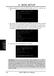
... updating. BIOS SETUP Updating BIOS WARNING! If the Flash Memory Writer utility was not able to boot up . If this might prevent your system from booting up . Follow the onscreen instructions to start the update. 7. The boot block will need servicing. 44 ASUS CUBX User's Manual When prompted to confirm the BIOS update...
... updating. BIOS SETUP Updating BIOS WARNING! If the Flash Memory Writer utility was not able to boot up . If this might prevent your system from booting up . Follow the onscreen instructions to start the update. 7. The boot block will need servicing. 44 ASUS CUBX User's Manual When prompted to confirm the BIOS update...
CUBX User Manual
Page 53
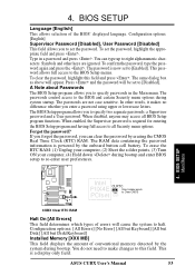
...which types of errors will appear. BIOS SETUP Main Menu Intel PIIX4E CLRTC Short solder points to specify passwords in a password and press . ASUS CUBX User's Manual 53 To set the password. To confirm the password, type the password again and press the . To clear the password,...this field and press . Configuration options: [All Errors] [No Error] [All but Keyboard] [All but Disk] [All but Disk/Keyboard] Installed Memory [XXX MB] This field displays the amount of the BIOS' displayed language. This password allows full access to specify two separate passwords: a Supervisor ...
...which types of errors will appear. BIOS SETUP Main Menu Intel PIIX4E CLRTC Short solder points to specify passwords in a password and press . ASUS CUBX User's Manual 53 To set the password. To confirm the password, type the password again and press the . To clear the password,...this field and press . Configuration options: [All Errors] [No Error] [All but Keyboard] [All but Disk] [All but Disk/Keyboard] Installed Memory [XXX MB] This field displays the amount of the BIOS' displayed language. This password allows full access to specify two separate passwords: a Supervisor ...

CUBX User Manual
Page 55
... added to every Pentium III processor to detect a USB device on or off the CPU's Level 1 and Level 2 built-in cache. BIOS SETUP Advanced Menu ASUS CUBX User's Manual 55 BIOS SETUP CPU Vcore This field displays the core voltage supplied to supply the processor with installed DRAM of greater than 64MB... Processor Serial Number is a unique number that is not detected. [Enabled] will always reserve IRQ12, whether on [Disabled]. Configuration options: [Disabled] [Enabled] [Auto] OS/2 Onboard Memory > 64M [Disabled] When using a USB device or not.
... added to every Pentium III processor to detect a USB device on or off the CPU's Level 1 and Level 2 built-in cache. BIOS SETUP Advanced Menu ASUS CUBX User's Manual 55 BIOS SETUP CPU Vcore This field displays the core voltage supplied to supply the processor with installed DRAM of greater than 64MB... Processor Serial Number is a unique number that is not detected. [Enabled] will always reserve IRQ12, whether on [Disabled]. Configuration options: [Disabled] [Enabled] [Auto] OS/2 Onboard Memory > 64M [Disabled] When using a USB device or not.
CUBX User Manual
Page 58
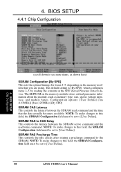
NOTE: To make changes to this field, the SDRAM Configuration field must be set to [User Define]. 58 ASUS CUBX User's Manual The default setting is [By SPD], which configures items 2-5 by reading the contents in the SPD (Serial Presence Detect) device. NOTE: To...the idle clocks after issuing a precharge command to CAS Delay This controls the latency between the SDRAM read /write command. 4. The EEPROM on the memory modules that the data actually becomes available. NOTE: To make changes to this field, the SDRAM Configuration field must be set to [User Define]. ...
NOTE: To make changes to this field, the SDRAM Configuration field must be set to [User Define]. 58 ASUS CUBX User's Manual The default setting is [By SPD], which configures items 2-5 by reading the contents in the SPD (Serial Presence Detect) device. NOTE: To...the idle clocks after issuing a precharge command to CAS Delay This controls the latency between the SDRAM read /write command. 4. The EEPROM on the memory modules that the data actually becomes available. NOTE: To make changes to this field, the SDRAM Configuration field must be set to [User Define]. ...
CUBX User Manual
Page 59
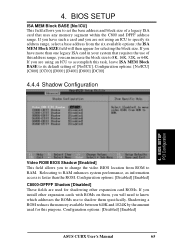
... Size [64MB] This feature allows you to this feature; Configuration options: [4MB] [8MB] [16MB] [32MB] [64MB] [128MB] [256MB] Video Memory Cache Mode [UC] USWC (uncacheable, speculative write combining) is a cache technology for AGP graphic data. Configuration options: [Disabled] [Enabled] Onboard PCI IDE.... Configuration options: [Disabled] [Enabled] Memory Hole At 15M-16M [Disabled] This field allows you to enable the primary IDE channel, secondary IDE channel, both, or disable both channels. BIOS SETUP Chip Configuration ASUS CUBX User's Manual 59 4. Leave on default...
... Size [64MB] This feature allows you to this feature; Configuration options: [4MB] [8MB] [16MB] [32MB] [64MB] [128MB] [256MB] Video Memory Cache Mode [UC] USWC (uncacheable, speculative write combining) is a cache technology for AGP graphic data. Configuration options: [Disabled] [Enabled] Onboard PCI IDE.... Configuration options: [Disabled] [Enabled] Memory Hole At 15M-16M [Disabled] This field allows you to enable the primary IDE channel, secondary IDE channel, both, or disable both channels. BIOS SETUP Chip Configuration ASUS CUBX User's Manual 59 4. Leave on default...
CUBX User Manual
Page 65
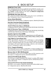
...as information access is faster than one legacy ISA card in your system that uses any memory segment within the C800 and DFFF address range. If you to RAM. Shadowing a ROM reduces the memory available between 640K and 1024K by the amount used for selecting the block size. 4. ...BIOS SETUP ISA MEM Block BASE [No/ICU] This field allows you are using an ICU to specify its default setting of this purpose. Configuration options: [Disabled] [Enabled] ASUS CUBX User's Manual 65...
...as information access is faster than one legacy ISA card in your system that uses any memory segment within the C800 and DFFF address range. If you to RAM. Shadowing a ROM reduces the memory available between 640K and 1024K by the amount used for selecting the block size. 4. ...BIOS SETUP ISA MEM Block BASE [No/ICU] This field allows you are using an ICU to specify its default setting of this purpose. Configuration options: [Disabled] [Enabled] ASUS CUBX User's Manual 65...


