AT5IONT-I User's manual
Page 3
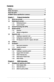
...this guide vi AT5IONT-I Series specifications summary viii Chapter 1: Product introduction 1.1 Before you proceed 1-1 1.2 Motherboard overview 1-2 1.2.1 Motherboard layout 1-2 1.2.2 Layout contents 1-3 1.3 Central Processing Unit (CPU 1-3 1.4 System memory 1-3 1.4.1 Overview 1-3 1.4.2 Memory configurations 1-4 ... DVD information 1-14 1.8.3 ASUS VideoSecurity 1-15 1.8.4 ASUS Home Theater Gate 1-17 1.8.5 ASUS @Vibe 1-20 Chapter 2: BIOS information 2.1 Managing and updating your BIOS 2-1 2.1.1 ASUS Update utility 2-1 2.1.2 ASUS EZ Flash 2 2-2 2.1.3 ASUS CrashFree BIOS 2-3 iii
...this guide vi AT5IONT-I Series specifications summary viii Chapter 1: Product introduction 1.1 Before you proceed 1-1 1.2 Motherboard overview 1-2 1.2.1 Motherboard layout 1-2 1.2.2 Layout contents 1-3 1.3 Central Processing Unit (CPU 1-3 1.4 System memory 1-3 1.4.1 Overview 1-3 1.4.2 Memory configurations 1-4 ... DVD information 1-14 1.8.3 ASUS VideoSecurity 1-15 1.8.4 ASUS Home Theater Gate 1-17 1.8.5 ASUS @Vibe 1-20 Chapter 2: BIOS information 2.1 Managing and updating your BIOS 2-1 2.1.1 ASUS Update utility 2-1 2.1.2 ASUS EZ Flash 2 2-2 2.1.3 ASUS CrashFree BIOS 2-3 iii
AT5IONT-I User's manual
Page 8
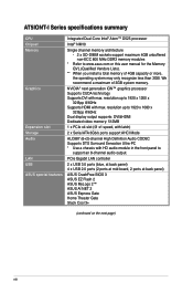
... on the next page) viii We recommend a maximum of 4GB capacity or more, the operating system may only recognize less than 3GB. AT5IONT-I Series specifications summary CPU Chipset Memory Graphics Expansion slot Storage Audio LAN USB ASUS special features Integrated Dual-Core Intel® Atom™ D525 processor Intel® NM10 Single channel...
... on the next page) viii We recommend a maximum of 4GB capacity or more, the operating system may only recognize less than 3GB. AT5IONT-I Series specifications summary CPU Chipset Memory Graphics Expansion slot Storage Audio LAN USB ASUS special features Integrated Dual-Core Intel® Atom™ D525 processor Intel® NM10 Single channel...
AT5IONT-I User's manual
Page 12
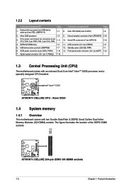
...) 1-1 6. Clear RTC RAM (3-pin CLRTC) 1-6 2. Internal speaker connector (4-pin SPEAKER) 1-12 3. Serial ATA connectors (7-pin SATA1/2) 1-10 4. D525 AT5IONT-I DELUXE AT5IONT-I DELUXE 204-pin DDR3 SO-DIMM sockets 1-3 Chapter 1: Product introduction Atom D525 1.4 System memory 1.4.1 Overview This motherboard comes with an onboard Dual-Core Intel® Atom™ D525 processor and a specially designed...
...) 1-1 6. Clear RTC RAM (3-pin CLRTC) 1-6 2. Internal speaker connector (4-pin SPEAKER) 1-12 3. Serial ATA connectors (7-pin SATA1/2) 1-10 4. D525 AT5IONT-I DELUXE AT5IONT-I DELUXE 204-pin DDR3 SO-DIMM sockets 1-3 Chapter 1: Product introduction Atom D525 1.4 System memory 1.4.1 Overview This motherboard comes with an onboard Dual-Core Intel® Atom™ D525 processor and a specially designed...
AT5IONT-I User's manual
Page 13
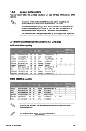
...SSY3128MB-EDJED 1GB DS APACER HYNIX HYNIX KTC ELPIDA ELPIDA Chip NO. Timing Voltage AM5D5808AEWSBG 9 - D1288JELDPGD9U - - AT5IONT-I Series 1-4 ASUS AT5IONT-I Series Motherboard Qualified Vendors Lists (QVL) DDR3-1067 MHz capability Vendors Part No. Size APACER AS01GFA06C7NBGC 1GB HYNIX...asus.com for the OS can be about 3GB or less. H5TQ2G83BFR - - For optimum compatibility, it is recommended that you install 4GB or more memory on AT5IONT-I Series motherboards. H5TQ1G83TFR - - Visit the ASUS website at 800MHz on the motherboard, the actual usable memory...
...SSY3128MB-EDJED 1GB DS APACER HYNIX HYNIX KTC ELPIDA ELPIDA Chip NO. Timing Voltage AM5D5808AEWSBG 9 - D1288JELDPGD9U - - AT5IONT-I Series 1-4 ASUS AT5IONT-I Series Motherboard Qualified Vendors Lists (QVL) DDR3-1067 MHz capability Vendors Part No. Size APACER AS01GFA06C7NBGC 1GB HYNIX...asus.com for the OS can be about 3GB or less. H5TQ2G83BFR - - For optimum compatibility, it is recommended that you install 4GB or more memory on AT5IONT-I Series motherboards. H5TQ1G83TFR - - Visit the ASUS website at 800MHz on the motherboard, the actual usable memory...
AT5IONT-I User's manual
Page 15
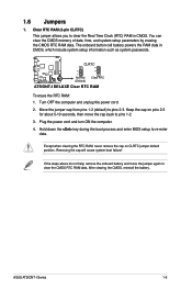
...pins 1-2 (default) to re-enter data. Plug the power cord and turn ON the computer. 4. ASUS AT5IONT-I DELUXE Clear RTC RAM To erase the RTC RAM: 1. You can clear the CMOS memory of date, time, and system setup parameters by erasing the CMOS RTC RAM data. If the steps... never remove the cap on pins 2-3 for about 5-10 seconds, then move the jumper again to pins 1-2. 3. CLRTC 12 23 AT5IONT-I DELUXE Normal (Default) Clear RTC AT5IONT-I Series 1-6 1.6 Jumpers 1. The onboard button cell battery powers the RAM data in CMOS. Hold down the key during the boot ...
...pins 1-2 (default) to re-enter data. Plug the power cord and turn ON the computer. 4. ASUS AT5IONT-I DELUXE Clear RTC RAM To erase the RTC RAM: 1. You can clear the CMOS memory of date, time, and system setup parameters by erasing the CMOS RTC RAM data. If the steps... never remove the cap on pins 2-3 for about 5-10 seconds, then move the jumper again to pins 1-2. 3. CLRTC 12 23 AT5IONT-I DELUXE Normal (Default) Clear RTC AT5IONT-I Series 1-6 1.6 Jumpers 1. The onboard button cell battery powers the RAM data in CMOS. Hold down the key during the boot ...
AT5IONT-I User's manual
Page 36
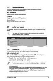
... options: Manual - Select either one of CPU overclocking options to achieve desired CPU internal frequency. System Memory Displays the auto-detected system memory. 2.4 Advanced menu The Advanced menu items allow you set overclocking parameters. Take caution when changing the ...AI Overclocking item to adjust the CPU frequency. The BIOS automatically detects the items in this menu. Main Advanced AT5IONT-I Series 2-7 ASUS AT5IONT-I DELUXE BIOS Setup Power Boot Tools Exit JumperFree CPU Configuration Chipset Onboard Devices Configuration USB Configuration PCIPnP Version 0214 ...
... options: Manual - Select either one of CPU overclocking options to achieve desired CPU internal frequency. System Memory Displays the auto-detected system memory. 2.4 Advanced menu The Advanced menu items allow you set overclocking parameters. Take caution when changing the ...AI Overclocking item to adjust the CPU frequency. The BIOS automatically detects the items in this menu. Main Advanced AT5IONT-I Series 2-7 ASUS AT5IONT-I DELUXE BIOS Setup Power Boot Tools Exit JumperFree CPU Configuration Chipset Onboard Devices Configuration USB Configuration PCIPnP Version 0214 ...
AT5IONT-I User's manual
Page 37
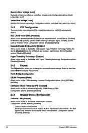
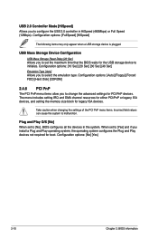
...] 2.4.3 Chipset The Chipset menu allows you to enable or disable configurating DRAM Timing by SPD [Enabled] Allows you to Auto for safe mode. Memory Over Voltage [Auto] Manually set memory voltage or set to change the advanced chipset settings. Configuration options: [Auto] [+47mV] [+94mV] [+141mV] 2.4.2 CPU Configuration The items in the onboard...
...] 2.4.3 Chipset The Chipset menu allows you to enable or disable configurating DRAM Timing by SPD [Enabled] Allows you to Auto for safe mode. Memory Over Voltage [Auto] Manually set memory voltage or set to change the advanced chipset settings. Configuration options: [Auto] [+47mV] [+94mV] [+141mV] 2.4.2 CPU Configuration The items in the onboard...
AT5IONT-I User's manual
Page 39
... settings for legacy ISA devices. The menu includes setting IRQ and DMA channel resources for either PCI/PnP or legacy ISA devices, and setting the memory size block for PCI/PnP devices. Plug and Play O/S [No] When set to [Yes] and if you to initialize.
... settings for legacy ISA devices. The menu includes setting IRQ and DMA channel resources for either PCI/PnP or legacy ISA devices, and setting the memory size block for PCI/PnP devices. Plug and Play O/S [No] When set to [Yes] and if you to initialize.


