AT5IONT-I User's manual
Page 3
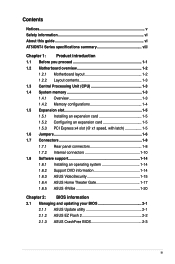
Contents Notices...v Safety information vi About this guide vi AT5IONT-I Series specifications summary viii Chapter 1: Product introduction 1.1 Before you proceed 1-1 1.2 Motherboard overview 1-2 1.2.1 Motherboard layout 1-2 1.2.2 ... 1-10 1.8 Software support 1-14 1.8.1 Installing an operating system 1-14 1.8.2 Support DVD information 1-14 1.8.3 ASUS VideoSecurity 1-15 1.8.4 ASUS Home Theater Gate 1-17 1.8.5 ASUS @Vibe 1-20 Chapter 2: BIOS information 2.1 Managing and updating your BIOS 2-1 2.1.1 ASUS Update utility 2-1 2.1.2 ASUS EZ Flash 2 2-2 2.1.3 ASUS CrashFree BIOS 2-3 iii
Contents Notices...v Safety information vi About this guide vi AT5IONT-I Series specifications summary viii Chapter 1: Product introduction 1.1 Before you proceed 1-1 1.2 Motherboard overview 1-2 1.2.1 Motherboard layout 1-2 1.2.2 ... 1-10 1.8 Software support 1-14 1.8.1 Installing an operating system 1-14 1.8.2 Support DVD information 1-14 1.8.3 ASUS VideoSecurity 1-15 1.8.4 ASUS Home Theater Gate 1-17 1.8.5 ASUS @Vibe 1-20 Chapter 2: BIOS information 2.1 Managing and updating your BIOS 2-1 2.1.1 ASUS Update utility 2-1 2.1.2 ASUS EZ Flash 2 2-2 2.1.3 ASUS CrashFree BIOS 2-3 iii

AT5IONT-I User's manual
Page 4
Contents 2.2 BIOS setup program 2-4 2.3 Main menu 2-4 2.3.1 System Time 2-5 2.3.2 System Date 2-5 2.3.3 SATA 1~2 2-5 2.3.4 Storage Configuration 2-6 2.3.5 3rd Party Storage Configuration 2-6 2.3.6 System Information 2-7 2.4 Advanced menu 2-7 2.4.1 JumperFree 2-7 2.4.2 CPU Configuration 2-8 2.4.3 Chipset 2-8 2.4.4...2-11 2.5.4 APM Configuration 2-11 2.5.5 Hardware Monitor 2-12 2.6 Boot menu 2-12 2.6.1 Boot Device Priority 2-12 2.6.2 Boot Settings Configuration 2-13 2.6.3 Security 2-13 2.7 Tools menu 2-15 2.7.1 ASUS EZ Flash 2 2-15 2.7.2 Express Gate 2-15 2.8 Exit menu 2-16 iv
Contents 2.2 BIOS setup program 2-4 2.3 Main menu 2-4 2.3.1 System Time 2-5 2.3.2 System Date 2-5 2.3.3 SATA 1~2 2-5 2.3.4 Storage Configuration 2-6 2.3.5 3rd Party Storage Configuration 2-6 2.3.6 System Information 2-7 2.4 Advanced menu 2-7 2.4.1 JumperFree 2-7 2.4.2 CPU Configuration 2-8 2.4.3 Chipset 2-8 2.4.4...2-11 2.5.4 APM Configuration 2-11 2.5.5 Hardware Monitor 2-12 2.6 Boot menu 2-12 2.6.1 Boot Device Priority 2-12 2.6.2 Boot Settings Configuration 2-13 2.6.3 Security 2-13 2.7 Tools menu 2-15 2.7.1 ASUS EZ Flash 2 2-15 2.7.2 Express Gate 2-15 2.8 Exit menu 2-16 iv
AT5IONT-I User's manual
Page 6
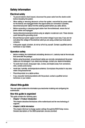
...using an adapter or extension cord. How this guide This user guide contains the information you are not sure about the voltage of the BIOS parameters are using the product, ensure that all power cables from the existing system before you detect any area where it may become wet.... • If the power supply is broken, do not try to fix it supports. • Chapter 2: BIOS information This chapter tells how to change system settings through the BIOS Setup menus. If possible, disconnect all cables are correctly connected and the power cables are connected. vi Operation safety ...
...using an adapter or extension cord. How this guide This user guide contains the information you are not sure about the voltage of the BIOS parameters are using the product, ensure that all power cables from the existing system before you detect any area where it may become wet.... • If the power supply is broken, do not try to fix it supports. • Chapter 2: BIOS information This chapter tells how to change system settings through the BIOS Setup menus. If possible, disconnect all cables are correctly connected and the power cables are connected. vi Operation safety ...
AT5IONT-I User's manual
Page 8
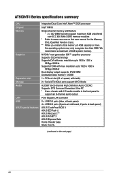
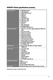
... controller 2 x USB 3.0 ports (blue, at back panel) 4 x USB 2.0 ports (2 ports at mid-board, 2 ports at back panel) ASUS CrashFree BIOS 3 ASUS EZ Flash 2 ASUS MyLogo 2™ ASUS AI NET 2 ASUS Express Gate Home Theater Gate Stack Cool 3+ (continued on the next page) viii AT5IONT-I Series specifications summary CPU Chipset Memory Graphics Expansion slot Storage Audio LAN USB...
... controller 2 x USB 3.0 ports (blue, at back panel) 4 x USB 2.0 ports (2 ports at mid-board, 2 ports at back panel) ASUS CrashFree BIOS 3 ASUS EZ Flash 2 ASUS MyLogo 2™ ASUS AI NET 2 ASUS Express Gate Home Theater Gate Stack Cool 3+ (continued on the next page) viii AT5IONT-I Series specifications summary CPU Chipset Memory Graphics Expansion slot Storage Audio LAN USB...
AT5IONT-I User's manual
Page 9
... connector* 1 x System panel connector 1 x Front panel audio connector 1 x Internal speaker connector 1 x 24-pin EATX power connector** * For AT5IONT-I DELUXE only ** For AT5IONT-I only 8 Mb Flash ROM, AMI BIOS, PnP, DMI2.0, WfM2.0, SMBIOS 2.5 2 x Serial ATA cables 1 x I/O shield 1 x User Manual 1 x SATA Power cable* 1 ...x Remote Controller* 1 x Receiver* 1 x 90W DC adapter* 1 x Power cord* * For AT5IONT-I DELUXE only Drivers ASUS PC Probe II ASUS Update Anti-virus ...
... connector* 1 x System panel connector 1 x Front panel audio connector 1 x Internal speaker connector 1 x 24-pin EATX power connector** * For AT5IONT-I DELUXE only ** For AT5IONT-I only 8 Mb Flash ROM, AMI BIOS, PnP, DMI2.0, WfM2.0, SMBIOS 2.5 2 x Serial ATA cables 1 x I/O shield 1 x User Manual 1 x SATA Power cable* 1 ...x Remote Controller* 1 x Receiver* 1 x 90W DC adapter* 1 x Power cord* * For AT5IONT-I DELUXE only Drivers ASUS PC Probe II ASUS Update Anti-virus ...
AT5IONT-I User's manual
Page 11
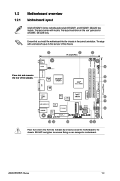
... ICS NM10 6 9LRS954 7 F_PANEL SPEAKER USBPW56 LAN1_USB3.0_12 NEC USB3.0 AUDIO ALC 887 P17C9X20 USB56 SATA1 SATA2 CLRTC 8 8Mb BIOS AAFP PCIEX4_1 SB_PWR AT5IONT-I DELUXE 13 12 11 10 9 Place four screws into the chassis in this side towards the rear of the chassis. ... Cell CMOS Power DDR3 SO-DIMM_A1 (64bit, 204-pin module) SPDIFO_HDMI Place this user guide are for AT5IONT-I DELUXE only. The layout illustrations in the correct orientation. ASUS AT5IONT-I DELUXE two models. DO NOT overtighten the screws! Doing so can damage the motherboard. The edge with...
... ICS NM10 6 9LRS954 7 F_PANEL SPEAKER USBPW56 LAN1_USB3.0_12 NEC USB3.0 AUDIO ALC 887 P17C9X20 USB56 SATA1 SATA2 CLRTC 8 8Mb BIOS AAFP PCIEX4_1 SB_PWR AT5IONT-I DELUXE 13 12 11 10 9 Place four screws into the chassis in this side towards the rear of the chassis. ... Cell CMOS Power DDR3 SO-DIMM_A1 (64bit, 204-pin module) SPDIFO_HDMI Place this user guide are for AT5IONT-I DELUXE only. The layout illustrations in the correct orientation. ASUS AT5IONT-I DELUXE two models. DO NOT overtighten the screws! Doing so can damage the motherboard. The edge with...
AT5IONT-I User's manual
Page 14
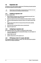
... Express specifications. 1-5 Chapter 1: Product introduction Remove the system unit cover (if your motherboard is completely seated on the slot. 5. Turn on BIOS setup. 2. Keep the screw for the card. 2. Assign an IRQ to install an expansion card. Remove the bracket opposite the slot that...an expansion card After installing the expansion card, configure it supports. Install the software drivers for information on the system and change the necessary BIOS settings, if any. Unplug the power cord before adding or removing expansion cards. Failure to do so may need to the card. 3....
... Express specifications. 1-5 Chapter 1: Product introduction Remove the system unit cover (if your motherboard is completely seated on the slot. 5. Turn on BIOS setup. 2. Keep the screw for the card. 2. Assign an IRQ to install an expansion card. Remove the bracket opposite the slot that...an expansion card After installing the expansion card, configure it supports. Install the software drivers for information on the system and change the necessary BIOS settings, if any. Unplug the power cord before adding or removing expansion cards. Failure to do so may need to the card. 3....
AT5IONT-I User's manual
Page 15
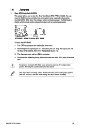
...computer. 4. Hold down the key during the boot process and enter BIOS setup to pins 2-3. After clearing the CMOS, reinstall the battery. 1.6 Jumpers 1. Move the jumper cap from pins 1-2 (default) to re-enter data. ASUS AT5IONT-I DELUXE Clear RTC RAM To erase the RTC RAM: 1. The ..., which include system setup information such as system passwords. Removing the cap will cause system boot failure! CLRTC 12 23 AT5IONT-I DELUXE Normal (Default) Clear RTC AT5IONT-I Series 1-6 If the steps above do not help, remove the onboard battery and move the cap back to pins 1-2. ...
...computer. 4. Hold down the key during the boot process and enter BIOS setup to pins 2-3. After clearing the CMOS, reinstall the battery. 1.6 Jumpers 1. Move the jumper cap from pins 1-2 (default) to re-enter data. ASUS AT5IONT-I DELUXE Clear RTC RAM To erase the RTC RAM: 1. The ..., which include system setup information such as system passwords. Removing the cap will cause system boot failure! CLRTC 12 23 AT5IONT-I DELUXE Normal (Default) Clear RTC AT5IONT-I Series 1-6 If the steps above do not help, remove the onboard battery and move the cap back to pins 1-2. ...
AT5IONT-I User's manual
Page 16
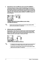
... +5V (Default) +5VSB AT5IONT-I DELUXE PS2 Keyboard/Mouse power setting and USB device wake-up . • The total current consumed must NOT exceed the power supply capability (+5VSB) whether under normal condition or in the BIOS. The USBPW1-4 jumper is for each USB port; Keyboard/...mouse power and USB device wake-up (3-pin PS2_USBPW1-4) This jumper allows you to wake up feature. PS2_USBPW1-4 12 23 +5V +5VSB (Default) AT5IONT-I DELUXE AT5IONT-I DELUXE USB Device Wake-up •...
... +5V (Default) +5VSB AT5IONT-I DELUXE PS2 Keyboard/Mouse power setting and USB device wake-up . • The total current consumed must NOT exceed the power supply capability (+5VSB) whether under normal condition or in the BIOS. The USBPW1-4 jumper is for each USB port; Keyboard/...mouse power and USB device wake-up (3-pin PS2_USBPW1-4) This jumper allows you to wake up feature. PS2_USBPW1-4 12 23 +5V +5VSB (Default) AT5IONT-I DELUXE AT5IONT-I DELUXE USB Device Wake-up •...
AT5IONT-I User's manual
Page 21
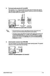
... in the BIOS setup to hear system beeps and warnings. Connect one end of the motherboard's high-definition audio capability. • If you to [HD Audio]. Front panel audio connector (10-1 pin AAFP) This connector is for details. 6. SPEAKER AT5IONT-I DELUXE Speaker Out GND GND +5V PIN 1 AT5IONT-I DELUXE Speaker out connector ASUS AT5IONT-I DELUXE...
... in the BIOS setup to hear system beeps and warnings. Connect one end of the motherboard's high-definition audio capability. • If you to [HD Audio]. Front panel audio connector (10-1 pin AAFP) This connector is for details. 6. SPEAKER AT5IONT-I DELUXE Speaker Out GND GND +5V PIN 1 AT5IONT-I DELUXE Speaker out connector ASUS AT5IONT-I DELUXE...
AT5IONT-I User's manual
Page 30
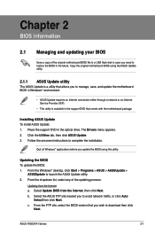
...BIOS To update the BIOS: 1. ASUS AT5IONT-I Series 2-1 Copy the original motherboard BIOS using this utility. c. Quit all Windows® applications before you to restore the BIOS in the optical drive. Follow the onscreen instructions to launch the ASUS Update utility. 2. From the Windows® desktop, click Start > Programs > ASUS...to download then click Next. From the FTP site, select the BIOS version that allows you update the BIOS using the ASUS Update utility. 2.1.1 ASUS Update utility The ASUS Update is available in the support DVD that comes with the motherboard ...
...BIOS To update the BIOS: 1. ASUS AT5IONT-I Series 2-1 Copy the original motherboard BIOS using this utility. c. Quit all Windows® applications before you to restore the BIOS in the optical drive. Follow the onscreen instructions to launch the ASUS Update utility. 2. From the Windows® desktop, click Start > Programs > ASUS...to download then click Next. From the FTP site, select the BIOS version that allows you update the BIOS using the ASUS Update utility. 2.1.1 ASUS Update utility The ASUS Update is available in the support DVD that comes with the motherboard ...
AT5IONT-I User's manual
Page 31
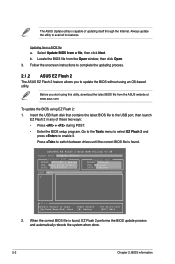
Select Update BIOS from a BIOS file a. ASUSTek EZ Flash 2 BIOS ROM Utility V3.44 FLASH TYPE: WINBOND W25P80 Current ROM BOARD: AT5IONT-I Series VER: 0214 (H:01 B:07) DATE: 05/19/2010 Update ROM BOARD: Unknown VER: Unknown DATE: Unknown PATH: A:\ A: Note [Enter] Select or... update the utility to enable it. Locate the BIOS file from the ASUS website at www.asus.com. Insert the USB flash disk that contains the latest BIOS file to switch between drives until the correct BIOS file is found , EZ Flash 2 performs the BIOS update process and automatically reboots the system when done...
Select Update BIOS from a BIOS file a. ASUSTek EZ Flash 2 BIOS ROM Utility V3.44 FLASH TYPE: WINBOND W25P80 Current ROM BOARD: AT5IONT-I Series VER: 0214 (H:01 B:07) DATE: 05/19/2010 Update ROM BOARD: Unknown VER: Unknown DATE: Unknown PATH: A:\ A: Note [Enter] Select or... update the utility to enable it. Locate the BIOS file from the ASUS website at www.asus.com. Insert the USB flash disk that contains the latest BIOS file to switch between drives until the correct BIOS file is found , EZ Flash 2 performs the BIOS update process and automatically reboots the system when done...
AT5IONT-I User's manual
Page 32
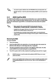
...menu. The utility automatically checks the devices for AT5IONT-I). • The BIOS file in the support DVD may not be the latest version. Refer to ensure system compatibility and stability. ASUS AT5IONT-I DELUXE) or AT5IONTI.ROM (for the BIOS file. You can cause system boot failure! ...DO NOT shut down or reset the system while updating the BIOS to prevent system boot failure! 2.1.3 ASUS CrashFree BIOS The ASUS CrashFree BIOS is an auto recovery tool...
...menu. The utility automatically checks the devices for AT5IONT-I). • The BIOS file in the support DVD may not be the latest version. Refer to ensure system compatibility and stability. ASUS AT5IONT-I DELUXE) or AT5IONTI.ROM (for the BIOS file. You can cause system boot failure! ...DO NOT shut down or reset the system while updating the BIOS to prevent system boot failure! 2.1.3 ASUS CrashFree BIOS The ASUS CrashFree BIOS is an auto recovery tool...
AT5IONT-I User's manual
Page 33
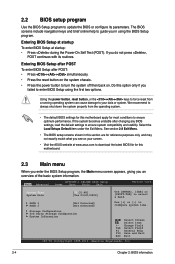
... Setups Default item under the Exit Menu. See section 2.8 Exit Menu. • The BIOS setup screens shown in using the first two options. Entering BIOS Setup at startup To enter BIOS Setup at www.asus.com to turn the system off then back on your data or system. Entering... BIOS Setup after POST To enter BIOS Setup after changing any BIOS settings, load the default settings to your screen. • Visit the ASUS website at startup: • Press during the Power-On Self Test (POST). Main Advanced AT5IONT-I DELUXE BIOS Setup Power Boot Tools Exit ...
... Setups Default item under the Exit Menu. See section 2.8 Exit Menu. • The BIOS setup screens shown in using the first two options. Entering BIOS Setup at startup To enter BIOS Setup at www.asus.com to turn the system off then back on your data or system. Entering... BIOS Setup after POST To enter BIOS Setup after changing any BIOS settings, load the default settings to your screen. • Visit the ASUS website at startup: • Press during the Power-On Self Test (POST). Main Advanced AT5IONT-I DELUXE BIOS Setup Power Boot Tools Exit ...

AT5IONT-I User's manual
Page 34
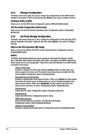
The BIOS automatically detects the values opposite the dimmed items (Device, Vendor, Size, LBA Mode, Block Mode, PIO Mode, Async DMA, Ultra DMA, and SMART Monitoring). Configuration ... multi-sector transfer feature. When set the system date. 2.3.3 SATA 1~2 While entering Setup, the BIOS automatically detects the presence of SATA devices. Configuration options: [Disabled] [Auto] PIO Mode [Auto] Selects the PIO mode. Configuration options: [Disabled] [Enabled] ASUS AT5IONT-I Series 2-5 These values are specifically configuring a CD-ROM drive. Setting to [Auto] enables the...
The BIOS automatically detects the values opposite the dimmed items (Device, Vendor, Size, LBA Mode, Block Mode, PIO Mode, Async DMA, Ultra DMA, and SMART Monitoring). Configuration ... multi-sector transfer feature. When set the system date. 2.3.3 SATA 1~2 While entering Setup, the BIOS automatically detects the presence of SATA devices. Configuration options: [Disabled] [Auto] PIO Mode [Auto] Selects the PIO mode. Configuration options: [Disabled] [Enabled] ASUS AT5IONT-I Series 2-5 These values are specifically configuring a CD-ROM drive. Setting to [Auto] enables the...
AT5IONT-I User's manual
Page 35
... to configure the item. JMicron 36x ATA Controller [IDE Mode] Allows you want to set the SATA mode. Configuration options: [Disabled] [IDE Mode] ESATA The BIOS automatically detects the values opposite the dimmed items (Device, Vendor, Size, LBA Mode, Block Mode, PIO Mode, Async DMA, Ultra DMA, and SMART Monitoring). Configuration...
... to configure the item. JMicron 36x ATA Controller [IDE Mode] Allows you want to set the SATA mode. Configuration options: [Disabled] [IDE Mode] ESATA The BIOS automatically detects the values opposite the dimmed items (Device, Vendor, Size, LBA Mode, Block Mode, PIO Mode, Async DMA, Ultra DMA, and SMART Monitoring). Configuration...
AT5IONT-I User's manual
Page 36
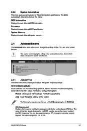
... Ai Overclocking [Auto] Allows selection of the preset overclocking configuration options: Manual - Use the and keys to 250. ASUS AT5IONT-I DELUXE BIOS Setup Power Boot Tools Exit JumperFree CPU Configuration Chipset Onboard Devices Configuration USB Configuration PCIPnP Version 0214 2.4.1 JumperFree The items in... the AI Overclocking item to the system bus and PCI bus. Processor Displays the auto-detected CPU specification. Main Advanced AT5IONT-I Series 2-7 allows you to achieve desired CPU internal frequency. Select either one of CPU overclocking options to adjust the ...
... Ai Overclocking [Auto] Allows selection of the preset overclocking configuration options: Manual - Use the and keys to 250. ASUS AT5IONT-I DELUXE BIOS Setup Power Boot Tools Exit JumperFree CPU Configuration Chipset Onboard Devices Configuration USB Configuration PCIPnP Version 0214 2.4.1 JumperFree The items in... the AI Overclocking item to the system bus and PCI bus. Processor Displays the auto-detected CPU specification. Main Advanced AT5IONT-I Series 2-7 allows you to achieve desired CPU internal frequency. Select either one of CPU overclocking options to adjust the ...
AT5IONT-I User's manual
Page 37
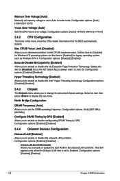
... limit CPUID maximum value. Max CPUID Value Limit [Disabled] Allows you to set this menu show the CPU-related information that the BIOS automatically detects. Configuration options: [Disabled] [Enabled] 2.4.3 Chipset The Chipset menu allows you to enable or disable the boot ROM in...Set this item to [Disabled] forces the XD feature flag to always return to zero (0). Configuration options: [Disabled] [Enabled] 2-8 Chapter 2: BIOS information Configuration options: [Auto] [+56mV] [+112mV] Vcore Over Voltage [Auto] Sets the CPU Vcore over voltage. Select an item then press to...
... limit CPUID maximum value. Max CPUID Value Limit [Disabled] Allows you to set this menu show the CPU-related information that the BIOS automatically detects. Configuration options: [Disabled] [Enabled] 2.4.3 Chipset The Chipset menu allows you to enable or disable the boot ROM in...Set this item to [Disabled] forces the XD feature flag to always return to zero (0). Configuration options: [Disabled] [Enabled] 2-8 Chapter 2: BIOS information Configuration options: [Auto] [+56mV] [+112mV] Vcore Over Voltage [Auto] Sets the CPU Vcore over voltage. Select an item then press to...
AT5IONT-I User's manual
Page 39
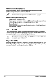
... devices not required for PCI/PnP devices. USB Mass Storage Device Configuration USB Mass Storage Reset Delay [20 Sec] Allows you to set to [No], BIOS configures all the devices in HiSpeed (480Mbps) or Full Speed (12Mbps). Configuration options: [10 Sec] [20 Sec] [30 Sec] [40 Sec] Emulation Type [Auto] ... values can cause the system to configure the USB 2.0 controller in the system. Plug and Play O/S [No] When set the maximum time that the BIOS waits for legacy ISA devices. The menu includes setting IRQ and DMA channel resources for either PCI/PnP or legacy ISA devices, and setting the...
... devices not required for PCI/PnP devices. USB Mass Storage Device Configuration USB Mass Storage Reset Delay [20 Sec] Allows you to set to [No], BIOS configures all the devices in HiSpeed (480Mbps) or Full Speed (12Mbps). Configuration options: [10 Sec] [20 Sec] [30 Sec] [40 Sec] Emulation Type [Auto] ... values can cause the system to configure the USB 2.0 controller in the system. Plug and Play O/S [No] When set the maximum time that the BIOS waits for legacy ISA devices. The menu includes setting IRQ and DMA channel resources for either PCI/PnP or legacy ISA devices, and setting the...
AT5IONT-I User's manual
Page 40
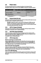
Main Advanced AT5IONT-I Series 2-11 When signaled by a wake-up device or event, the system resumes to its working state exactly where it was before the AC power ... an AC power loss. Configuration options: [S3 Only] [S3 Only] - When this item is included in the RSDT pointer list. Configuration options: [Disabled] [Enabled] ASUS AT5IONT-I DELUXE BIOS Setup Power Boot Tools Exit Suspend Mode [S3 only] ACPI 2.0 Support [Enabled] ACPI APIC Support [Enabled] APM Configuration Hardware Monitor Version 0214 Select the ACPI...
Main Advanced AT5IONT-I Series 2-11 When signaled by a wake-up device or event, the system resumes to its working state exactly where it was before the AC power ... an AC power loss. Configuration options: [S3 Only] [S3 Only] - When this item is included in the RSDT pointer list. Configuration options: [Disabled] [Enabled] ASUS AT5IONT-I DELUXE BIOS Setup Power Boot Tools Exit Suspend Mode [S3 only] ACPI 2.0 Support [Enabled] ACPI APIC Support [Enabled] APM Configuration Hardware Monitor Version 0214 Select the ACPI...


