User Manual
Page 8
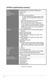
... more, Windows® 32-bit operating system may only recognize less than 3GB. AT3N7A-I specifications summary CPU Chipset Front Side Bus Memory Graphics Expansion slot Storage Audio LAN USB Fan rated speed ASUS special features Integrated Dual-Core Intel® Atom™ 330 processor NVIDIA® ...ION™ 533 MHz Dual channel memory architecture - 2 x 240-pin DIMM sockets support maximum 4GB unbuffered non-ECC 800/667 MHz DDR2 memory modules * Refer to www.asus.com or this user manual for the Memory QVL (Qualified Vendors Lists). ** When you install ...
... more, Windows® 32-bit operating system may only recognize less than 3GB. AT3N7A-I specifications summary CPU Chipset Front Side Bus Memory Graphics Expansion slot Storage Audio LAN USB Fan rated speed ASUS special features Integrated Dual-Core Intel® Atom™ 330 processor NVIDIA® ...ION™ 533 MHz Dual channel memory architecture - 2 x 240-pin DIMM sockets support maximum 4GB unbuffered non-ECC 800/667 MHz DDR2 memory modules * Refer to www.asus.com or this user manual for the Memory QVL (Qualified Vendors Lists). ** When you install ...
User Manual
Page 9
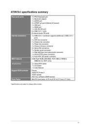
AT3N7A-I specifications summary Rear panel ports Internal connectors BIOS features Accessories Support DVD contents Form Factor 1 x PS/2 Keyboard port 1 x Bluetooth adapter 1 x eSATA port 2 x S/PDIF out ports (... 1 x High definition front panel audio connector 1 x 24-pin EATX power connector 1 x 4-pin ATX 12V power connector 8 Mb Flash ROM, AMI BIOS, PnP, DMI2.0, WfM2.0, SMBIOS 2.5, ACPI v2.0a 2 x Serial ATA cables 1 x I/O shield 1 x User Manual Drivers ASUS PC Probe II ASUS Update Anti-virus software (OEM version) Mini ITX form factor: 6.75 in x 6.75 in (17.1cm...
AT3N7A-I specifications summary Rear panel ports Internal connectors BIOS features Accessories Support DVD contents Form Factor 1 x PS/2 Keyboard port 1 x Bluetooth adapter 1 x eSATA port 2 x S/PDIF out ports (... 1 x High definition front panel audio connector 1 x 24-pin EATX power connector 1 x 4-pin ATX 12V power connector 8 Mb Flash ROM, AMI BIOS, PnP, DMI2.0, WfM2.0, SMBIOS 2.5, ACPI v2.0a 2 x Serial ATA cables 1 x I/O shield 1 x User Manual Drivers ASUS PC Probe II ASUS Update Anti-virus software (OEM version) Mini ITX form factor: 6.75 in x 6.75 in (17.1cm...
User Manual
Page 11
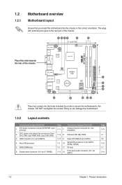
... DIMM slots 6. CPU, power, and chassis fan connectors (3-pin CPU_FAN, 3-pin PWR_FAN, 3-pin CHA_FAN) 3. Serial ATA connectors (7-pin SATA1, SATA2, SATA3) 1-3 11. System panel connector (10-1 pin F_PANEL) Page 1-11 7. The edge with external ports goes to the chassis. 1.2 1.2.1 Motherboard overview Motherboard layout Ensure that you install the motherboard into the holes indicated by circles to secure the...
... DIMM slots 6. CPU, power, and chassis fan connectors (3-pin CPU_FAN, 3-pin PWR_FAN, 3-pin CHA_FAN) 3. Serial ATA connectors (7-pin SATA1, SATA2, SATA3) 1-3 11. System panel connector (10-1 pin F_PANEL) Page 1-11 7. The edge with external ports goes to the chassis. 1.2 1.2.1 Motherboard overview Motherboard layout Ensure that you install the motherboard into the holes indicated by circles to secure the...
User Manual
Page 17
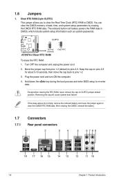
... the cap will cause system boot failure! The onboard button cell battery powers the RAM data in CMOS. Move the jumper cap from pins 1-2 (default) to re-enter data. Plug the power cord and turn ON the computer. 4. 1.6 Jumpers 1. After clearing the CMOS, reinstall the battery. 1.7 ...Connectors 1.7.1 Rear panel connectors 1-8 Chapter 1: Product introduction Except when clearing the RTC RAM, never remove the cap on pins 2-3 for about 5-10 seconds, then move the jumper again to clear the CMOS RTC RAM data. Turn OFF the computer and unplug the power cord...
... the cap will cause system boot failure! The onboard button cell battery powers the RAM data in CMOS. Move the jumper cap from pins 1-2 (default) to re-enter data. Plug the power cord and turn ON the computer. 4. 1.6 Jumpers 1. After clearing the CMOS, reinstall the battery. 1.7 ...Connectors 1.7.1 Rear panel connectors 1-8 Chapter 1: Product introduction Except when clearing the RTC RAM, never remove the cap on pins 2-3 for about 5-10 seconds, then move the jumper again to clear the CMOS RTC RAM data. Turn OFF the computer and unplug the power cord...
User Manual
Page 18
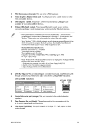
... RAM; 5V single supply voltage. • Under Windows® XP, if the Bluetooth Driver item is for the LAN port LED indications. ASUS AT3N7A-I 1-9 Transmission rate up your computer. 3. Working distance up to a Local Area Network (LAN) through a network hub. This port connects ... connection and data transfer between your computer and switch off the Power Supply Unit (PSU). 2. USB 2.0 ports 5 and 6. These two 4-pin Universal Serial Bus (USB) ports are available for a VGA monitor or other audio sources. Onboard Bluetooth module. Video Graphics Adapter (VGA) port...
... RAM; 5V single supply voltage. • Under Windows® XP, if the Bluetooth Driver item is for the LAN port LED indications. ASUS AT3N7A-I 1-9 Transmission rate up your computer. 3. Working distance up to a Local Area Network (LAN) through a network hub. This port connects ... connection and data transfer between your computer and switch off the Power Supply Unit (PSU). 2. USB 2.0 ports 5 and 6. These two 4-pin Universal Serial Bus (USB) ports are available for a VGA monitor or other audio sources. Onboard Bluetooth module. Video Graphics Adapter (VGA) port...
User Manual
Page 19
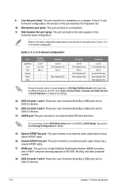
...port becomes Front Speaker Out. 10. To use hot-plug, set the SATA Mode Select item in the 8-channel audio configuration. 9. These two 4-pin Universal Serial Bus (USB) ports are for a High-Definition Multimedia Interface (HDMI) connector, and is for USB 2.0 devices. 14. This port ...connects to a headphone or a speaker. This port connects to an external audio output device via an optical S/PDIF cable. 16. These two 4-pin Universal Serial Bus (USB) ports are for USB 2.0 devices. 1-10 Chapter 1: Product introduction Coaxial S/PDIF Out port. This port is HDCP compliant...
...port becomes Front Speaker Out. 10. To use hot-plug, set the SATA Mode Select item in the 8-channel audio configuration. 9. These two 4-pin Universal Serial Bus (USB) ports are for a High-Definition Multimedia Interface (HDMI) connector, and is for USB 2.0 devices. 14. This port ...connects to a headphone or a speaker. This port connects to an external audio output device via an optical S/PDIF cable. 16. These two 4-pin Universal Serial Bus (USB) ports are for USB 2.0 devices. 1-10 Chapter 1: Product introduction Coaxial S/PDIF Out port. This port is HDCP compliant...
User Manual
Page 20
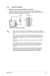
... can provide at least 15 A on +12 V and that you are uncertain about the minimum power supply requirement for your system, refer to connect the 4-pin ATX +12V power plug. 1.7.2 Internal connectors 1. Find the proper orientation and push down firmly until the connectors completely fit. • We recommend that the PSU... unstable or may not boot up if the power is inadequate. • DO NOT forget to the Recommended Power Supply Wattage Calculator at http://support.asus. The power supply plugs are for details. ASUS AT3N7A-I 1-11
... can provide at least 15 A on +12 V and that you are uncertain about the minimum power supply requirement for your system, refer to connect the 4-pin ATX +12V power plug. 1.7.2 Internal connectors 1. Find the proper orientation and push down firmly until the connectors completely fit. • We recommend that the PSU... unstable or may not boot up if the power is inadequate. • DO NOT forget to the Recommended Power Supply Wattage Calculator at http://support.asus. The power supply plugs are for details. ASUS AT3N7A-I 1-11
User Manual
Page 21
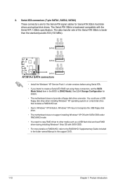
2. Serial ATA connectors (7-pin SATA1, SATA2, SATA3) These connectors are for the Serial ATA signal cables for details. • The motherboard does not provide a floppy disk drive connector. The data transfer rate of the Serial ATA 3Gb/s is backward compatible with SATA ODD. • For more ...set using these connectors, set . • Due to Windows® XP limitation, Windows® XP may not recognize the USB floppy disk drive. • The motherboard does not support installing Windows® XP OS with SATA ODD under RAID/AHCI mode. • You need to copy RAID driver to the RAID...
2. Serial ATA connectors (7-pin SATA1, SATA2, SATA3) These connectors are for the Serial ATA signal cables for details. • The motherboard does not provide a floppy disk drive connector. The data transfer rate of the Serial ATA 3Gb/s is backward compatible with SATA ODD. • For more ...set using these connectors, set . • Due to Windows® XP limitation, Windows® XP may not recognize the USB floppy disk drive. • The motherboard does not support installing Windows® XP OS with SATA ODD under RAID/AHCI mode. • You need to copy RAID driver to the RAID...
User Manual
Page 22
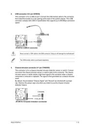
...the system chassis. The signal is purchased separately. 4. Remove the jumper caps only when you intend to this connector. By default, the pin labeled "Chassis Signal" and "Ground" are shorted with USB 2.0 specification that supports up to a slot opening at the back of ...10-1 pin USB910) This connector is for a USB 2.0 port. Never connect a 1394 cable to this connector, then install the module to 480 Mbps connection speed. The chassis intrusion sensor or switch sends a high-level signal to the USB connector. ASUS AT3N7A-I 1-13 Doing so will damage the motherboard! ...
...the system chassis. The signal is purchased separately. 4. Remove the jumper caps only when you intend to this connector. By default, the pin labeled "Chassis Signal" and "Ground" are shorted with USB 2.0 specification that supports up to a slot opening at the back of ...10-1 pin USB910) This connector is for a USB 2.0 port. Never connect a 1394 cable to this connector, then install the module to 480 Mbps connection speed. The chassis intrusion sensor or switch sends a high-level signal to the USB connector. ASUS AT3N7A-I 1-13 Doing so will damage the motherboard! ...
User Manual
Page 23
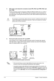
CPU, power, and chassis fan connectors (3-pin CPU_FAN, 3-pin PWR_FAN, 3-pin CHA_FAN) The fan connectors support cooling fans of 350 mA~2000 mA (24 W max.) or a total of the motherboard's high-definition audio capability. • If you want to connect a high-definition front panel audio module to this ...+12V. Connect the fan cables to [AC97]. Do not place jumper caps on the motherboard, ensuring that supports either HD Audio or legacy AC`97 audio standard. Front panel audio connector (10-1 pin AAFP) This connector is set the item to the fan connectors on the fan connectors! ...
CPU, power, and chassis fan connectors (3-pin CPU_FAN, 3-pin PWR_FAN, 3-pin CHA_FAN) The fan connectors support cooling fans of 350 mA~2000 mA (24 W max.) or a total of the motherboard's high-definition audio capability. • If you want to connect a high-definition front panel audio module to this ...+12V. Connect the fan cables to [AC97]. Do not place jumper caps on the motherboard, ensuring that supports either HD Audio or legacy AC`97 audio standard. Front panel audio connector (10-1 pin AAFP) This connector is set the item to the fan connectors on the fan connectors! ...
User Manual
Page 24
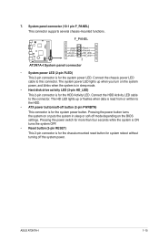
... Activity LED cable to this connector. ASUS AT3N7A-I 1-15 The system power LED lights up or flashes when data is read from or written to this connector. Connect the chassis power LED cable to the HDD. • ATX power button/soft-off button (2-pin PWRBTN) This connector is for the.... 7. Pressing the power switch for more than four seconds while the system is ON turns the system OFF. • Reset button (2-pin RESET) This 2-pin connector is for system reboot without turning off mode depending on or puts the system in sleep mode. • Hard disk drive activity ...
... Activity LED cable to this connector. ASUS AT3N7A-I 1-15 The system power LED lights up or flashes when data is read from or written to this connector. Connect the chassis power LED cable to the HDD. • ATX power button/soft-off button (2-pin PWRBTN) This connector is for the.... 7. Pressing the power switch for more than four seconds while the system is ON turns the system OFF. • Reset button (2-pin RESET) This 2-pin connector is for system reboot without turning off mode depending on or puts the system in sleep mode. • Hard disk drive activity ...


