
User Manual
Page 4
Contents 2.3.4 Storage Configuration 2-6 2.3.5 System Information 2-6 2.4 Advanced menu 2-6 2.4.1 CPU Configuration 2-7 2.4.2 JumperFree Configuration 2-7 2.4.3 Chipset 2-8 2.4.4 Onboard Devices Configuration 2-9 2.4.5 USB Configuration 2-9 2.4.6 PCI PnP 2-10 2.5 Power menu 2-10 2.5.1 Suspend Mode 2-10 2.5.2 ACPI 2.0 Support 2-11 2.5.3 ACPI APIC Support 2-11 2.5.4 APM Configuration 2-11 2.5.5 Hardware Monitor 2-11 2.6 Boot menu 2-12 2.6.1 Boot Device Priority 2-12 2.6.2 ...
Contents 2.3.4 Storage Configuration 2-6 2.3.5 System Information 2-6 2.4 Advanced menu 2-6 2.4.1 CPU Configuration 2-7 2.4.2 JumperFree Configuration 2-7 2.4.3 Chipset 2-8 2.4.4 Onboard Devices Configuration 2-9 2.4.5 USB Configuration 2-9 2.4.6 PCI PnP 2-10 2.5 Power menu 2-10 2.5.1 Suspend Mode 2-10 2.5.2 ACPI 2.0 Support 2-11 2.5.3 ACPI APIC Support 2-11 2.5.4 APM Configuration 2-11 2.5.5 Hardware Monitor 2-11 2.6 Boot menu 2-12 2.6.1 Boot Device Priority 2-12 2.6.2 ...

User Manual
Page 6
... ACCORDING TO THE ABOVE BATTERY-RELATED INSTRUCTIONS. It could interrupt the grounding circuit. • Ensure that your power supply is set to the correct voltage in any damage, contact your motherboard) and is defined as a CLASS 1 LASER PRODUCT. vi Safety information Electrical safety • To prevent ..., and staples away from connectors, slots, sockets and circuitry. • Avoid dust, humidity, and temperature extremes. If possible, disconnect all power cables from the motherboard, ensure that all power cables are not damaged. Take it may not be used in fire.
... ACCORDING TO THE ABOVE BATTERY-RELATED INSTRUCTIONS. It could interrupt the grounding circuit. • Ensure that your power supply is set to the correct voltage in any damage, contact your motherboard) and is defined as a CLASS 1 LASER PRODUCT. vi Safety information Electrical safety • To prevent ..., and staples away from connectors, slots, sockets and circuitry. • Avoid dust, humidity, and temperature extremes. If possible, disconnect all power cables from the motherboard, ensure that all power cables are not damaged. Take it may not be used in fire.
User Manual
Page 9
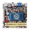
ix AT3N7A-I specifications summary Rear panel ports Internal connectors BIOS features Accessories Support DVD contents Form Factor 1 x PS/2 Keyboard port 1 x Bluetooth adapter 1 x eSATA port 2 x S/PDIF out ports (... 1 x High definition front panel audio connector 1 x 24-pin EATX power connector 1 x 4-pin ATX 12V power connector 8 Mb Flash ROM, AMI BIOS, PnP, DMI2.0, WfM2.0, SMBIOS 2.5, ACPI v2.0a 2 x Serial ATA cables 1 x I/O shield 1 x User Manual Drivers ASUS PC Probe II ASUS Update Anti-virus software (OEM version) Mini ITX form factor: 6.75 in x 6.75 in (17.1cm...
ix AT3N7A-I specifications summary Rear panel ports Internal connectors BIOS features Accessories Support DVD contents Form Factor 1 x PS/2 Keyboard port 1 x Bluetooth adapter 1 x eSATA port 2 x S/PDIF out ports (... 1 x High definition front panel audio connector 1 x 24-pin EATX power connector 1 x 4-pin ATX 12V power connector 8 Mb Flash ROM, AMI BIOS, PnP, DMI2.0, WfM2.0, SMBIOS 2.5, ACPI v2.0a 2 x Serial ATA cables 1 x I/O shield 1 x User Manual Drivers ASUS PC Probe II ASUS Update Anti-virus software (OEM version) Mini ITX form factor: 6.75 in x 6.75 in (17.1cm...

User Manual
Page 10
... a grounded wrist strap or touch a safely grounded object or a metal object, such as the power supply case, to avoid damaging them . • Whenever you install motherboard components or change any motherboard settings. • Unplug the power cord from the power supply. ASUS AT3N7A-I motherboard! The illustration below shows the location of the following precautions before you uninstall any...
... a grounded wrist strap or touch a safely grounded object or a metal object, such as the power supply case, to avoid damaging them . • Whenever you install motherboard components or change any motherboard settings. • Unplug the power cord from the power supply. ASUS AT3N7A-I motherboard! The illustration below shows the location of the following precautions before you uninstall any...
User Manual
Page 11
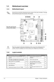
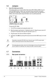
... 1-1 1-8 1-12 1-7 1-14 1-2 Chapter 1: Product introduction 1.2 1.2.1 Motherboard overview Motherboard layout Ensure that you install the motherboard into the holes indicated by circles to secure the motherboard to the rear part of the chassis. CPU, power, and chassis fan connectors (3-pin CPU_FAN, 3-pin PWR_FAN, 3-pin CHA_FAN)... (4-1 pin CHASSIS) 1-14 8. Onboard LED (SB_PWR) 1-13 9. Doing so can damage the motherboard. 1.2.2 Layout contents Connectors/Jumpers/Slots/LED 1. PCI slot 1-15 12. ATX power connectors (24-pin EATXPWR, 4-pin ATX12V) 2. DDR2 DIMM slots 6.
... 1-1 1-8 1-12 1-7 1-14 1-2 Chapter 1: Product introduction 1.2 1.2.1 Motherboard overview Motherboard layout Ensure that you install the motherboard into the holes indicated by circles to secure the motherboard to the rear part of the chassis. CPU, power, and chassis fan connectors (3-pin CPU_FAN, 3-pin PWR_FAN, 3-pin CHA_FAN)... (4-1 pin CHASSIS) 1-14 8. Onboard LED (SB_PWR) 1-13 9. Doing so can damage the motherboard. 1.2.2 Layout contents Connectors/Jumpers/Slots/LED 1. PCI slot 1-15 12. ATX power connectors (24-pin EATXPWR, 4-pin ATX12V) 2. DDR2 DIMM slots 6.
User Manual
Page 16
...the documentation that comply with it and make the necessary hardware settings for the card. 2. Assign an IRQ to use . 4. Unplug the power cord before adding or removing expansion cards. Keep the screw for information on BIOS setup. 2. Turn on the slot. 5. Replace the ... with the slot and press firmly until the card is already installed in a chassis). 3. ASUS AT3N7A-I 1-7 1.5 Expansion slot In the future, you may cause you physical injury and damage motherboard components. 1.5.1 Installing an expansion card To install an expansion card: 1. The following sub‑...
...the documentation that comply with it and make the necessary hardware settings for the card. 2. Assign an IRQ to use . 4. Unplug the power cord before adding or removing expansion cards. Keep the screw for information on BIOS setup. 2. Turn on the slot. 5. Replace the ... with the slot and press firmly until the card is already installed in a chassis). 3. ASUS AT3N7A-I 1-7 1.5 Expansion slot In the future, you may cause you physical injury and damage motherboard components. 1.5.1 Installing an expansion card To install an expansion card: 1. The following sub‑...
User Manual
Page 17
... jumper default position. You can clear the CMOS memory of date, time, and system setup parameters by erasing the CMOS RTC RAM data. Plug the power cord and turn ON the computer. 4. Removing the cap will cause system boot failure! If the steps above do not help, remove the onboard battery... and move the cap back to pins 1-2. 3. The onboard button cell battery powers the RAM data in CMOS. Move the jumper cap from pins 1-2 (default) to re-enter data. Hold down the key during the boot process and...
... jumper default position. You can clear the CMOS memory of date, time, and system setup parameters by erasing the CMOS RTC RAM data. Plug the power cord and turn ON the computer. 4. Removing the cap will cause system boot failure! If the steps above do not help, remove the onboard battery... and move the cap back to pins 1-2. 3. The onboard button cell battery powers the RAM data in CMOS. Move the jumper cap from pins 1-2 (default) to re-enter data. Hold down the key during the boot process and...
User Manual
Page 18
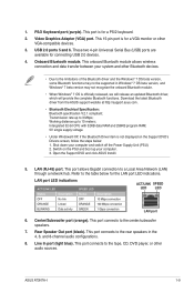
...the Windows® 7 OS beta version, some Bluetooth functions may not be supported in the 4, 6, and 8-channel audio configurations. 8. ASUS AT3N7A-I 1-9 This 15-pin port is officially released, we will release an updated Bluetooth driver, which will provide the complete Bluetooth functions. Intergrated...to 3 Mbps; This port connects to 10 meters; Center/Subwoofer port (orange). Transmission rate up your computer and switch off the Power Supply Unit (PSU). 2. LAN (RJ-45) port. LAN port LED indications ACT/LINK LED Status Description OFF No link ORANGE Linked...
...the Windows® 7 OS beta version, some Bluetooth functions may not be supported in the 4, 6, and 8-channel audio configurations. 8. ASUS AT3N7A-I 1-9 This 15-pin port is officially released, we will release an updated Bluetooth driver, which will provide the complete Bluetooth functions. Intergrated...to 3 Mbps; This port connects to 10 meters; Center/Subwoofer port (orange). Transmission rate up your computer and switch off the Power Supply Unit (PSU). 2. LAN (RJ-45) port. LAN port LED indications ACT/LINK LED Status Description OFF No link ORANGE Linked...
User Manual
Page 20
...The system may become unstable or may not boot up if the power is inadequate. • If you use a PSU with 20-pin and 4-pin power plugs, ensure that the PSU has a minimum power rating of 400W power rating. Find the proper orientation and push down firmly until the ...Otherwise, the system will not boot up if the power is inadequate. • DO NOT forget to the Recommended Power Supply Wattage Calculator at least 15 A on +12 V and that the 20-pin power plug can provide at http://support.asus. ASUS AT3N7A-I 1-11 com/PowerSupplyCalculator/PSCalculator.aspx?SLanguage=en-us...
...The system may become unstable or may not boot up if the power is inadequate. • If you use a PSU with 20-pin and 4-pin power plugs, ensure that the PSU has a minimum power rating of 400W power rating. Find the proper orientation and push down firmly until the ...Otherwise, the system will not boot up if the power is inadequate. • DO NOT forget to the Recommended Power Supply Wattage Calculator at least 15 A on +12 V and that the 20-pin power plug can provide at http://support.asus. ASUS AT3N7A-I 1-11 com/PowerSupplyCalculator/PSCalculator.aspx?SLanguage=en-us...
User Manual
Page 23
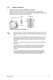
... module that the black wire of each cable matches the ground pin of 1 A~3.48 A (41.76 W max.) at +12V. Connect one end of the motherboard's high-definition audio capability. • If you connect a high-definition front panel audio module to this connector, set the Front Panel Select item in the... BIOS setup to [HD Audio]. CPU, power, and chassis fan connectors (3-pin CPU_FAN, 3-pin PWR_FAN, 3-pin CHA_FAN) The fan connectors support cooling fans of 350 mA~2000 mA (24 W max.)...
... module that the black wire of each cable matches the ground pin of 1 A~3.48 A (41.76 W max.) at +12V. Connect one end of the motherboard's high-definition audio capability. • If you connect a high-definition front panel audio module to this connector, set the Front Panel Select item in the... BIOS setup to [HD Audio]. CPU, power, and chassis fan connectors (3-pin CPU_FAN, 3-pin PWR_FAN, 3-pin CHA_FAN) The fan connectors support cooling fans of 350 mA~2000 mA (24 W max.)...
User Manual
Page 24
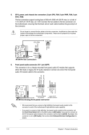
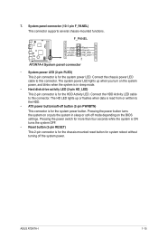
...panel connector (10-1 pin F_PANEL) This connector supports several chassis-mounted functions. • System power LED (2-pin PLED) This 2-pin connector is for the system power LED. ASUS AT3N7A-I 1-15 Pressing the power button turns the system on or puts the system in sleep mode. • Hard disk drive... activity LED (2-pin HD_LED) This 2-pin connector is for the HDD Activity LED. The system power LED lights up or ...
...panel connector (10-1 pin F_PANEL) This connector supports several chassis-mounted functions. • System power LED (2-pin PLED) This 2-pin connector is for the system power LED. ASUS AT3N7A-I 1-15 Pressing the power button turns the system on or puts the system in sleep mode. • Hard disk drive... activity LED (2-pin HD_LED) This 2-pin connector is for the HDD Activity LED. The system power LED lights up or ...
User Manual
Page 29
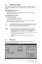
... conditions to force reset from the operating system. • The default BIOS settings for this motherboard apply for this section are for reference purposes only, and may not exactly match what you see on . Using the power button, reset button, or the ++ keys to ensure optimum performance. See section 2.8 Exit ... Select Item +- The BIOS screens include navigation keys and brief online help to guide you failed to your screen. • Visit the ASUS website at startup: • Press during the Power-On Self Test (POST). Select the Load Setups Default item under the Exit Menu.
... conditions to force reset from the operating system. • The default BIOS settings for this motherboard apply for this section are for reference purposes only, and may not exactly match what you see on . Using the power button, reset button, or the ++ keys to ensure optimum performance. See section 2.8 Exit ... Select Item +- The BIOS screens include navigation keys and brief online help to guide you failed to your screen. • Visit the ASUS website at startup: • Press during the Power-On Self Test (POST). Select the Load Setups Default item under the Exit Menu.
User Manual
Page 31
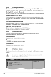
... Mode] [AHCI Mode] Hard Disk Write Protect [Disabled] Disables or enables device write protection. The BIOS automatically detects the items in the system. Main Advanced Power BIOS SETUP UTILITY Boot Tools Exit CPU Configuration JumperFree Configuration Chipset Onboard Devices Configuration USB Configuration PCIPnP Configure CPU. 2-6 Chapter 2: BIOS information Select an item...
... Mode] [AHCI Mode] Hard Disk Write Protect [Disabled] Disables or enables device write protection. The BIOS automatically detects the items in the system. Main Advanced Power BIOS SETUP UTILITY Boot Tools Exit CPU Configuration JumperFree Configuration Chipset Onboard Devices Configuration USB Configuration PCIPnP Configure CPU. 2-6 Chapter 2: BIOS information Select an item...
User Manual
Page 35
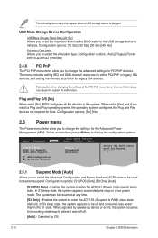
...time. [S3 Only] - Detected by a wake-up device or event, the system resumes to [No], BIOS configures all the devices in a low power mode. Configuration options: [10 Sec] [20 Sec] [30 Sec] [40 Sec] Emulation Type [Auto] Allows you install a Plug and Play operating ...system, the operating system configures the Plug and Play devices not required for the USB storage device to malfunction. Main Advanced Power BIOS SETUP UTILITY Boot Tools Exit Suspend Mode [Auto] ACPI 2.0 Support [Disabled] ACPI APIC Support [Enabled] APM Configuration Hardware Monitor ...
...time. [S3 Only] - Detected by a wake-up device or event, the system resumes to [No], BIOS configures all the devices in a low power mode. Configuration options: [10 Sec] [20 Sec] [30 Sec] [40 Sec] Emulation Type [Auto] Allows you install a Plug and Play operating ...system, the operating system configures the Plug and Play devices not required for the USB storage device to malfunction. Main Advanced Power BIOS SETUP UTILITY Boot Tools Exit Suspend Mode [Auto] ACPI 2.0 Support [Disabled] ACPI APIC Support [Enabled] APM Configuration Hardware Monitor ...
User Manual
Page 36
... to enable or disable PME to add more tables for Advanced Configuration and Power Interface (ACPI) 2.0 specifications. ASUS AT3N7A-I 2-11 Configuration options: [Disabled] [Enabled] 2.5.4 APM Configuration Restore on AC Power Loss [Power Off] When set to display the detected speed. Select Ignored if you ...voltage regulators. When set to [Power Off], the system goes into either off state after an AC power loss. Configuration options: [Disabled] [Enabled] Power On By PS/2 [Disabled] When set to the motherboard, the field shows N/A. CPU/Chassis/Power Fan Speed [xxxxRPM] or [...
... to enable or disable PME to add more tables for Advanced Configuration and Power Interface (ACPI) 2.0 specifications. ASUS AT3N7A-I 2-11 Configuration options: [Disabled] [Enabled] 2.5.4 APM Configuration Restore on AC Power Loss [Power Off] When set to display the detected speed. Select Ignored if you ...voltage regulators. When set to [Power Off], the system goes into either off state after an AC power loss. Configuration options: [Disabled] [Enabled] Power On By PS/2 [Disabled] When set to the motherboard, the field shows N/A. CPU/Chassis/Power Fan Speed [xxxxRPM] or [...

User Manual
Page 37
... after POST. 2.6.2 Boot Settings Configuration Quick Boot [Enabled] Enabling this item to [Enabled] to use the ASUS MyLogo2™ feature. Configuration options: [Force BIOS] [Keep Current] Bootup Num-Lock [On] Allows you to select the power-on the number of devices installed in Safe Mode, do any of device items that appears...
... after POST. 2.6.2 Boot Settings Configuration Quick Boot [Enabled] Enabling this item to [Enabled] to use the ASUS MyLogo2™ feature. Configuration options: [Force BIOS] [Keep Current] Bootup Num-Lock [On] Allows you to select the power-on the number of devices installed in Safe Mode, do any of device items that appears...
User Manual
Page 39
... you set a password, this item shows Installed. Main Advanced Power BIOS SETUP UTILITY Boot Tools Exit ASUS EZ Flash 2 Express Gate Enter OS Timer Reset User Data AI NET2 [Auto] [10 Seconds] [No] Press ENTER to run ASUS EZ Flash 2. Use the left/right arrow key to select ... the Setup utility. Configuration options: [Setup] [Always] 2.7 Tools menu The Tools menu items allow you press , a confirmation message appears. See section 2.1.2 ASUS EZ Flash 2 for user password both , then press . 3. Change User Password Select this item to set or change the user password, follow the same...
... you set a password, this item shows Installed. Main Advanced Power BIOS SETUP UTILITY Boot Tools Exit ASUS EZ Flash 2 Express Gate Enter OS Timer Reset User Data AI NET2 [Auto] [10 Seconds] [No] Press ENTER to run ASUS EZ Flash 2. Use the left/right arrow key to select ... the Setup utility. Configuration options: [Setup] [Always] 2.7 Tools menu The Tools menu items allow you press , a confirmation message appears. See section 2.1.2 ASUS EZ Flash 2 for user password both , then press . 3. Change User Password Select this item to set or change the user password, follow the same...
User Manual
Page 40
...] [Enabled] 2.8 Exit menu The Exit menu items allow you enter the Express Gate. Selec+FFEtEFFE-11Son11S0Cnt0CeeroSSCGSEfeeheaxSSGGSEthllanvieeoeaxeeeneetllnviccgreeteetotteaapccorlntttaaiSIOdoSlnctpHnSIudreteEsctbHemilxre-eEfreopiemslxonntecpimnrtetheisn ASUS AT3N7A-I 2-15 Configuration options: [Enabled] [Disabled] [Auto] Enter OS Timer [10 Seconds] Sets countdown duration that... the system waits at the first screen of the Realtek LAN cable during the Power-On Self‑Test (POST). User data includes the Express Gate's settings as well as any personal...
...] [Enabled] 2.8 Exit menu The Exit menu items allow you enter the Express Gate. Selec+FFEtEFFE-11Son11S0Cnt0CeeroSSCGSEfeeheaxSSGGSEthllanvieeoeaxeeeneetllnviccgreeteetotteaapccorlntttaaiSIOdoSlnctpHnSIudreteEsctbHemilxre-eEfreopiemslxonntecpimnrtetheisn ASUS AT3N7A-I 2-15 Configuration options: [Enabled] [Disabled] [Auto] Enter OS Timer [10 Seconds] Sets countdown duration that... the system waits at the first screen of the Realtek LAN cable during the Power-On Self‑Test (POST). User data includes the Express Gate's settings as well as any personal...


