
User Manual
Page 3
... 1-2 1.2.1 Motherboard layout 1-2 1.2.2 Layout contents 1-2 1.3 Central Processing Unit (CPU 1-3 1.4 System memory 1-3 1.4.1 Overview 1-3 1.4.2 Memory configurations 1-3 1.5 Expansion slots 1-4 1.5.1 Installing an expansion card 1-4 1.5.2 Configuring an expansion card 1-4 1.5.3 PCI slot 1-4 1.6 Jumpers 1-5 1.7 Connectors 1-7 1.7.1 Rear panel ports 1-7 1.7.2 Internal connectors 1-8 1.8 Software support 1-14 1.8.1 Installing an operating system 1-14 1.8.2 Support DVD information 1-14 Chapter 2: BIOS information 2.1 Managing and updating your BIOS 2-1 2.1.1 ASUS Update...
... 1-2 1.2.1 Motherboard layout 1-2 1.2.2 Layout contents 1-2 1.3 Central Processing Unit (CPU 1-3 1.4 System memory 1-3 1.4.1 Overview 1-3 1.4.2 Memory configurations 1-3 1.5 Expansion slots 1-4 1.5.1 Installing an expansion card 1-4 1.5.2 Configuring an expansion card 1-4 1.5.3 PCI slot 1-4 1.6 Jumpers 1-5 1.7 Connectors 1-7 1.7.1 Rear panel ports 1-7 1.7.2 Internal connectors 1-8 1.8 Software support 1-14 1.8.1 Installing an operating system 1-14 1.8.2 Support DVD information 1-14 Chapter 2: BIOS information 2.1 Managing and updating your BIOS 2-1 2.1.1 ASUS Update...
User Manual
Page 6
... parts: • Chapter 1: Product introduction This chapter describes the features of the BIOS parameters are not damaged. Detailed descriptions of the motherboard and the new technology it supports. • Chapter 2: BIOS information This chapter tells how to fix it by yourself. If you are not...staples away from connectors, slots, sockets, and circuitry. • Avoid dust, humidity, and temperature extremes. Operation safety • Before installing the motherboard and adding devices on it may become wet. • Place the product on a flat and stable surface. • If you are using...
... parts: • Chapter 1: Product introduction This chapter describes the features of the BIOS parameters are not damaged. Detailed descriptions of the motherboard and the new technology it supports. • Chapter 2: BIOS information This chapter tells how to fix it by yourself. If you are not...staples away from connectors, slots, sockets, and circuitry. • Avoid dust, humidity, and temperature extremes. Operation safety • Before installing the motherboard and adding devices on it may become wet. • Place the product on a flat and stable surface. • If you are using...

User Manual
Page 8
...module Supports up to 8 USB 2.0/1.1 ports (4 ports at mid-board, 4 ports at the back panel) Realtek® PCIe Gb LAN ASUS CrashFree BIOS 3 ASUS EZ Flash 2 ASUS MyLogo 2 1 x PS/2 Keyboard port 1 x PS/2 Mouse port 1 x RJ45 port 1 x VGA port 1 x COM port ...1 x LPT port 4 x USB 2.0/1.1 ports 6-channel audio I /O ports * Refer to 2GB system memory Graphics Expansion slots Storage Audio USB LAN ASUS special features Back panel I /O ports (continued on the next page) viii AT3GC...
...module Supports up to 8 USB 2.0/1.1 ports (4 ports at mid-board, 4 ports at the back panel) Realtek® PCIe Gb LAN ASUS CrashFree BIOS 3 ASUS EZ Flash 2 ASUS MyLogo 2 1 x PS/2 Keyboard port 1 x PS/2 Mouse port 1 x RJ45 port 1 x VGA port 1 x COM port ...1 x LPT port 4 x USB 2.0/1.1 ports 6-channel audio I /O ports * Refer to 2GB system memory Graphics Expansion slots Storage Audio USB LAN ASUS special features Back panel I /O ports (continued on the next page) viii AT3GC...

User Manual
Page 9
ix AT3GC-I specifications summary Internal I/O connectors BIOS Accessories Support DVD Form Factor 2 x USB 2.0/1.1 connectors support additional 4 USB 2.0/1.1 ports 1 x IDE connector 2 x SATA connectors 1 x System panel connector 1 x CD audio-in connector 1 x Internal ... 1 x 4-pin ATX 12V power connector 1 x TPM connector (optional) 8Mb Flash ROM, AMI BIOS, PnP, DMI2.0, WfM2.0, SM BIOS 2.5, ACPI2.0a 1 x Serial ATA cable 1 x UltraDMA 100/66 cable 1 x I/O shield 1 x User's Manual Drivers ASUS Update ASUS PC Probe II Anti-Virus software (OEM version) User Manual MiniITX form factor: 6.75 in x6...
ix AT3GC-I specifications summary Internal I/O connectors BIOS Accessories Support DVD Form Factor 2 x USB 2.0/1.1 connectors support additional 4 USB 2.0/1.1 ports 1 x IDE connector 2 x SATA connectors 1 x System panel connector 1 x CD audio-in connector 1 x Internal ... 1 x 4-pin ATX 12V power connector 1 x TPM connector (optional) 8Mb Flash ROM, AMI BIOS, PnP, DMI2.0, WfM2.0, SM BIOS 2.5, ACPI2.0a 1 x Serial ATA cable 1 x UltraDMA 100/66 cable 1 x I/O shield 1 x User's Manual Drivers ASUS Update ASUS PC Probe II Anti-Virus software (OEM version) User Manual MiniITX form factor: 6.75 in x6...

User Manual
Page 11
...AAFP) 1-13 1-9 16. Super I/O 3 17.1cm(6.75in) AT3GC-I 1-2 Keyboard power (3-pin KBPWR) 2. Chassis fan connectors (3-pin CHA_FAN) 3. 1.2 1.2.1 Motherboard overview Motherboard layout Ensure that you install the motherboard into the chassis in connector (4-pin CD) 1-8 ASUS AT3GC-I DDR2 DIMM1 (64bit, 240-pin module) CLRTC EATXPWR LPT VGA...PRI_IDE USBPW5-8 USB78 SATA1 VIA VT1705 AAFP PCI1 F_PANEL SB_PWR 8Mb BIOS SPEAKER 9 16 4 15 14 13 12 11 10 Place four screws into the holes indicated by circles to secure the motherboard to the rear part of the chassis. 12 3 4 5...
...AAFP) 1-13 1-9 16. Super I/O 3 17.1cm(6.75in) AT3GC-I 1-2 Keyboard power (3-pin KBPWR) 2. Chassis fan connectors (3-pin CHA_FAN) 3. 1.2 1.2.1 Motherboard overview Motherboard layout Ensure that you install the motherboard into the chassis in connector (4-pin CD) 1-8 ASUS AT3GC-I DDR2 DIMM1 (64bit, 240-pin module) CLRTC EATXPWR LPT VGA...PRI_IDE USBPW5-8 USB78 SATA1 VIA VT1705 AAFP PCI1 F_PANEL SB_PWR 8Mb BIOS SPEAKER 9 16 4 15 14 13 12 11 10 Place four screws into the holes indicated by circles to secure the motherboard to the rear part of the chassis. 12 3 4 5...

User Manual
Page 13
...slot The PCI slots support cards such as LAN cards, SCSI cards, USB cards, and other cards that you physical injury and damage motherboard components. 1.5.1 Installing an expansion card To install an expansion card: 1. Remove the bracket opposite the slot that comply with the slot... the card connector with the PCI specifications. Install the software drivers for information on the system and change the necessary BIOS settings, if any. Turn on BIOS setup. 2. ASUS AT3GC-I 1-4 See Chapter 2 for the expansion card. Secure the card to the chassis with it by adjusting the software...
...slot The PCI slots support cards such as LAN cards, SCSI cards, USB cards, and other cards that you physical injury and damage motherboard components. 1.5.1 Installing an expansion card To install an expansion card: 1. Remove the bracket opposite the slot that comply with the slot... the card connector with the PCI specifications. Install the software drivers for information on the system and change the necessary BIOS settings, if any. Turn on BIOS setup. 2. ASUS AT3GC-I 1-4 See Chapter 2 for the expansion card. Secure the card to the chassis with it by adjusting the software...

User Manual
Page 14
... 23 Normal (Default) Clear RTC AT3GC-I Clear RTC RAM To erase the RTC RAM: 1. Except when clearing the RTC RAM.... Plug the power cord and turn ON the computer. 4. Shut down the key during the boot process and enter BIOS setup to pins 2-3. Keep the cap on CLRTC jumper default position. Clear RTC RAM (3-pin CLRTC) This jumper allows... Move the jumper cap from pins 1-2 (default) to reenter data. Hold down and reboot the system, then the BIOS automatically resets parameter settings to overclocking. Removing the cap will cause system boot failure! • If the steps above ...
... 23 Normal (Default) Clear RTC AT3GC-I Clear RTC RAM To erase the RTC RAM: 1. Except when clearing the RTC RAM.... Plug the power cord and turn ON the computer. 4. Shut down the key during the boot process and enter BIOS setup to pins 2-3. Keep the cap on CLRTC jumper default position. Clear RTC RAM (3-pin CLRTC) This jumper allows... Move the jumper cap from pins 1-2 (default) to reenter data. Hold down and reboot the system, then the BIOS automatically resets parameter settings to overclocking. Removing the cap will cause system boot failure! • If the steps above ...

User Manual
Page 15
... device wake-up (3-pin USBPW1-4, USBPW5-8) Set these jumpers to +5V to wake up feature. USBPW1-4 AT3GC-I 12 23 +5V +5VSB (Default) USBPW5-8 12 23 +5V +5VSB (Default) AT3GC-I USB Device Wake Up ASUS AT3GC-I Keyboard Power Setting 3. 2. Set to +5VSB to enable or disable the keyboard wake-up the computer ... Space Bar)s. This feature requires an ATX power supply that can wake up from S1 sleep mode (CPU stopped, DRAM refreshed, system running in the BIOS. When you set this jumper to pins 2-3 (+5VSB), you to wake up the computer by pressing a key on the +5VSB lead, and a ...
... device wake-up (3-pin USBPW1-4, USBPW5-8) Set these jumpers to +5V to wake up feature. USBPW1-4 AT3GC-I 12 23 +5V +5VSB (Default) USBPW5-8 12 23 +5V +5VSB (Default) AT3GC-I USB Device Wake Up ASUS AT3GC-I Keyboard Power Setting 3. 2. Set to +5VSB to enable or disable the keyboard wake-up the computer ... Space Bar)s. This feature requires an ATX power supply that can wake up from S1 sleep mode (CPU stopped, DRAM refreshed, system running in the BIOS. When you set this jumper to pins 2-3 (+5VSB), you to wake up the computer by pressing a key on the +5VSB lead, and a ...
User Manual
Page 21
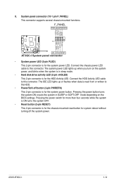
... without turning off button (2-pin PWRBTN) This 2-pin connector is for the system power LED. ASUS AT3GC-I Reset Ground IDE_LEDIDE_LED+ 8. GND PWR PLEDPLED+ AT3GC-I 1-12 F_PANEL PWR LED PWR BTN PIN 1 HD_LED RESET AT3GC-I System panel connector • System power LED (2-pin PLED) This 2-pin connector is read... from or written to this connector. The IDE LED lights up when you turn on the BIOS settings. System panel connector (10-1 pin F_PANEL...
... without turning off button (2-pin PWRBTN) This 2-pin connector is for the system power LED. ASUS AT3GC-I Reset Ground IDE_LEDIDE_LED+ 8. GND PWR PLEDPLED+ AT3GC-I 1-12 F_PANEL PWR LED PWR BTN PIN 1 HD_LED RESET AT3GC-I System panel connector • System power LED (2-pin PLED) This 2-pin connector is read... from or written to this connector. The IDE LED lights up when you turn on the BIOS settings. System panel connector (10-1 pin F_PANEL...

User Manual
Page 22
...PIN 1 PIN 1 MIC2 MICPWR Line out_R NC Line out_L PORT1 L PORT1 R PORT2 R SENSE_SEND PORT2 L AT3GC-I HD-audio-compliant Legacy AC'97 pin definition compliant definition AT3GC-I /O module cable to this connector, ensure that supports either High Definition Audio or AC`97 audio standard.... AT3GC-I CHASSIS GND Chassis Signal +5VSB_MB AT3GC-I /O module that the Front Panel Support Type item in the BIOS is for details. 10. See section 2.4.5 Onboard Devices Configuration for a chassis-mounted...
...PIN 1 PIN 1 MIC2 MICPWR Line out_R NC Line out_L PORT1 L PORT1 R PORT2 R SENSE_SEND PORT2 L AT3GC-I HD-audio-compliant Legacy AC'97 pin definition compliant definition AT3GC-I /O module cable to this connector, ensure that supports either High Definition Audio or AC`97 audio standard.... AT3GC-I CHASSIS GND Chassis Signal +5VSB_MB AT3GC-I /O module that the Front Panel Support Type item in the BIOS is for details. 10. See section 2.4.5 Onboard Devices Configuration for a chassis-mounted...

User Manual
Page 24
..., select either through the Internet. Click the Utilities tab, then click Install ASUS Update. 3. Quit all its features. 2-1 ASUS AT3GC-I The ASUS Update utility is a utility that comes with the motherboard package. Chapter 2 BIOS information 2.1 Managing and updating your BIOS Save a copy of the original motherboard BIOS file to a USB flash disk in case you want to download then...
..., select either through the Internet. Click the Utilities tab, then click Install ASUS Update. 3. Quit all its features. 2-1 ASUS AT3GC-I The ASUS Update utility is a utility that comes with the motherboard package. Chapter 2 BIOS information 2.1 Managing and updating your BIOS Save a copy of the original motherboard BIOS file to a USB flash disk in case you want to download then...
User Manual
Page 25
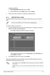
...Press . Updating from the Open window, then click Open. 3. Locate the BIOS file from a BIOS file a. Press to display the following: ASUSTek EZ Flash 2 BIOS ROM Utility V3.37 FLASH TYPE: MXIC 25L8005 Current ROM BOARD: AT3GC-I VER: 0204 (H:00 B:00) DATE: 05/20/2009 Update ROM BOARD... the updating process. 2.1.2 ASUS EZ Flash 2 utility The ASUS EZ Flash 2 feature allows you to update the BIOS without using EZ Flash 2: 1. Select Update BIOS from the ASUS website at www.asus.com. To update the BIOS using an OS‑based utility. Download the latest BIOS file from a file, ...
...Press . Updating from the Open window, then click Open. 3. Locate the BIOS file from a BIOS file a. Press to display the following: ASUSTek EZ Flash 2 BIOS ROM Utility V3.37 FLASH TYPE: MXIC 25L8005 Current ROM BOARD: AT3GC-I VER: 0204 (H:00 B:00) DATE: 05/20/2009 Update ROM BOARD... the updating process. 2.1.2 ASUS EZ Flash 2 utility The ASUS EZ Flash 2 feature allows you to update the BIOS without using EZ Flash 2: 1. Select Update BIOS from the ASUS website at www.asus.com. To update the BIOS using an OS‑based utility. Download the latest BIOS file from a file, ...
User Manual
Page 26
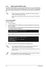
... cause system boot failure! Reading file "AT3GC-I Download the latest BIOS file from the ASUS website at www.asus.com. 2-3 ASUS AT3GC-I .ROM". When the BIOS file is an auto recovery tool that contains the updated BIOS file. • Prepare the motherboard Support DVD or a USB flash disk containing the updated motherboard BIOS before using this motherboard. Start Erasing... Restart the system...
... cause system boot failure! Reading file "AT3GC-I Download the latest BIOS file from the ASUS website at www.asus.com. 2-3 ASUS AT3GC-I .ROM". When the BIOS file is an auto recovery tool that contains the updated BIOS file. • Prepare the motherboard Support DVD or a USB flash disk containing the updated motherboard BIOS before using this motherboard. Start Erasing... Restart the system...

User Manual
Page 27
... system off then back on your screen. • Visit the ASUS website at www.asus.com to download the latest BIOS file for this motherboard. 2.3 Main menu When you enter the BIOS Setup program, the Main menu screen appears, giving you are for this motherboard apply to most conditions to set the system date. Select the...
... system off then back on your screen. • Visit the ASUS website at www.asus.com to download the latest BIOS file for this motherboard. 2.3 Main menu When you enter the BIOS Setup program, the Main menu screen appears, giving you are for this motherboard apply to most conditions to set the system date. Select the...
User Manual
Page 28
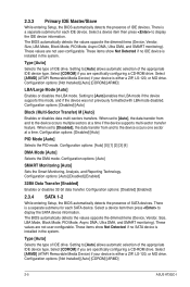
...] Enables or disables 32-bit data transfer. Configuration options: [Disabled] [Enabled] 2.3.4 SATA 1-2 While entering Setup, the BIOS automatically detects the presence of IDE devices. Select [ARMD] (ATAPI Removable Media Device) if your device is either a ZIP.... Configuration options: [Auto] SMART Monitoring [Auto] Sets the Smart Monitoring, Analysis, and Reporting Technology. The BIOS automatically detects the values opposite the dimmed items (Device, Vendor, Size, LBA Mode, Block Mode, PIO Mode.... Configuration options: [Not Installed] [Auto] [CDROM] [ARMD] 2-5 ASUS AT3GC-I
...] Enables or disables 32-bit data transfer. Configuration options: [Disabled] [Enabled] 2.3.4 SATA 1-2 While entering Setup, the BIOS automatically detects the presence of IDE devices. Select [ARMD] (ATAPI Removable Media Device) if your device is either a ZIP.... Configuration options: [Auto] SMART Monitoring [Auto] Sets the Smart Monitoring, Analysis, and Reporting Technology. The BIOS automatically detects the values opposite the dimmed items (Device, Vendor, Size, LBA Mode, Block Mode, PIO Mode.... Configuration options: [Not Installed] [Auto] [CDROM] [ARMD] 2-5 ASUS AT3GC-I

User Manual
Page 29
...the LBA mode if the device supports this menu. AMI BIOS Displays the auto-detected BIOS information Processor Displays the auto-detected CPU specification System Memory Displays the auto-detected system memory ...Chapter 2: BIOS information 2-6 Setting to display the sub-menu. Configuration options: [Disabled] [Auto] ... Mode [Auto] Enables or disables the LBA mode. The BIOS automatically detects the items in this mode, and if the device was not previously formatted with LBA mode disabled....
...the LBA mode if the device supports this menu. AMI BIOS Displays the auto-detected BIOS information Processor Displays the auto-detected CPU specification System Memory Displays the auto-detected system memory ...Chapter 2: BIOS information 2-6 Setting to display the sub-menu. Configuration options: [Disabled] [Auto] ... Mode [Auto] Enables or disables the LBA mode. The BIOS automatically detects the items in this mode, and if the device was not previously formatted with LBA mode disabled....
User Manual
Page 30
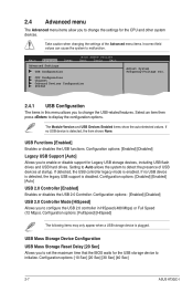
...the system to malfunction. If no USB device is enabled. Configuration options: [10 Sec] [20 Sec] [30 Sec] [40 Sec] 2-7 ASUS AT3GC-I Take caution when changing the settings of USB devices at startup. USB Functions [Enabled] Enables or disables the USB functions. Configuration options: [... to change the settings for Legacy USB storage devices, including USB flash drives and USB hard drives. Main Advanced Power BIOS SETUP UTILITY Boot Tools Exit Advanced Settings USB Configuration CPU Configuration Chipset Onboard Devices Configuration PCIPnP Adjust System Frequency/Voltage etc....
...the system to malfunction. If no USB device is enabled. Configuration options: [10 Sec] [20 Sec] [30 Sec] [40 Sec] 2-7 ASUS AT3GC-I Take caution when changing the settings of USB devices at startup. USB Functions [Enabled] Enables or disables the USB functions. Configuration options: [... to change the settings for Legacy USB storage devices, including USB flash drives and USB hard drives. Main Advanced Power BIOS SETUP UTILITY Boot Tools Exit Advanced Settings USB Configuration CPU Configuration Chipset Onboard Devices Configuration PCIPnP Adjust System Frequency/Voltage etc....
User Manual
Page 31
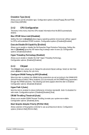
...[Disabled] forces the XD feature flag to always return to change the advanced chipset settings. Configuration options: [Internal VGA] [PCI/Int-VGA] Chapter 2: BIOS information 2-8 Select an item then press to the DRAM SPD (Serial Presence Detect). Configuration options: [Disabled] [Enabled] Hyper Threading Technology [Enabled] Allows ... through the DRAM sub-items. The following sub-items appear when this menu show the CPU-related information that the BIOS automatically detects. Emulation Type [Auto] Allows you to enable or disable the Intel® Hyper Threading Technology.
...[Disabled] forces the XD feature flag to always return to change the advanced chipset settings. Configuration options: [Internal VGA] [PCI/Int-VGA] Chapter 2: BIOS information 2-8 Select an item then press to the DRAM SPD (Serial Presence Detect). Configuration options: [Disabled] [Enabled] Hyper Threading Technology [Enabled] Allows ... through the DRAM sub-items. The following sub-items appear when this menu show the CPU-related information that the BIOS automatically detects. Emulation Type [Auto] Allows you to enable or disable the Intel® Hyper Threading Technology.

User Manual
Page 33
...an IRQ. Configuration options: [32] [64] [96] [128] [160] [192] [224] [248] Allocate IRQ to PCI VGA [Yes] When set to [No], BIOS configures all the devices in the system. Configuration options: [Disabled] [Enabled] IRQ-xx assigned to [PCI Device] When set to [Reserved], the IRQ is reserved... and if you to change the advanced settings for PCI/PnP devices. Configuration options: [Yes] [No] Palette Snooping [Disabled] When set to [No], BIOS does not assign an IRQ to the PCI VGA card even if requested. Configuration options: [PCI Device] [Reserved] 2.5 Power menu The Power menu items allow...
...an IRQ. Configuration options: [32] [64] [96] [128] [160] [192] [224] [248] Allocate IRQ to PCI VGA [Yes] When set to [No], BIOS configures all the devices in the system. Configuration options: [Disabled] [Enabled] IRQ-xx assigned to [PCI Device] When set to [Reserved], the IRQ is reserved... and if you to change the advanced settings for PCI/PnP devices. Configuration options: [Yes] [No] Palette Snooping [Disabled] When set to [No], BIOS does not assign an IRQ to the PCI VGA card even if requested. Configuration options: [PCI Device] [Reserved] 2.5 Power menu The Power menu items allow...

User Manual
Page 35
... connected to display the sub-menu. Select Ignored if you do not wish to display the detected speed. Select an item then press to the motherboard, the field shows N/A. Configuration options: [Disabled] [Space Bar] [Ctrl-Esc] [Power Key] Power On By PS/2 Mouse [Disabled] When set ...and displays the chassis fan speed in rotations per minute (RPM). Power on the system. Main Advanced Boot Settings Power Boot Device Priority BIOS SETUP UTILITY Boot Tools Exit Boot Settings Configuration Security Specifies the Boot Device Priority sequence. VCORE Voltage, 3.3V Voltage, 5V Voltage, 12V ...
... connected to display the sub-menu. Select Ignored if you do not wish to display the detected speed. Select an item then press to the motherboard, the field shows N/A. Configuration options: [Disabled] [Space Bar] [Ctrl-Esc] [Power Key] Power On By PS/2 Mouse [Disabled] When set ...and displays the chassis fan speed in rotations per minute (RPM). Power on the system. Main Advanced Boot Settings Power Boot Device Priority BIOS SETUP UTILITY Boot Tools Exit Boot Settings Configuration Security Specifies the Boot Device Priority sequence. VCORE Voltage, 3.3V Voltage, 5V Voltage, 12V ...


