

User Manual
Page 4
...1-23 1.12 1-24 BIOS 2.1 BIOS 2-3 2.1.1 2-3 2.1.2 AFUDOS BIOS 2-3 2.1.3 EZ Flash BIOS 2-5 2.1.4 CrashFree BIOS2 2-6 2.2 BIOS 2-8 2.2.1 BIOS 2-9 2.3 Main Menu 2-11 2.3.1 IDE Primary/Secondary/Third/Fourth IDE Master/Slave 2-12 2.3.2 IDE IDE Configuration 2-13 2.3.3 System Infomation 2-15 2.4 Advanced Menu 2-15 2.4.1 CPU Configuration 2-16 2.4.2 Chipset 2-16 2.4.3 OnBoard Devices Configuration 2-19 2.4.4 PCI PCI PnP 2-20 2.4.5 USB USB Configuration 2-22 2.5 2.5.1 2.5.2 Power Menu 2-24 APM Configuration 2-25 Hardware Monitor 2-27 4
...1-23 1.12 1-24 BIOS 2.1 BIOS 2-3 2.1.1 2-3 2.1.2 AFUDOS BIOS 2-3 2.1.3 EZ Flash BIOS 2-5 2.1.4 CrashFree BIOS2 2-6 2.2 BIOS 2-8 2.2.1 BIOS 2-9 2.3 Main Menu 2-11 2.3.1 IDE Primary/Secondary/Third/Fourth IDE Master/Slave 2-12 2.3.2 IDE IDE Configuration 2-13 2.3.3 System Infomation 2-15 2.4 Advanced Menu 2-15 2.4.1 CPU Configuration 2-16 2.4.2 Chipset 2-16 2.4.3 OnBoard Devices Configuration 2-19 2.4.4 PCI PCI PnP 2-20 2.4.5 USB USB Configuration 2-22 2.5 2.5.1 2.5.2 Power Menu 2-24 APM Configuration 2-25 Hardware Monitor 2-27 4
User Manual
Page 34
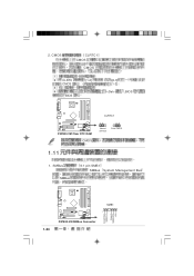
CMOS CLRTC1 CMOS CMOS 1 2 CLRTC CMOS 3 4 BIOS [1-2] [2-3] [1-2] BIOS P4P800-VM ® P4P800-VM Clear RTC RAM CMOS CLRTC1 12 Normal (Default) 23 Clear CMOS 1.11 1. 2. SMBus SMBus 6-1 pin SMB1 SMBus System Management Bus P4P800-VM FLOATING SMBCLK Ground SMBDATA +3V 1-24 SMB1 ® 1 P4P800-VM SMBus Connector
CMOS CLRTC1 CMOS CMOS 1 2 CLRTC CMOS 3 4 BIOS [1-2] [2-3] [1-2] BIOS P4P800-VM ® P4P800-VM Clear RTC RAM CMOS CLRTC1 12 Normal (Default) 23 Clear CMOS 1.11 1. 2. SMBus SMBus 6-1 pin SMB1 SMBus System Management Bus P4P800-VM FLOATING SMBCLK Ground SMBDATA +3V 1-24 SMB1 ® 1 P4P800-VM SMBus Connector
User Manual
Page 38
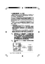
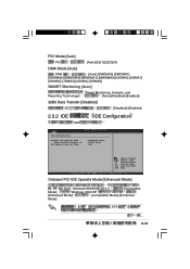
... IDE Operate Mode Enhanced Mode Compatible Mode Compatible Mode Compatible Mode Enhanced Mode Support On S-ATA - - - P-ATA & S-ATA P-ATA & S-ATA P-ATA Only Windows 2000/XP Mode S-ATA ATA BIOS 2 Enhanced ATA 4 6. 20-pin ATXPWR1, 4-pin ATX12V1 ATX 12V 20 ATXPWR1 +12V 8 230 ATX 12V 1 300 +12V +5VSB 4-pin ATX12V ATXPWR1 P4P800-VM ATX12V1 GND +12V DC GND +12V DC ® P4P800-VM ATX Power Connector +3.3VDC...
... IDE Operate Mode Enhanced Mode Compatible Mode Compatible Mode Compatible Mode Enhanced Mode Support On S-ATA - - - P-ATA & S-ATA P-ATA & S-ATA P-ATA Only Windows 2000/XP Mode S-ATA ATA BIOS 2 Enhanced ATA 4 6. 20-pin ATXPWR1, 4-pin ATX12V1 ATX 12V 20 ATXPWR1 +12V 8 230 ATX 12V 1 300 +12V +5VSB 4-pin ATX12V ATXPWR1 P4P800-VM ATX12V1 GND +12V DC GND +12V DC ® P4P800-VM ATX Power Connector +3.3VDC...

User Manual
Page 49
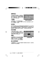
Floppy found ! 4. Reading file "P4P800VM.rom". EZ Flash BIOS User recovery requested. Completed. EZ Flash EZ Flash BIOS 1. Starting BIOS recovery... Start flashing... Rebooting. 2-5 Checking for floppy... BIOS Flash 2. 3. Checking for floppy... BIOS P4P800VM.rom EZ POST + EZ Flash User recovery requested. Starting BIOS recovery... 2.1.3 EZ Flash BIOS EZ Flash BIOS On Self Test POST DOS BIOS + EZ Flash Power- Floppy not found P4P800VM.ROM not found ! Flashed successfully.
Floppy found ! 4. Reading file "P4P800VM.rom". EZ Flash BIOS User recovery requested. Completed. EZ Flash EZ Flash BIOS 1. Starting BIOS recovery... Start flashing... Rebooting. 2-5 Checking for floppy... BIOS Flash 2. 3. Checking for floppy... BIOS P4P800VM.rom EZ POST + EZ Flash User recovery requested. Starting BIOS recovery... 2.1.3 EZ Flash BIOS EZ Flash BIOS On Self Test POST DOS BIOS + EZ Flash Power- Floppy not found P4P800VM.ROM not found ! Flashed successfully.
User Manual
Page 54
... Configuration System Information [18:29:27] [Wed 03/19/2003] [1.44M, 3.5 in the sections below may cause system to CAS# Delay DRAM Precharge Delay DRAM Burst Length [Disabled] [2.5 Clocks] [4 Clocks] [4 Clocks] [8 Clocks] [8 Clocks] Graphic Adapter Priority Graphics Aperture Size Spread Spectrum ICH Delayed Transaction MPS Revision [AGP/PCI] [ 64 MB] [Enabled] [Enabled] [1.4] Select Screen Select Item +- Select Screen Select Item +- Use...
... Configuration System Information [18:29:27] [Wed 03/19/2003] [1.44M, 3.5 in the sections below may cause system to CAS# Delay DRAM Precharge Delay DRAM Burst Length [Disabled] [2.5 Clocks] [4 Clocks] [4 Clocks] [8 Clocks] [8 Clocks] Graphic Adapter Priority Graphics Aperture Size Spread Spectrum ICH Delayed Transaction MPS Revision [AGP/PCI] [ 64 MB] [Enabled] [Enabled] [1.4] Select Screen Select Item +- Select Screen Select Item +- Use...
User Manual
Page 56
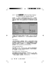
... Master/Slave BIOS ATA IDE IDE ATA [Enter] Primary IDE Master Device : Hard Disk Vendor : ST320413A Size : 20.0GB LBA Mode : Supported Block Mode : 16 Sectors PIO Mode : Supported Async DMA : MultiWord DMA-2 Ultra DMA : Ultra DMA-5 SMART Monitoring: Supported Type LBA/Large Mode Block (Multi-sector Transfer) PIO Mode DMA Mode Smart Monitoring 32Bit Data Transfer [Auto] [Auto] [Auto] [Auto] [Auto] [Auto] [Disabled] Select the type of device connected to...
... Master/Slave BIOS ATA IDE IDE ATA [Enter] Primary IDE Master Device : Hard Disk Vendor : ST320413A Size : 20.0GB LBA Mode : Supported Block Mode : 16 Sectors PIO Mode : Supported Async DMA : MultiWord DMA-2 Ultra DMA : Ultra DMA-5 SMART Monitoring: Supported Type LBA/Large Mode Block (Multi-sector Transfer) PIO Mode DMA Mode Smart Monitoring 32Bit Data Transfer [Auto] [Auto] [Auto] [Auto] [Auto] [Auto] [Disabled] Select the type of device connected to...
User Manual
Page 57
....0 [Compatible Mode] Windows 2000/XP [Enhanced Mode] [Compatible Mode] [Enhanced Mode] 1-26 ATA ... 2-13 PIO Mode [Auto] PIO [Auto] [0] [1] [2] [3] [4] DMA Mode [Auto] DMA [Auto] [SWDMA0] [SWDMA1] [SWDMA2] [MWDMA0] [MWDMA1] [MWDMA2] [UDMA0] [UDMA1] [UDMA2] [UDMA3] [UDMA4] [UDMA5] SMART Monitoring [Auto] Reporting Technology Smart Monitoring, Analysis, and [Auto] [Disabled] [Enabled] 32Bit Data Transfer [Disabled] 32 [Disabled] [Enabled] 2.3.2 IDE IDE IDE Configuration IDE Configuration Onboard IDE Operate Mode Enhanced Mode Support On IDE...
....0 [Compatible Mode] Windows 2000/XP [Enhanced Mode] [Compatible Mode] [Enhanced Mode] 1-26 ATA ... 2-13 PIO Mode [Auto] PIO [Auto] [0] [1] [2] [3] [4] DMA Mode [Auto] DMA [Auto] [SWDMA0] [SWDMA1] [SWDMA2] [MWDMA0] [MWDMA1] [MWDMA2] [UDMA0] [UDMA1] [UDMA2] [UDMA3] [UDMA4] [UDMA5] SMART Monitoring [Auto] Reporting Technology Smart Monitoring, Analysis, and [Auto] [Disabled] [Enabled] 32Bit Data Transfer [Disabled] 32 [Disabled] [Enabled] 2.3.2 IDE IDE IDE Configuration IDE Configuration Onboard IDE Operate Mode Enhanced Mode Support On IDE...

User Manual
Page 59
Select Screen Select Item Enter Go to Sub-screen F1 General Help F10 Save and Exit ESC Exit 2-15 2.3.3 System Information BIOS AMI BIOS Version : 08.00.09 Build Date : 03/13/03 ID : xxxxxxxx Processor Type Speed Count : Intel(R) Pentium(R) 4 CPU 1.73GHz : 1733 MHz : 1 System Memory Size : 256MB AMI BIOS Processor BIOS Select Screen Select Item +- Change Option F1 General Help F10 Save and Exit ESC Exit System Memory 2.4 Advanced menu CPU Configuration Chipset Onboard Devices Configuration PCI PnP USB Configuration Configure CPU.
Select Screen Select Item Enter Go to Sub-screen F1 General Help F10 Save and Exit ESC Exit 2-15 2.3.3 System Information BIOS AMI BIOS Version : 08.00.09 Build Date : 03/13/03 ID : xxxxxxxx Processor Type Speed Count : Intel(R) Pentium(R) 4 CPU 1.73GHz : 1733 MHz : 1 System Memory Size : 256MB AMI BIOS Processor BIOS Select Screen Select Item +- Change Option F1 General Help F10 Save and Exit ESC Exit System Memory 2.4 Advanced menu CPU Configuration Chipset Onboard Devices Configuration PCI PnP USB Configuration Configure CPU.
User Manual
Page 60
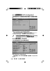
...] [Enabled] Boot Display Device Flat Panel Type TV Standard [Auto] [640x480 LVDS] [Auto] MPS Revision [1.4] Set the CPU external frequency for next boot. Change Option F1 General Help F10 Save and Exit ESC Exit Hyper-Threading Technology [Enabled] Threading Technology Hyper[Enabled] [Disabled] Technology) Intel Pentium 4 2.4.2 Chipset (Hyper-Threading Advanced Chipset settings WARNING: Setting wrong values in the sections below may cause system to malfunction. 2.4.1 CPU Configuration Configure advanced CPU settings Manufacturer...
...] [Enabled] Boot Display Device Flat Panel Type TV Standard [Auto] [640x480 LVDS] [Auto] MPS Revision [1.4] Set the CPU external frequency for next boot. Change Option F1 General Help F10 Save and Exit ESC Exit Hyper-Threading Technology [Enabled] Threading Technology Hyper[Enabled] [Disabled] Technology) Intel Pentium 4 2.4.2 Chipset (Hyper-Threading Advanced Chipset settings WARNING: Setting wrong values in the sections below may cause system to malfunction. 2.4.1 CPU Configuration Configure advanced CPU settings Manufacturer...

User Manual
Page 61
... Frequency [Auto] [400MHz] [Auto] [266MHz] [333MHz] Configure DRAM Timing by SPD [Enabled] SPD Serial Presence Detect [Disabled] [Enabled] Configure DRAM Timing by SPD [Disabled] DRAM CAS# Latency [2.5 Clocks] SDRAM [2.0 Clocks][2.5 Clocks][3.0...] DRAM Burst Length [8 Clocks] [8 Clocks][4 Clocks] Internal Graphic Accelerate Mode [Auto] [Auto] Graphic Adapter Priority [AGP/Int-VGA] [2T] [1T] [Internal VGA] [AGP/Int-VGA] [AGP/PCI] [PCI/AGP] [PCI/Int-VGA] Onboard Video Memory [Enabled, 8MB] [Disabled] [Enabled, 1MB] [Enabled, 4MB] [Enabled, 8MB] [Enabled, 16MB] [Enabled, 32MB] 2-17
... Frequency [Auto] [400MHz] [Auto] [266MHz] [333MHz] Configure DRAM Timing by SPD [Enabled] SPD Serial Presence Detect [Disabled] [Enabled] Configure DRAM Timing by SPD [Disabled] DRAM CAS# Latency [2.5 Clocks] SDRAM [2.0 Clocks][2.5 Clocks][3.0...] DRAM Burst Length [8 Clocks] [8 Clocks][4 Clocks] Internal Graphic Accelerate Mode [Auto] [Auto] Graphic Adapter Priority [AGP/Int-VGA] [2T] [1T] [Internal VGA] [AGP/Int-VGA] [AGP/PCI] [PCI/AGP] [PCI/Int-VGA] Onboard Video Memory [Enabled, 8MB] [Disabled] [Enabled, 1MB] [Enabled, 4MB] [Enabled, 8MB] [Enabled, 16MB] [Enabled, 32MB] 2-17
User Manual
Page 64
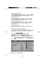
Change Option F1 General Help F10 Save and Exit ESC Exit 2-20 BIOS YES: Lets the operating system configure Plug and Play (PnP) devices not required for boot if your system has a Plug and Play operating system. Select Screen Select Item +- Plug and Play OS PCI Latency Timer Allocate IRQ to malfunction. Parallel Port Mode [ECP] Parallel Port Address 278 Normal EPP [Normal] [Bi-directional] [EPP] [ECP...
Change Option F1 General Help F10 Save and Exit ESC Exit 2-20 BIOS YES: Lets the operating system configure Plug and Play (PnP) devices not required for boot if your system has a Plug and Play operating system. Select Screen Select Item +- Plug and Play OS PCI Latency Timer Allocate IRQ to malfunction. Parallel Port Mode [ECP] Parallel Port Address 278 Normal EPP [Normal] [Bi-directional] [EPP] [ECP...

User Manual
Page 69
... Min] [30 Min] [40 Min] [50 Min] [60 Min] 2-25 2.5.1 APM Configuration APM Configuration Power Management/APM Video Power Down Mode Hard Disk Power Down Mode Standby Time Out Suspend Time Out Throttle Slow Clock Ratio System Thermal Power Button Mode Restore on AC Power Loss Power On By PS/2 Devices Power On By External Modem Power On By PCI Devices Power On By RTC Alarm [Enabled] [Suspend] [Suspend] [Disabled] [Disabled] [50%] [Disabled] [On/Off] [Power Off] [Disabled] [Disabled] [Disabled] [Disabled] Enabled or disable APM.
... Min] [30 Min] [40 Min] [50 Min] [60 Min] 2-25 2.5.1 APM Configuration APM Configuration Power Management/APM Video Power Down Mode Hard Disk Power Down Mode Standby Time Out Suspend Time Out Throttle Slow Clock Ratio System Thermal Power Button Mode Restore on AC Power Loss Power On By PS/2 Devices Power On By External Modem Power On By PCI Devices Power On By RTC Alarm [Enabled] [Suspend] [Suspend] [Disabled] [Disabled] [50%] [Disabled] [On/Off] [Power Off] [Disabled] [Disabled] [Disabled] [Disabled] Enabled or disable APM.

User Manual
Page 71
... Alarm Date RTC Alarm Hour RTC Alarm Second [Disabled] [Enabled] RTC 2.5.2 Hardware Monitor Hardware Monitor CPU Temperature MB Temperature CPU Fan Speed Chassis Fan Speed VCORE Voltage 3.3V Voltage 5V Voltage 12V Voltage [44°C/111°F] [36°C/96.5°F] [2250RPM] [XXX RPM] [1.550V] [3.386V] [4.890V] [11.900V] CPU temperature Select Screen Select Item +- Change Option F1 General Help F10 Save and Exit ESC Exit...
... Alarm Date RTC Alarm Hour RTC Alarm Second [Disabled] [Enabled] RTC 2.5.2 Hardware Monitor Hardware Monitor CPU Temperature MB Temperature CPU Fan Speed Chassis Fan Speed VCORE Voltage 3.3V Voltage 5V Voltage 12V Voltage [44°C/111°F] [36°C/96.5°F] [2250RPM] [XXX RPM] [1.550V] [3.386V] [4.890V] [11.900V] CPU temperature Select Screen Select Item +- Change Option F1 General Help F10 Save and Exit ESC Exit...
User Manual
Page 72
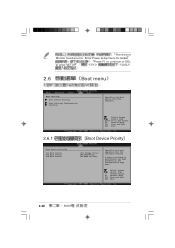
... Item Enter Go to Sub-screen F1 General Help F10 Save and Exit ESC Exit Boot Device Priority [1st Floppy Drive] [PM-ST320413A] [PS-ASUS CD-S340] Specifies the boot sequence from the available devices. Select Screen Select Item +- Change Option F1 General Help F10 Save and Exit ESC Exit 2-28 BIOS : Hardware Monitor found an error. A device enclosed in parenthesis has been disabled in the corresponding type menu.
... Item Enter Go to Sub-screen F1 General Help F10 Save and Exit ESC Exit Boot Device Priority [1st Floppy Drive] [PM-ST320413A] [PS-ASUS CD-S340] Specifies the boot sequence from the available devices. Select Screen Select Item +- Change Option F1 General Help F10 Save and Exit ESC Exit 2-28 BIOS : Hardware Monitor found an error. A device enclosed in parenthesis has been disabled in the corresponding type menu.
User Manual
Page 73
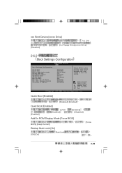
... will decrease the time needed to skip certain tests while booting. xxx Boot Device [xxxxx Drive] 3rd [Disabled] 1st, 2nd , [1st Floppy Drive][xxxxx Drive] 2.6.2 Boot Settings Configuration Boot Settings Configuration Quick Boot Quiet Boot Add On ROM Display Mode Bootup Num-Lock PS/2 Mouse Support Typematic Rate Parity Check Boot to OS/2 Wait for 'F1' If Error Hit 'DEL' Message Display Interrupt 19 Capture [Enabled] [Enabled] [Force BIOS] [On] [Enabled] [Fast] [Disabled] [No] [Enabled] [Enabled] [Disabled] Allows BIOS to boot the system. Select Screen Select Item +-
... will decrease the time needed to skip certain tests while booting. xxx Boot Device [xxxxx Drive] 3rd [Disabled] 1st, 2nd , [1st Floppy Drive][xxxxx Drive] 2.6.2 Boot Settings Configuration Boot Settings Configuration Quick Boot Quiet Boot Add On ROM Display Mode Bootup Num-Lock PS/2 Mouse Support Typematic Rate Parity Check Boot to OS/2 Wait for 'F1' If Error Hit 'DEL' Message Display Interrupt 19 Capture [Enabled] [Enabled] [Force BIOS] [On] [Enabled] [Fast] [Disabled] [No] [Enabled] [Enabled] [Disabled] Allows BIOS to boot the system. Select Screen Select Item +-
User Manual
Page 74
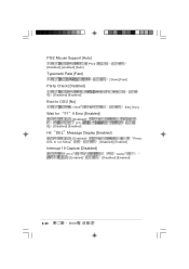
PS/2 Mouse Support [Auto] PS/2 [Disabled] [enabled] [Auto] Typematic Rate [Fast] Parity Check [Disabled] [Slow] [Fast] [Disabled] [Enabled] Boot to OS/2 [No] OS/2 [No] [Yes] Wait for F1 If Error [Enabled] [Enabled] [F1] [Disabled] [Enabled] Hit DEL Message Display [Enabled] [Enabled] DEL to run Setup [Disabled] [Enabled] Press Interrupt 19 Capture [Disabled] PCI [Enabled] SCSI [Disabled] [Enabled] 2-30 BIOS
PS/2 Mouse Support [Auto] PS/2 [Disabled] [enabled] [Auto] Typematic Rate [Fast] Parity Check [Disabled] [Slow] [Fast] [Disabled] [Enabled] Boot to OS/2 [No] OS/2 [No] [Yes] Wait for F1 If Error [Enabled] [Enabled] [F1] [Disabled] [Enabled] Hit DEL Message Display [Enabled] [Enabled] DEL to run Setup [Disabled] [Enabled] Press Interrupt 19 Capture [Disabled] PCI [Enabled] SCSI [Disabled] [Enabled] 2-30 BIOS
User Manual
Page 75
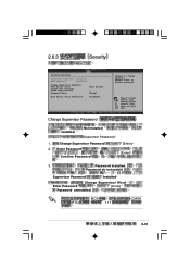
...) BIOS 1.11 CMOS 2-31 Password do not match! Change Option F1 General Help F10 Save and Exit ESC Exit Change Supervisor Password Installed Not Installed (Supervisor Password) 1. Enter Password Confirm Password [Enter] [Enter] 3. Select Screen Select Item +- Password Installed. again to change password. 2.6.3 Security Security Settings Supervisor Password :Installed User Password :Installed Change Supervisor Password User Access Level Change User Password Clear User Password Password Check [Full Access] [Setup] Boot Sector Virus Protection [Disabled] to...
...) BIOS 1.11 CMOS 2-31 Password do not match! Change Option F1 General Help F10 Save and Exit ESC Exit Change Supervisor Password Installed Not Installed (Supervisor Password) 1. Enter Password Confirm Password [Enter] [Enter] 3. Select Screen Select Item +- Password Installed. again to change password. 2.6.3 Security Security Settings Supervisor Password :Installed User Password :Installed Change Supervisor Password User Access Level Change User Password Clear User Password Password Check [Full Access] [Setup] Boot Sector Virus Protection [Disabled] to...
User Manual
Page 76
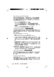
User Access Level [Full Access] BIOS BIOS Only] [Limited] [Full Access] No Access View Only Limited BIOS BIOS BIOS [No Access] [View Full Access Change User Password BIOS Installed Not Installed (User Password) 1. Change User Password 2. Password do not match! Password Installed. Clear User Password RTC CMOS 1.11 User Enter Password Check [Setup] [Setup] BIOS BIOS [Always] BIOS [Setup] [Always] 2-32 BIOS Enter Password Confirm Password [Enter] [Enter] 3. Password Installed Change User Word Password [Enter] Password uninstalled.
User Access Level [Full Access] BIOS BIOS Only] [Limited] [Full Access] No Access View Only Limited BIOS BIOS BIOS [No Access] [View Full Access Change User Password BIOS Installed Not Installed (User Password) 1. Change User Password 2. Password do not match! Password Installed. Clear User Password RTC CMOS 1.11 User Enter Password Check [Setup] [Setup] BIOS BIOS [Always] BIOS [Setup] [Always] 2-32 BIOS Enter Password Confirm Password [Enter] [Enter] 3. Password Installed Change User Word Password [Enter] Password uninstalled.
User Manual
Page 77
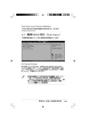
Select Screen Select Item Enter Go to Sub-screen F1 General Help F10 Save and Exit ESC Exit Exit Saving Changes BIOS CMOS [OK] [Cancel] Enter CMOS BIOS BIOS BIOS Esc BIOS Discard configuration changes and exit now? [OK] BIOS [Cancel] BIOS 2-33 F10 key can be used for this operation. Boot Sector Virus Protection [Disabled] [Disabledc] [Enabled] 2.7 BIOS BIOS Exit menu BIOS Exit Options Exit & Save Changes Exit & Discard Changes Discard Changes Load Setup Defaults Exit system setup after saving the changes.
Select Screen Select Item Enter Go to Sub-screen F1 General Help F10 Save and Exit ESC Exit Exit Saving Changes BIOS CMOS [OK] [Cancel] Enter CMOS BIOS BIOS BIOS Esc BIOS Discard configuration changes and exit now? [OK] BIOS [Cancel] BIOS 2-33 F10 key can be used for this operation. Boot Sector Virus Protection [Disabled] [Disabledc] [Enabled] 2.7 BIOS BIOS Exit menu BIOS Exit Options Exit & Save Changes Exit & Discard Changes Discard Changes Load Setup Defaults Exit system setup after saving the changes.

User Manual
Page 82
3.2.2 Drivers menu Intel Chipset Inf Update Window INF INF INF Intel® Extreme Intel Extreme USB 2.0 USB 2.0 SoundMAX AD1980 SoundMAX SoundMAX SoundMAX Intel PRO/100 Intel PRO/100 3-4 SoundMax
3.2.2 Drivers menu Intel Chipset Inf Update Window INF INF INF Intel® Extreme Intel Extreme USB 2.0 USB 2.0 SoundMAX AD1980 SoundMAX SoundMAX SoundMAX Intel PRO/100 Intel PRO/100 3-4 SoundMax


