
AP1710-S5 English Manual
Page 2
... for informational use or data, interruption of business and the like), even if ASUS has been advised of the possibility of ASUSTeK COMPUTER INC. ("ASUS"). Product Name: Manual Edition: Release Date: ASUS AP1710-S5 First Edition V1 (E1346) July 2003 ii No part of alteration is defaced or... missing. ASUS provides this manual ae furnished for any defect or error in this manual...
... for informational use or data, interruption of business and the like), even if ASUS has been advised of the possibility of ASUSTeK COMPUTER INC. ("ASUS"). Product Name: Manual Edition: Release Date: ASUS AP1710-S5 First Edition V1 (E1346) July 2003 ii No part of alteration is defaced or... missing. ASUS provides this manual ae furnished for any defect or error in this manual...
AP1710-S5 English Manual
Page 11
ASUS AP1710-S5 user guide 1-1 It includes sections on front panel and rear panel specifications. Product introduction Chapter 1 This chapter describes the general features of the AP1710-S5 server.
ASUS AP1710-S5 user guide 1-1 It includes sections on front panel and rear panel specifications. Product introduction Chapter 1 This chapter describes the general features of the AP1710-S5 server.

AP1710-S5 English Manual
Page 12
...-S30 Ultra320 dual-channel SCSI RAID card 3. Keys (2 pieces) 6. Documentation • ASUS AP1710-S5 user guide • ASUS PRL-DL user guide • ASUS ASMS (ASMA+ASWM) user guide 1.1.2 Optional items • ASUS AS-35 5U rackmount rail kit • ASUS PXI-G45 Gb LAN Card • LSI MegaRaid 320-I single channel-RAID card 1-2 Chapter 1: Product introduction...
...-S30 Ultra320 dual-channel SCSI RAID card 3. Keys (2 pieces) 6. Documentation • ASUS AP1710-S5 user guide • ASUS PRL-DL user guide • ASUS ASMS (ASMA+ASWM) user guide 1.1.2 Optional items • ASUS AS-35 5U rackmount rail kit • ASUS PXI-G45 Gb LAN Card • LSI MegaRaid 320-I single channel-RAID card 1-2 Chapter 1: Product introduction...
AP1710-S5 English Manual
Page 13
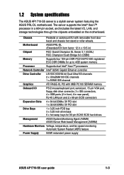
Motherboard ASUS PRL-DL (Extended ATX form factor: 12 in x 10.5 in rear panel), RJ-45 LAN port and 2 x 68-pin SCSI connectors Expansion Slots 4 x 64-bit/...) Hardware Monitors Voltage, temperature, and fan speed monitoring Automatic System Restart (ASR) feature Power Supply 500W redundant power supply ASUS AP1710-S5 user guide 1-3 1.2 System specifications The ASUS AP1710-S5 server is a stylish server system featuring the ASUS PRL-DL motherboard. The server supports the Intel® Xeon™ processor in a 604-pin socket, and includes the...
Motherboard ASUS PRL-DL (Extended ATX form factor: 12 in x 10.5 in rear panel), RJ-45 LAN port and 2 x 68-pin SCSI connectors Expansion Slots 4 x 64-bit/...) Hardware Monitors Voltage, temperature, and fan speed monitoring Automatic System Restart (ASR) feature Power Supply 500W redundant power supply ASUS AP1710-S5 user guide 1-3 1.2 System specifications The ASUS AP1710-S5 server is a stylish server system featuring the ASUS PRL-DL motherboard. The server supports the Intel® Xeon™ processor in a 604-pin socket, and includes the...

AP1710-S5 English Manual
Page 15
Rear panel features The rear panel includes a slot for the motherboard rear I/O ports, six full-length expansion slots, a chassis lock and intrusion switch, a vent for the system fan, and redundant power supply modules. Power supply modules P/S2 mouse port P/S2 keyboard port USB ports Serial port Parallel port VGA port Gigabit LAN port Gigabit LAN card (optional) SCSI card (optional AC IN connector AC Power status LED 12cm fan vent Chassis lock Expansion slots ASUS AP1710-S5 user guide 1-5 1.4.
Rear panel features The rear panel includes a slot for the motherboard rear I/O ports, six full-length expansion slots, a chassis lock and intrusion switch, a vent for the system fan, and redundant power supply modules. Power supply modules P/S2 mouse port P/S2 keyboard port USB ports Serial port Parallel port VGA port Gigabit LAN port Gigabit LAN card (optional) SCSI card (optional AC IN connector AC Power status LED 12cm fan vent Chassis lock Expansion slots ASUS AP1710-S5 user guide 1-5 1.4.
AP1710-S5 English Manual
Page 17
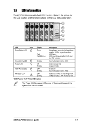
... SAF-TE* function Read/write data into the HDD System power ON Suspend mode No activity Read/write data into the HDD System is closed. ASUS AP1710-S5 user guide 1-7 no incoming event ASMS indicates a HW monitor event The Power, HDD Access and Message LEDs are visible even if the system front bezel... description ! LED Icon Drive Status LED Display Green Red Red-Blinking Drive Activity LED Blinking Power LED HDD Access LED Message LED ! 1.6 LED information The AP1710-S5 comes with five LED indicators.
... SAF-TE* function Read/write data into the HDD System power ON Suspend mode No activity Read/write data into the HDD System is closed. ASUS AP1710-S5 user guide 1-7 no incoming event ASMS indicates a HW monitor event The Power, HDD Access and Message LEDs are visible even if the system front bezel... description ! LED Icon Drive Status LED Display Green Red Red-Blinking Drive Activity LED Blinking Power LED HDD Access LED Message LED ! 1.6 LED information The AP1710-S5 comes with five LED indicators.
AP1710-S5 English Manual
Page 19
Chapter 2 This chapter lists the hardware setup procedures that you have to perform when installing or removing system components. Hardware setup ASUS AP1710-S5 user guide 2-1
Chapter 2 This chapter lists the hardware setup procedures that you have to perform when installing or removing system components. Hardware setup ASUS AP1710-S5 user guide 2-1
AP1710-S5 English Manual
Page 21
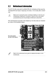
... component or connection. The motherboard is secured in the chassis by nine (9) screws as indicated by circles in the illustration below. ASUS AP1710-S5 user guide 2-3 2.2 Motherboard information The AP1710-S5 comes with the ASUS PRL-DL motherboard that uses the extended ATX form factor measuring 12 inches x 10.5 inches (30.5 x 26.67 cm). Make sure...
... component or connection. The motherboard is secured in the chassis by nine (9) screws as indicated by circles in the illustration below. ASUS AP1710-S5 user guide 2-3 2.2 Motherboard information The AP1710-S5 comes with the ASUS PRL-DL motherboard that uses the extended ATX form factor measuring 12 inches x 10.5 inches (30.5 x 26.67 cm). Make sure...
AP1710-S5 English Manual
Page 23
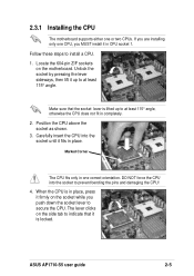
... firmly on the socket while you push down the socket lever to at least 115° angle, otherwise the CPU does not fit in place. ASUS AP1710-S5 user guide 2-5 Carefully insert the CPU into the socket to install a CPU. 1. The lever clicks on the motherboard. Position the CPU above the socket as...
... firmly on the socket while you push down the socket lever to at least 115° angle, otherwise the CPU does not fit in place. ASUS AP1710-S5 user guide 2-5 Carefully insert the CPU into the socket to install a CPU. 1. The lever clicks on the motherboard. Position the CPU above the socket as...
AP1710-S5 English Manual
Page 25
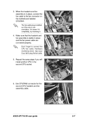
... plug is slotted so it . 4. Don't forget to plug the fan cable. 5. Repeat the same steps if you fail to connect the CPU fan cable. ASUS AP1710-S5 user guide 2-7 3. Make sure that the heatsink and fan assembly is in place and the fan power cable are connected properly. Hardware monitoring errors may...
... plug is slotted so it . 4. Don't forget to plug the fan cable. 5. Repeat the same steps if you fail to connect the CPU fan cable. ASUS AP1710-S5 user guide 2-7 3. Make sure that the heatsink and fan assembly is in place and the fan power cable are connected properly. Hardware monitoring errors may...
AP1710-S5 English Manual
Page 27
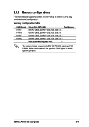
2.4.1 Memory configurations The motherboard supports system memory of up to use only the specified DIMM types for stable system operation. ASUS AP1710-S5 user guide 2-9 Memory configuration table DIMM Socket DDRA1 DDRA2 DDRB1 DDRB2 184-pin ECC DDR DIMM Total Memory SDRAM 128MB, 256MB, 512MB, 1GB, 2GB (x1) = ...
2.4.1 Memory configurations The motherboard supports system memory of up to use only the specified DIMM types for stable system operation. ASUS AP1710-S5 user guide 2-9 Memory configuration table DIMM Socket DDRA1 DDRA2 DDRB1 DDRB2 184-pin ECC DDR DIMM Total Memory SDRAM 128MB, 256MB, 512MB, 1GB, 2GB (x1) = ...
AP1710-S5 English Manual
Page 29
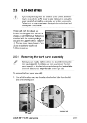
... be connected to an AC power source, make sure to the chassis through four hooked tabs on the upper front part of the front panel. 1 ASUS AP1710-S5 user guide Hooked tab 2-11 The front panel assembly is attached to unplug the power cable before installing or removing any system components. Three 5.25...
... be connected to an AC power source, make sure to the chassis through four hooked tabs on the upper front part of the front panel. 1 ASUS AP1710-S5 user guide Hooked tab 2-11 The front panel assembly is attached to unplug the power cable before installing or removing any system components. Three 5.25...
AP1710-S5 English Manual
Page 31
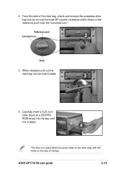
From the side of the drive bay, unlock and remove the screwless drive bay lock by turning the knob 45º counter-clockwise until it is in place. 4 The drive is in place when the screw holes on the drive align with the holes on the reference point near the "unlocked icon." ROM drive) into the bay until it aside. 3 4. Carefully insert a 5.25-inch drive (such as a CD/DVD- When released, pull out the drive bay lock and set it clicks on the side of the bay. ASUS AP1710-S5 user guide 2-13 2. Reference point Unlocked icon 2 Knob 3.
From the side of the drive bay, unlock and remove the screwless drive bay lock by turning the knob 45º counter-clockwise until it is in place. 4 The drive is in place when the screw holes on the drive align with the holes on the reference point near the "unlocked icon." ROM drive) into the bay until it aside. 3 4. Carefully insert a 5.25-inch drive (such as a CD/DVD- When released, pull out the drive bay lock and set it clicks on the side of the bay. ASUS AP1710-S5 user guide 2-13 2. Reference point Unlocked icon 2 Knob 3.

AP1710-S5 English Manual
Page 33
a. Insert the four hinge-like tab ASUS AP1710-S5 user guide 2-15 b. Swing the front panel to the left and fit the four (4) hooked tabs to the left side of the chassis until the tabs snap in place. 7a 7b Hinge-like tabs to the holes on the right edge of the chassis. Re-install the front panel assembly (front bezel and front panel cover). 7.
a. Insert the four hinge-like tab ASUS AP1710-S5 user guide 2-15 b. Swing the front panel to the left and fit the four (4) hooked tabs to the left side of the chassis until the tabs snap in place. 7a 7b Hinge-like tabs to the holes on the right edge of the chassis. Re-install the front panel assembly (front bezel and front panel cover). 7.
AP1710-S5 English Manual
Page 35
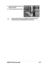
5. Make sure that the HDD tray is completely in place. Push the tray lever back in place before you push the handle back to avoid damaging the drive and the tray. ASUS AP1710-S5 user guide 2-17 Insert the hard disk drive tray into the bay until it fits. 6.
5. Make sure that the HDD tray is completely in place. Push the tray lever back in place before you push the handle back to avoid damaging the drive and the tray. ASUS AP1710-S5 user guide 2-17 Insert the hard disk drive tray into the bay until it fits. 6.
AP1710-S5 English Manual
Page 37
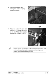
Press the end of the card lock marked "LOCK" to configure any jumpers after installing the expansion card. A light click indicates that it is locked in case you need to secure the card on the slot. 3 4. ASUS AP1710-S5 user guide 2-19 Install the expansion card making sure that the card is properly seated on the slot. Lock 4 4 Refer to the card documentation for the card configuration details, and to the motherboard user guide in place. 3.
Press the end of the card lock marked "LOCK" to configure any jumpers after installing the expansion card. A light click indicates that it is locked in case you need to secure the card on the slot. 3 4. ASUS AP1710-S5 user guide 2-19 Install the expansion card making sure that the card is properly seated on the slot. Lock 4 4 Refer to the card documentation for the card configuration details, and to the motherboard user guide in place. 3.
AP1710-S5 English Manual
Page 39
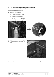
b. Card lock lever Card lock 1a 1b 2. Release the card lock. Press the card lock lever. Press the end of the card lock marked "LOCK" to return it in place. ASUS AP1710-S5 user guide 2-21 Pull out the card from the PCI slot. 2 3. The card lock flips up. a. 2.7.3 Removing an expansion card To remove an expansion card: 1.
b. Card lock lever Card lock 1a 1b 2. Release the card lock. Press the card lock lever. Press the end of the card lock marked "LOCK" to return it in place. ASUS AP1710-S5 user guide 2-21 Pull out the card from the PCI slot. 2 3. The card lock flips up. a. 2.7.3 Removing an expansion card To remove an expansion card: 1.

AP1710-S5 English Manual
Page 41
... side SCSI ID = 0 Disk drive 1 SCSI ID = 1 Disk drive 2 SCSI ID = 2 Disk drive 3 SCSI ID = 3 Disk drive 4 SCSI ID = 4 Disk drive 5 SCSI ID = 5 Disk drive 6 ASUS AP1710-S5 user guide 68-pin SCSI connector (connect to the SCSI connector on the motherboard) SMBus connector (connect to the SMBus connector on the motherboard) HDD...
... side SCSI ID = 0 Disk drive 1 SCSI ID = 1 Disk drive 2 SCSI ID = 2 Disk drive 3 SCSI ID = 3 Disk drive 4 SCSI ID = 4 Disk drive 5 SCSI ID = 5 Disk drive 6 ASUS AP1710-S5 user guide 68-pin SCSI connector (connect to the SCSI connector on the motherboard) SMBus connector (connect to the SMBus connector on the motherboard) HDD...
AP1710-S5 English Manual
Page 43
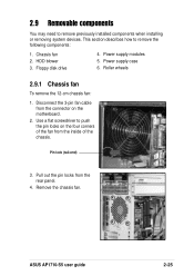
2.9 Removable components You may need to push the pin locks on the motherboard. 2. Floppy disk drive 4. ASUS AP1710-S5 user guide 2-25 HDD blower 3. Chassis fan 2. Power supply modules 5. Pull out the pin locks from the inside of the chassis. Remove the chassis fan. ...
2.9 Removable components You may need to push the pin locks on the motherboard. 2. Floppy disk drive 4. ASUS AP1710-S5 user guide 2-25 HDD blower 3. Chassis fan 2. Power supply modules 5. Pull out the pin locks from the inside of the chassis. Remove the chassis fan. ...

AP1710-S5 English Manual
Page 45
Set aside the cover. 3 4. 2.9.3 Floppy disk drive To remove the floppy disk drive: 1. Remove the front panel assembly. Locate the floppy disk drive cable and power connectors. 4 ASUS AP1710-S5 user guide 2-27 Refer to remove the right side chassis cover screws. 2 3. Use a Phillips head screw driver to "2.5.1 Removing the front panel assembly" on page 2-11. 2. Pull out and detach the right side chassis cover.
Set aside the cover. 3 4. 2.9.3 Floppy disk drive To remove the floppy disk drive: 1. Remove the front panel assembly. Locate the floppy disk drive cable and power connectors. 4 ASUS AP1710-S5 user guide 2-27 Refer to remove the right side chassis cover screws. 2 3. Use a Phillips head screw driver to "2.5.1 Removing the front panel assembly" on page 2-11. 2. Pull out and detach the right side chassis cover.


