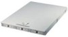
AP140R User Manual English Edition
Page 2
...companies, and are used only for backup purposes, without intent to the owners' benefit, without the express written permission of ASUSTeK COMPUTER INC. ("ASUS"). Manual updates are released for each product design represented by the purchaser for identification or explanation and to infringe. For previous or updated... OF MERCHANTABILITY OR FITNESS FOR A PARTICULAR PURPOSE. The product name and revision number are both printed on the following page. Product Name: AP140R Manual Revision: 1.00 E958 Release Date: Feb 2002 2 Products and corporate names appearing in this...
AP140R User Manual English Edition
Page 3
Contents Disclaimer/Copyrights 2 ASUS Contact Information 6 FCC/CDC Statements 7 Safety Precautions 8 Introduction About This Manual 9 Audience 10 Contents 10 Conventions 11 References 11 System Package Contents 12 Chapter 1 System Overview 13 1.1 System Features 14 1.2 Front Panel Features 15 1.3 Rear Panel ...
AP140R User Manual English Edition
Page 8
... the power supply is broken, do not try to fix it by certified or experienced engineers. • Before operating the server, carefully read all the manuals included with the server package. • Before using the server, make sure all power cables from the existing system before the signal cables are not...
AP140R User Manual English Edition
Page 9
AP140R Server User's Manual 9 About This Manual Introduction "About This Manual" introduces the contents of information that are not contained in this document. It also lists other sources of this manual. This part includes the target audience, chapter description, and conventions used.
AP140R User Manual English Edition
Page 10
...part and try to perform when installing system components. It lists the possible causes of information that you may refer to this manual. Appendix A: Power Supply Information This appendix gives information on the 200-watt switching power supply that you may have to ...solve simple problems before calling customer support. 10 Introduction: About This Manual It includes the target audience, chapter description, and conventions used. Appendix B: Troubleshooting This appendix lists the common problems that comes with...
AP140R User Manual English Edition
Page 11
.... ASUS Motherboard User's Manual The motherboard manual included with this manual. ASUS Websites The ASUS websites worldwide provide updated information on page 6. 3. The ASUS websites are listed in completing a task. Conventions Symbols To make sure that you perform certain tasks properly, take note of the following sources for additional information and for advanced users. 2. AP140R Server User's Manual 11...
AP140R User Manual English Edition
Page 12
...-type Floppy Disk Drive • Front Bezel • CPU Heatsink (without fan) • AC Power Cord • This System User's Manual ASUS NB-LM Motherboard • 32-bit/33MHz PCI Riser Card • Support CD with Drivers and Utilities • Motherboard User...rails • Mounting Ears Assembly • Rail Kit User's Manual ASUS System Management Software CD • System Management Software User's Manual If any of the above items is missing, contact your dealer. 12 Introduction: About This Manual System Package Contents The following checklist enumerates the components included in...
AP140R User Manual English Edition
Page 13
This includes sections on front panel, rear panel, and internal features of the server. System Overview AP140R Server User's Manual 13 Chapter 1 This chapter describes the general features of the server.
AP140R User Manual English Edition
Page 15
AC Power Connector 2. VGA Port 7. USB Ports 1 and 2 5. PS/2 Keyboard Port 3. LAN1 Port (RJ-45) 8. Expansion Slot AP140R Server User's Manual 15 The power button and the system LED indicators are also located on the front panel. Reset Button Slim CD-ROM Drive Power Button Power ...
AP140R User Manual English Edition
Page 17
Chapter 2 This chapter describes the hardware setup procedures that you have to perform when installing system components. Hardware Setup AP140R Server User's Manual 17
AP140R User Manual English Edition
Page 19
... the rear part of the server are already installed as indicated in the holes indicated by circles to secure the motherboard to the chassis. AP140R Server User's Manual 19 Placement Direction When installing the motherboard, make sure that you place it into the chassis correctly. Note: This corner screw hole is used...
AP140R User Manual English Edition
Page 21
IDE Back Plane - Hard Drive Side IDE to Motherboard IDE Back Plane - IDE Connector Side Power In IDE to Motherboard IDE Hard Drive Tray Connector IDE Hard Drive Tray Connector IDE Hard Drive Tray Connector Hard Drive Tray Board IDE Back Plane Side Hard Drive Tray Board Hard Drive Side AP140R Server User's Manual 21 2.4 Hard Drive Connector Boards The server comes with three externally accessible drive bays connected to the IDE back plane by swappable connectors.
AP140R User Manual English Edition
Page 23
AP140R Server User's Manual 23 Each channel supports one master and one slave device, for CD-ROM Motherboard IDE Connectors The motherboard has two IDE connectors that support four ...
AP140R User Manual English Edition
Page 25
... accommodate a PCI expansion card. Lift up the Locking Tab beside the riser card holder. 3. Locking Tab Riser Card Holder Riser Card PCI Slot Cover AP140R Server User's Manual 25 PCI Riser Card Install a PCI card into the motherboard PCI slot Remove the Riser Card, Holder, and Bracket 1. A PCI riser card comes installed...
AP140R User Manual English Edition
Page 27
Hardware Options AP140R Server User's Manual 27 Chapter 3 This chapter describes optional hardware procedures that you may have to do when configuring the system.
AP140R User Manual English Edition
Page 29
... arrow in the above picture. 4. Slide the CD-ROM drive cage outward to disengage it to the cage. See the direction of the screws. AP140R Server User's Manual 29 Remove the screws that secure the adapter board to replace the CD-ROM drive, detach the adapter board from the drive and attach...
AP140R User Manual English Edition
Page 31
Disconnect the floppy cable from the cage. AP140R Server User's Manual 31 Remove the screws that you need to the cage with a slim floppy disk drive already installed. The drive is secured by four screws (two ...
AP140R User Manual English Edition
Page 33
The blower is connected to the connector marked CPU_FAN on the motherboard to the bracket using two screws from the bottom side. 3.3 Cooling System CPU Blower The system has one 9 cm CPU blower that the 3-pin blower cable is secured to prevent thermal monitoring problems. AP140R Server User's Manual 33 CPU Blower IMPORTANT Make sure that maintains the optimal CPU temperature.
AP140R User Manual English Edition
Page 35
This section illustrates the cable connections for your reference, in the server are already pre-connected to the motherboard user's manual for detailed information on the motherboard connectors. 3.4 Cable Connections Most of the cables in case you unplugged the cables while installing or removing system components. AP140R Server User's Manual 35 CPU Blower Connector ATX Power Connector Power Fan Connector Floppy Disk Drive Ribbon Cable Chassis Fan Front Panel IDE Connectors Connectors LED Connector NOTE Refer to their respective connectors.
AP140R User Manual English Edition
Page 37
Appendix A This appendix gives information on the 200-watt auto switching power supply that comes with the server. Power Supply AP140R Server User's Manual 37