A8vvmse - Asus A8V VM SE
A8vvmse
Related Manual Pages
Similar Questions

Jumper Settig Asus P5ld2-vm Se
please send jumper setting asus p5ld2-vm se
please send jumper setting asus p5ld2-vm se
(Posted by sabersal 10 years ago)

Would Any New Geforce Graphics Cards Fit Into Asus P5ld2-vm Se
if there is please give me a list!
if there is please give me a list!
(Posted by mornevolschenk 11 years ago)
Would Any New Geforce Graphics Cards Fit Into My Old Asus P5ld2-vm Se Motherbord
fit into my old asus p5ld2-vm se motherbord?
fit into my old asus p5ld2-vm se motherbord?
(Posted by mornevolschenk 11 years ago)
Related Terms
The following terms were also used when searching for A8vvmse - Asus A8V VM SE:- a8v vm se
- a8v vm se 939
- a8v vm se asus
- a8v vm se audio driver
- a8v vm se audio drivers
- a8v vm se bios
- a8v vm se bios update
- a8v vm se display driver
- a8v vm se driver download
- a8v vm se driver free download
- a8v vm se drivers
- a8v vm se drivers for windows 7
- a8v vm se drivers motherboard driver
- a8v vm se drivers windows xp
- a8v vm se drivers xp
- a8v vm se dual core
- a8v vm se green
- a8v vm se k8m890
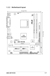
- a8v vm se layout
- a8v vm se manual
- a8v vm se memory
- a8v vm se micro atx
- a8v vm se motherboard
- a8v vm se motherboard driver
- a8v vm se motherboard driver download
- a8v vm se motherboard drivers
- a8v vm se motherboard manual
- a8v vm se overclocking
- a8v vm se problems
- a8v vm se socket 939
- a8v vm se sound driver
- a8v vm se sound driver download
- a8v vm se sound drivers
- a8v vm se specifications
- a8v vm se support cd
- a8v vm se vga
- a8v vm se vga drivers
- a8v vm se vga drivers for windows 7
- a8v vm se video driver
- a8v vm se vista drivers
- a8v vm se windows 7
- a8v vm socket 939 motherboard
- a8v-vm se
- a8v-vm se 939
- a8v-vm se asus
- a8v-vm se asus manual
- a8v-vm se audio
- a8v-vm se audio driver
- a8v-vm se audio driver download
- a8v-vm se audio driver for windows 7
- a8v-vm se audio drivers
- a8v-vm se audio drivers for windows 7
- a8v-vm se audio drivers windows 7
- a8v-vm se audio windows 7
- a8v-vm se bios
- a8v-vm se bios update
- a8v-vm se cannot see ide
- a8v-vm se cpu support
- a8v-vm se display drivers
- a8v-vm se driver download
- a8v-vm se drivers
- a8v-vm se drivers download
- a8v-vm se drivers for windows 7
- a8v-vm se drivers for windows 7 sound
- a8v-vm se drivers for windows xp
- a8v-vm se drivers windows 7
- a8v-vm se drivers xp
- a8v-vm se front audio connectors
- a8v-vm se k8m890
- a8v-vm se manual
- a8v-vm se memory
- a8v-vm se micro atx
- a8v-vm se motherboard
- a8v-vm se motherboard driver
- a8v-vm se motherboard drivers
- a8v-vm se motherboard drivers download
- a8v-vm se motherboard drivers free download
- a8v-vm se motherboard manual
- a8v-vm se overclocking
- a8v-vm se processor support
- a8v-vm se ram
- a8v-vm se realtek audio drivers
- a8v-vm se socket 939
- a8v-vm se sound driver
- a8v-vm se sound driver windows 7
- a8v-vm se sound drivers
- a8v-vm se sound drivers for windows 7
- a8v-vm se specifications
- a8v-vm se support
- a8v-vm se vga driver download
- a8v-vm se video windows 7
- a8v-vm se windows 7
- a8v-vm se windows 7 audio
- a8v-vm se windows 7 audio driver
- a8v-vm se windows 7 drivers
- a8v-vm series
- a8vvm se drivers
- a8vvm se la vi
- a8vvm search
- a8vvmse
- a8vvmse asus
- a8vvmse rom
- a8vvmse.rom
- asus a8v vm se
- asus a8v vm se 939
- asus a8v vm se audio driver
- asus a8v vm se bios
- asus a8v vm se display driver
- asus a8v vm se drivers
- asus a8v vm se drivers for windows 7
- asus a8v vm se drivers motherboard driver
- asus a8v vm se dual core
- asus a8v vm se green
- asus a8v vm se k8m890
- asus a8v vm se layout
- asus a8v vm se manual
- asus a8v vm se micro atx
- asus a8v vm se motherboard
- asus a8v vm se motherboard driver download
- asus a8v vm se motherboard drivers
- asus a8v vm se motherboard manual
- asus a8v vm se overclocking
- asus a8v vm se problems
- asus a8v vm se socket 939
- asus a8v vm se sound driver
- asus a8v vm se specifications
- asus a8v vm se vga
- asus a8v vm se vga drivers
- asus a8v vm se vga drivers for windows 7
- asus a8v vm socket 939 motherboard
- asus a8v-vm se
- asus a8v-vm se 939
- asus a8v-vm se audio driver
- asus a8v-vm se audio driver download
- asus a8v-vm se audio driver for windows 7
- asus a8v-vm se audio drivers
- asus a8v-vm se audio drivers for windows 7
- asus a8v-vm se bios
- asus a8v-vm se bios update
- asus a8v-vm se cannot see ide
- asus a8v-vm se cpu support
- asus a8v-vm se display drivers
- asus a8v-vm se driver download
- asus a8v-vm se drivers
- asus a8v-vm se drivers download
- asus a8v-vm se drivers for windows 7
- asus a8v-vm se drivers for windows 7 sound
- asus a8v-vm se drivers for windows xp
- asus a8v-vm se front audio connectors
- asus a8v-vm se k8m890
- asus a8v-vm se manual
- asus a8v-vm se memory
- asus a8v-vm se micro atx
- asus a8v-vm se motherboard
- asus a8v-vm se motherboard driver
- asus a8v-vm se motherboard drivers
- asus a8v-vm se motherboard drivers download
- asus a8v-vm se motherboard drivers free download
- asus a8v-vm se motherboard manual
- asus a8v-vm se realtek audio drivers
- asus a8v-vm se socket 939
- asus a8v-vm se sound driver
- asus a8v-vm se sound driver windows 7
- asus a8v-vm se sound drivers for windows 7
- asus a8v-vm se specifications
- asus a8v-vm se vga driver download
- asus a8v-vm se video windows 7
- asus a8v-vm se windows 7
- asus a8v-vm se windows 7 audio
- asus a8v-vm se windows 7 audio driver
- asus a8v-vm se windows 7 drivers
- asus a8vvmse
- asus motherboard a8v-vm se driver download
- driver a8v-vm se
- driver asus a8v-vm se
- motherboard a8v-vm se driver download