
A8V-E SE User's Manual for English Edition
Page 5
Contents 2.4.5 Chipset 2-22 2.4.6 PCI PnP 2-25 2.4.7 Onboard Devices Configuration 2-27 2.4.8 USB Configuration 2-28 2.5 Power menu 2-29 2.5.1 ACPI Suspend Type 2-29 2.5.2 ACPI APIC Support 2-29 2.5.3 APM Configuration 2-30 2.5.4 Hardware Monitor 2-32 2.6 Boot menu 2-33 2.6.1 Boot Device Priority 2-34 2.6.2 Removable ...2-35 2.6.6 Security 2-37 2.7 Exit menu 2-38 Chapter 3: Software support 3.1 Installing an operating system 3-2 3.2 Support CD information 3-2 3.2.1 Running the support CD 3-2 3.2.2 Drivers menu 3-3 3.2.3 Utilities menu 3-4 3.2.4 ASUS Contact information 3-5 v
Contents 2.4.5 Chipset 2-22 2.4.6 PCI PnP 2-25 2.4.7 Onboard Devices Configuration 2-27 2.4.8 USB Configuration 2-28 2.5 Power menu 2-29 2.5.1 ACPI Suspend Type 2-29 2.5.2 ACPI APIC Support 2-29 2.5.3 APM Configuration 2-30 2.5.4 Hardware Monitor 2-32 2.6 Boot menu 2-33 2.6.1 Boot Device Priority 2-34 2.6.2 Removable ...2-35 2.6.6 Security 2-37 2.7 Exit menu 2-38 Chapter 3: Software support 3.1 Installing an operating system 3-2 3.2 Support CD information 3-2 3.2.1 Running the support CD 3-2 3.2.2 Drivers menu 3-3 3.2.3 Utilities menu 3-4 3.2.4 ASUS Contact information 3-5 v

A8V-E SE User's Manual for English Edition
Page 7
...temperature extremes. Do not place the product in your area. These devices could interrupt the grounding circuit. • Make sure that the power cables for the devices are unplugged before using an adapter or extension cord. Operation safety • Before installing the motherboard and adding devices... on a stable surface. • If you are using the product, make sure all cables are correctly connected and the power cables are not sure about the voltage of the electrical outlet you encounter technical problems with the package. • Before using , contact...
...temperature extremes. Do not place the product in your area. These devices could interrupt the grounding circuit. • Make sure that the power cables for the devices are unplugged before using an adapter or extension cord. Operation safety • Before installing the motherboard and adding devices... on a stable surface. • If you are using the product, make sure all cables are correctly connected and the power cables are not sure about the voltage of the electrical outlet you encounter technical problems with the package. • Before using , contact...
A8V-E SE User's Manual for English Edition
Page 11
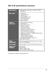
xi A8V-E SE specifications summary BIOS features Rear panel Internal connectors Power Requirement Form Factor Support CD contents 4 MB Flash ROM, Award BIOS, PnP, DMI2.0, WfM2.0, SM BIOS 2.3 1 x Parallel port 1 x LAN (RJ-45) port 4 x USB 2.0 ports 1 x Coaxial... audio connector 1 x Internal audio (CD/AUX) connectors System panel connector ATX power supply (with 24-pin and 4-pin 12 V plugs) ATX 12 V 2.0 compliant ATX form factor: 12 in x 9.6 in (30.5 cm x 24.4 cm) Device drivers ASUS PC Probe ASUS Live Update Utility Antivirus software (OEM version) *Specifications are subject to change without...
xi A8V-E SE specifications summary BIOS features Rear panel Internal connectors Power Requirement Form Factor Support CD contents 4 MB Flash ROM, Award BIOS, PnP, DMI2.0, WfM2.0, SM BIOS 2.3 1 x Parallel port 1 x LAN (RJ-45) port 4 x USB 2.0 ports 1 x Coaxial... audio connector 1 x Internal audio (CD/AUX) connectors System panel connector ATX power supply (with 24-pin and 4-pin 12 V plugs) ATX 12 V 2.0 compliant ATX form factor: 12 in x 9.6 in (30.5 cm x 24.4 cm) Device drivers ASUS PC Probe ASUS Live Update Utility Antivirus software (OEM version) *Specifications are subject to change without...

A8V-E SE User's Manual for English Edition
Page 14
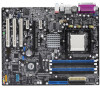
Before you for the following items. Motherboard ASUS A8V-E SE motherboard Cables 2 x Serial ATA signal cables 2 x Serial ATA power cables 1 x Ultra DMA/133 cables 1 x 40-conductor IDE cable 1 x Floppy disk drive cable Accessories I/O shield A p p l i c a t i o n C D s ASUS motherboard support CD D o c u m e n t a t i o n User guide If any of ASUS quality motherboards! The motherboard delivers a host of new ...devices on it another standout in your package with the list below. 1.2 Package contents Check your motherboard package for buying an ASUS® A8V-E SE motherboard!
Before you for the following items. Motherboard ASUS A8V-E SE motherboard Cables 2 x Serial ATA signal cables 2 x Serial ATA power cables 1 x Ultra DMA/133 cables 1 x 40-conductor IDE cable 1 x Floppy disk drive cable Accessories I/O shield A p p l i c a t i o n C D s ASUS motherboard support CD D o c u m e n t a t i o n User guide If any of ASUS quality motherboards! The motherboard delivers a host of new ...devices on it another standout in your package with the list below. 1.2 Package contents Check your motherboard package for buying an ASUS® A8V-E SE motherboard!
A8V-E SE User's Manual for English Edition
Page 15
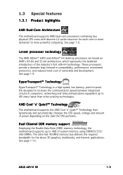
See page 1-9. See page 1-13. ASUS A8V-E SE 1-3 See page 1-9. These processors provide a dramatic leap forward in computers, networking and telecommunicatons equipment up to 4GB of power depending on AMD's 64-bit and 32-bit architecture, which represents the landmark introduction of ownership and development. AMD Cool 'n' Quiet!™ Technology The motherboard ...'s first x86-64 technology. HyperTransport™ Technology HyperTransport™ Technology is a high-speed, low latency, point-to-point link designed to meet demands for more powerful computing.
See page 1-9. See page 1-13. ASUS A8V-E SE 1-3 See page 1-9. These processors provide a dramatic leap forward in computers, networking and telecommunicatons equipment up to 4GB of power depending on AMD's 64-bit and 32-bit architecture, which represents the landmark introduction of ownership and development. AMD Cool 'n' Quiet!™ Technology The motherboard ...'s first x86-64 technology. HyperTransport™ Technology HyperTransport™ Technology is a high-speed, low latency, point-to-point link designed to meet demands for more powerful computing.

A8V-E SE User's Manual for English Edition
Page 16
... levels to 150 MB/s data transfer rate. Serial ATA technology The motherboard supports Serial ATA technology through the onboard ALC850 CODEC with digital connectivity to powerful audio and speaker systems. See page 1-23 for details. This high speed interface is backward compatible with existing PCI specifications. The S/PDIF technology turns your...
... levels to 150 MB/s data transfer rate. Serial ATA technology The motherboard supports Serial ATA technology through the onboard ALC850 CODEC with digital connectivity to powerful audio and speaker systems. See page 1-23 for details. This high speed interface is backward compatible with existing PCI specifications. The S/PDIF technology turns your...

A8V-E SE User's Manual for English Edition
Page 18
...e p o w e r s u p p l y . 1.4 Before you proceed Take note of the following precautions before you install motherboard components or change any motherboard settings. • Unplug the power cord from the wall socket before touching any component. • Use a grounded wrist strap or touch a safely grounded object or to a metal object, such as...power LED that lights up to the motherboard, peripherals, and/or components. Failure to do so may cause severe damage to indicate that the system is switched off mode. A8V-E SE ® A8V-E SE Onboard LED SB_PWR ON Standby Power OFF Powered...
...e p o w e r s u p p l y . 1.4 Before you proceed Take note of the following precautions before you install motherboard components or change any motherboard settings. • Unplug the power cord from the wall socket before touching any component. • Use a grounded wrist strap or touch a safely grounded object or to a metal object, such as...power LED that lights up to the motherboard, peripherals, and/or components. Failure to do so may cause severe damage to indicate that the system is switched off mode. A8V-E SE ® A8V-E SE Onboard LED SB_PWR ON Standby Power OFF Powered...

A8V-E SE User's Manual for English Edition
Page 19
... the rear of the chassis A8V-E SE ® ASUS A8V-E SE 1-7 Failure to the chassis. The edge with external ports goes to the rear part of the chassis as indicated in the correct orientation. 1.5 Motherboard overview Before you install the motherboard, study the configuration of your chassis to unplug the power cord before installing or removing...
... the rear of the chassis A8V-E SE ® ASUS A8V-E SE 1-7 Failure to the chassis. The edge with external ports goes to the rear part of the chassis as indicated in the correct orientation. 1.5 Motherboard overview Before you install the motherboard, study the configuration of your chassis to unplug the power cord before installing or removing...

A8V-E SE User's Manual for English Edition
Page 27
...-5 Winbond W9451GCDB-5 KINGMAX MPXB62D-38KT3R KINGMAX MPXC22D-38KT3R ATP AG64L64T8SQC4S ATP AG28L64T8SMC4M NANYA NT256D64S88C0G-5T NANYA NT512D64S8HC0G-5T BRAIN POWER B6U808-256M-SAM-400 ProMOS V826632K24SCTG-D0 ProMOS V826664K24SCTG-D0 Deutron A8C53T-5B1T Deutron AL6D8C53T-5B1T Novax 96M425653CE-40TB6 Novax 96M451253CE... slots as two pairs of Dual-channel memory configuration. Double Sided DIMM Support: A - ASUS A8V-E SE 1-15 supports on pair of modules inserted into either slot, in a Single-channel memory configuration. Single Sided D S -
...-5 Winbond W9451GCDB-5 KINGMAX MPXB62D-38KT3R KINGMAX MPXC22D-38KT3R ATP AG64L64T8SQC4S ATP AG28L64T8SMC4M NANYA NT256D64S88C0G-5T NANYA NT512D64S8HC0G-5T BRAIN POWER B6U808-256M-SAM-400 ProMOS V826632K24SCTG-D0 ProMOS V826664K24SCTG-D0 Deutron A8C53T-5B1T Deutron AL6D8C53T-5B1T Novax 96M425653CE-40TB6 Novax 96M451253CE... slots as two pairs of Dual-channel memory configuration. Double Sided DIMM Support: A - ASUS A8V-E SE 1-15 supports on pair of modules inserted into either slot, in a Single-channel memory configuration. Single Sided D S -

A8V-E SE User's Manual for English Edition
Page 28
... is properly seated. Simultaneously press the retaining clips outward to avoid damaging the DIMM. 3 3. Locked Retaining Clip 1.7.4 Removing a DIMM Follow these steps to unplug the power supply before adding or removing DIMMs or other system components. 1.7.3 Installing a DIMM Make sure to remove a DIMM. 2 1. Failure to do so may cause severe damage...
... is properly seated. Simultaneously press the retaining clips outward to avoid damaging the DIMM. 3 3. Locked Retaining Clip 1.7.4 Removing a DIMM Follow these steps to unplug the power supply before adding or removing DIMMs or other system components. 1.7.3 Installing a DIMM Make sure to remove a DIMM. 2 1. Failure to do so may cause severe damage...
A8V-E SE User's Manual for English Edition
Page 29
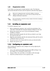
... until the card is already installed in a chassis). 3. Secure the card to use . 4. Install the software drivers for information on the slot. 5. ASUS A8V-E SE 1-17 We recommended to unplug the power cord before installing a PCI Express x16 card. 1.8.1 Installing an expansion card To install an expansion card: 1. Turn on the next page. 3. See...
... until the card is already installed in a chassis). 3. Secure the card to use . 4. Install the software drivers for information on the slot. 5. ASUS A8V-E SE 1-17 We recommended to unplug the power cord before installing a PCI Express x16 card. 1.8.1 Installing an expansion card To install an expansion card: 1. Turn on the next page. 3. See...
A8V-E SE User's Manual for English Edition
Page 32
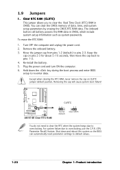
... CMOS, which include system setup information such as system passwords. To erase the RTC RAM: 1. Re-install the battery. 5. The onboard button cell battery powers the RAM data in CMOS. Hold down and reboot the system so the BIOS can clear the CMOS memory of date, time, and system setup... the cap on pins 2-3 for about 5~10 seconds, then move the cap back to overclocking. Turn OFF the computer and unplug the power cord. 2. 1.9 Jumpers 1. A8V-E SE ® A8V-E SE Clear RTC RAM CLRTC 12 23 Normal (Default) Clear CMOS You do not need to clear the RTC when the system hangs due to...
... CMOS, which include system setup information such as system passwords. To erase the RTC RAM: 1. Re-install the battery. 5. The onboard button cell battery powers the RAM data in CMOS. Hold down and reboot the system so the BIOS can clear the CMOS memory of date, time, and system setup... the cap on pins 2-3 for about 5~10 seconds, then move the cap back to overclocking. Turn OFF the computer and unplug the power cord. 2. 1.9 Jumpers 1. A8V-E SE ® A8V-E SE Clear RTC RAM CLRTC 12 23 Normal (Default) Clear CMOS You do not need to clear the RTC when the system hangs due to...

A8V-E SE User's Manual for English Edition
Page 33
... when you to wake up . • The total current consumed must NOT exceed the power supply capability (+5VSB) whether under normal condition or in the BIOS. A8V-E SE KBPWR 2 1 +5V (Default) 2 1 +5VSB ® A8V-E SE Keyboard power setting ASUS A8V-E SE 1-21 Refer of the Keyboard power (3-pin KBPWR) This jumper allows you press a key on the keyboard (the default...
... when you to wake up . • The total current consumed must NOT exceed the power supply capability (+5VSB) whether under normal condition or in the BIOS. A8V-E SE KBPWR 2 1 +5V (Default) 2 1 +5VSB ® A8V-E SE Keyboard power setting ASUS A8V-E SE 1-21 Refer of the Keyboard power (3-pin KBPWR) This jumper allows you press a key on the keyboard (the default...

A8V-E SE User's Manual for English Edition
Page 38
...and Power fan connectors (3-pin CPU_FAN, 3-pin CHA_FAN1, 3-pin PWR_FAN) The fan connectors support cooling fans of 350mA~2000mA (24 W max.) or a total of sufficient air flow inside the system may damage the motherboard components. CPU_FAN Rotation +12V GND Rotation +12V GND A8V-E SE ® A8V-E SE Fan...These are not jumpers! Right Audio Channel Ground Ground Left Audio Channel Right Audio Channel Ground Ground Left Audio Channel A8V-E SE ® AUX CD A8V-E SE Internal audio connectors 1-26 Chapter 1: Product introduction DO NOT place jumper caps on the motherboard, making sure that ...
...and Power fan connectors (3-pin CPU_FAN, 3-pin CHA_FAN1, 3-pin PWR_FAN) The fan connectors support cooling fans of 350mA~2000mA (24 W max.) or a total of sufficient air flow inside the system may damage the motherboard components. CPU_FAN Rotation +12V GND Rotation +12V GND A8V-E SE ® A8V-E SE Fan...These are not jumpers! Right Audio Channel Ground Ground Left Audio Channel Right Audio Channel Ground Ground Left Audio Channel A8V-E SE ® AUX CD A8V-E SE Internal audio connectors 1-26 Chapter 1: Product introduction DO NOT place jumper caps on the motherboard, making sure that ...

A8V-E SE User's Manual for English Edition
Page 40
... are designed to install additional devices. EATXPWR +3 Volts -12 Volts ATX12V Ground PSON# A8V-E SE GND +12V DC GND Ground +12V DC Ground Ground -5 Volts ® +5 Volts +5 Volts A8V-E SE ATX power connectors +5 Volts Ground +3 Volts +3 Volts Ground +5 Volts Ground +5 Volts Ground Power OK +5V Standby +12 Volts +12 Volts +3 Volts 1-28 Chapter 1: Product introduction 9 . otherwise...
... are designed to install additional devices. EATXPWR +3 Volts -12 Volts ATX12V Ground PSON# A8V-E SE GND +12V DC GND Ground +12V DC Ground Ground -5 Volts ® +5 Volts +5 Volts A8V-E SE ATX power connectors +5 Volts Ground +3 Volts +3 Volts Ground +5 Volts Ground +5 Volts Ground Power OK +5V Standby +12 Volts +12 Volts +3 Volts 1-28 Chapter 1: Product introduction 9 . otherwise...
A8V-E SE User's Manual for English Edition
Page 42
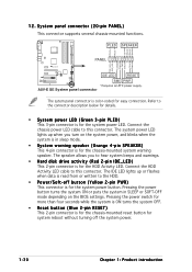
... Chapter 1: Product introduction PLED SPEAKER PLED+ PLED+5V Ground Ground Speaker A8V-E SE PANEL IDE_LED+ IDE_LED- A8V-E SE System panel connector The sytem panel connector is for the chassis-mounted reset button for the system power LED. Pressing the power switch for more than four seconds while the system is ON turns the system OFF. •...
... Chapter 1: Product introduction PLED SPEAKER PLED+ PLED+5V Ground Ground Speaker A8V-E SE PANEL IDE_LED+ IDE_LED- A8V-E SE System panel connector The sytem panel connector is for the chassis-mounted reset button for the system power LED. Pressing the power switch for more than four seconds while the system is ON turns the system OFF. •...
A8V-E SE User's Manual for English Edition
Page 46
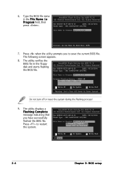
... Complete AwardBIOS Flash Utility for ASUS V1.01 (C) Phoenix Technologies Ltd. File Name to Program: A8V-E_SE.BIN Flashing Complete Press to Program: A8V-E_SE.BIN Progr111a222m333444555F666l777a888s999000h111i222n333g444555666M777e888m999o000111r222y333444-555666777O888F999E00001110 OK 111122223333... Write OK 111122223333 No Update 111122223333 Write Fail Warning: Don't Turn Off Power ...
... Complete AwardBIOS Flash Utility for ASUS V1.01 (C) Phoenix Technologies Ltd. File Name to Program: A8V-E_SE.BIN Flashing Complete Press to Program: A8V-E_SE.BIN Progr111a222m333444555F666l777a888s999000h111i222n333g444555666M777e888m999o000111r222y333444-555666777O888F999E00001110 OK 111122223333... Write OK 111122223333 No Update 111122223333 Write Fail Warning: Don't Turn Off Power ...

A8V-E SE User's Manual for English Edition
Page 50
Save the BIOS file to continue POST 4. The following . Press + during the Power-On Self Tests (POST). AwardBIOS Flash Utility for the motherboard. 2. When the correct BIOS file is accessible by pressing + during POST to display the following ... built-in the BIOS chip so it is found, EZ Flash performs the BIOS update process and automatically reboots the system when done. 2.1.5 ASUS EZ Flash utility The ASUS EZ Flash feature allows you to update the BIOS without having to go through the long process of booting from a floppy disk and...
Save the BIOS file to continue POST 4. The following . Press + during the Power-On Self Tests (POST). AwardBIOS Flash Utility for the motherboard. 2. When the correct BIOS file is accessible by pressing + during POST to display the following ... built-in the BIOS chip so it is found, EZ Flash performs the BIOS update process and automatically reboots the system when done. 2.1.5 ASUS EZ Flash utility The ASUS EZ Flash feature allows you to update the BIOS without having to go through the long process of booting from a floppy disk and...

A8V-E SE User's Manual for English Edition
Page 54
... Exit Menu. See section "4.7 Exit Menu." • The BIOS setup screens shown in section "4.1 Managing and updating your screen. • Visit the ASUS website (www.asus.com) to "Run Setup". 2.2 BIOS setup program This motherboard supports a programmable Low-Pin Count (LPC) chip that the computer can recognize these changes... of the LPC chip. Even if you are for this last option only if the first two failed. You can change the power management settings. This requires you can also restart by pressing the reset button on the motherboard stores the Setup utility. Press during the...
... Exit Menu. See section "4.7 Exit Menu." • The BIOS setup screens shown in section "4.1 Managing and updating your screen. • Visit the ASUS website (www.asus.com) to "Run Setup". 2.2 BIOS setup program This motherboard supports a programmable Low-Pin Count (LPC) chip that the computer can recognize these changes... of the LPC chip. Even if you are for this last option only if the first two failed. You can change the power management settings. This requires you can also restart by pressing the reset button on the motherboard stores the Setup utility. Press during the...
A8V-E SE User's Manual for English Edition
Page 55
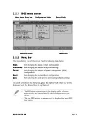
ASUS A8V-E SE 2-13 Installed Memory 256MB F1:Help ESC: Exit ↑↓ : Select Item →←: Select Menu -/+: Change Value Enter: Select Sub-menu F5: Setup Defaults ... bar The menu bar on top of the screen has the following main items: Main Advanced Power Boot Exit For changing the basic system configuration For changing the advanced system settings For changing the advanced power management (APM) configuration For changing the system boot configuration For selecting the exit options and loading...
ASUS A8V-E SE 2-13 Installed Memory 256MB F1:Help ESC: Exit ↑↓ : Select Item →←: Select Menu -/+: Change Value Enter: Select Sub-menu F5: Setup Defaults ... bar The menu bar on top of the screen has the following main items: Main Advanced Power Boot Exit For changing the basic system configuration For changing the advanced system settings For changing the advanced power management (APM) configuration For changing the system boot configuration For selecting the exit options and loading...


