
K8 series Quick Setup Guide
Page 10
...calling for the memory Qualified Vendors List (QVL). • Check the floppy drive configuration in the BIOS setup. • Check the floppy drive cable, make sure it is inserted properly in the BIOS setup. • Check the IDE drive cables, make sure they are corrected properly. • Make... sure that the device drivers are installed. • Enter BIOS setup and load default settings. • Make sure that the power cable is connected properly to the default value, press and select Yes. ...
...calling for the memory Qualified Vendors List (QVL). • Check the floppy drive configuration in the BIOS setup. • Check the floppy drive cable, make sure it is inserted properly in the BIOS setup. • Check the IDE drive cables, make sure they are corrected properly. • Make... sure that the device drivers are installed. • Enter BIOS setup and load default settings. • Make sure that the power cable is connected properly to the default value, press and select Yes. ...

A8V Deluxe User's Manual
Page 4
... Reporter 3-3 3.3.1 Vocal POST messages 3-3 3.3.2 Winbond Voice Editor 3-5 Chapter 4: BIOS setup 4.1 Managing and updating your BIOS 4-1 4.1.1 Creating a bootable floppy disk 4-1 4.1.2 Using AFUDOS to update the BIOS 4-2 4.1.3 Using AFUDOS to copy BIOS from PC 4-3 4.1.4 Using ASUS EZ Flash to update the BIOS 4-4 4.1.5 Recovering the BIOS with CrashFree BIOS 2 ....... 4-5 4.1.6 ASUS Update 4-7 4.2 BIOS Setup program 4-9 4.2.1 BIOS menu screen 4-10 4.2.2 Menu bar 4-10 4.2.3 Navigation keys 4-10...
... Reporter 3-3 3.3.1 Vocal POST messages 3-3 3.3.2 Winbond Voice Editor 3-5 Chapter 4: BIOS setup 4.1 Managing and updating your BIOS 4-1 4.1.1 Creating a bootable floppy disk 4-1 4.1.2 Using AFUDOS to update the BIOS 4-2 4.1.3 Using AFUDOS to copy BIOS from PC 4-3 4.1.4 Using ASUS EZ Flash to update the BIOS 4-4 4.1.5 Recovering the BIOS with CrashFree BIOS 2 ....... 4-5 4.1.6 ASUS Update 4-7 4.2 BIOS Setup program 4-9 4.2.1 BIOS menu screen 4-10 4.2.2 Menu bar 4-10 4.2.3 Navigation keys 4-10...

A8V Deluxe User's Manual
Page 9
... • Chapter 2: Hardware information This chapter lists the hardware setup procedures that you need when installing the motherboard. ASUS websites The ASUS website provides updated information on the motherboard. • Chapter 3: Powering up This chapter describes the power up sequence, ...information Refer to perform when installing system components. Refer to change system settings through the BIOS Setup menus. It includes description of the jumpers and connectors on ASUS hardware and software products. These documents are also provided. • Chapter 5: Software ...
... • Chapter 2: Hardware information This chapter lists the hardware setup procedures that you need when installing the motherboard. ASUS websites The ASUS website provides updated information on the motherboard. • Chapter 3: Powering up This chapter describes the power up sequence, ...information Refer to perform when installing system components. Refer to change system settings through the BIOS Setup menus. It includes description of the jumpers and connectors on ASUS hardware and software products. These documents are also provided. • Chapter 5: Software ...
A8V Deluxe User's Manual
Page 11
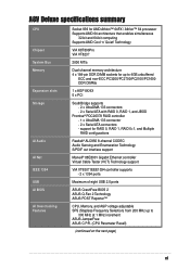
...VCT) Technology support VIA VT6307 IEEE1394 controller supports - 2 x 1394 ports Maximum of eight USB 2.0 ports ÅSUS CrashFree BIOS 2 ASUS Q-Fan 2 Technology ASUS POST Reporter™ CPU, Memory, and AGP voltage adjustable SFS (Stepless Frequency Selection) from 200 MHz up to 300 MHz ...PDC20378 RAID controller - 1 x UltraDMA 133 connector - 2 x Serial ATA connectors - A8V Deluxe specifications summary CPU Chipset System Bus Memory Expansion slots Storage AI Audio AI Net IEEE 1394 USB AI BIOS AI Overclocking Features Socket 939 for AMD Athlon™ 64FX / Athlon™ 64 processor ...
...VCT) Technology support VIA VT6307 IEEE1394 controller supports - 2 x 1394 ports Maximum of eight USB 2.0 ports ÅSUS CrashFree BIOS 2 ASUS Q-Fan 2 Technology ASUS POST Reporter™ CPU, Memory, and AGP voltage adjustable SFS (Stepless Frequency Selection) from 200 MHz up to 300 MHz ...PDC20378 RAID controller - 1 x UltraDMA 133 connector - 2 x Serial ATA connectors - A8V Deluxe specifications summary CPU Chipset System Bus Memory Expansion slots Storage AI Audio AI Net IEEE 1394 USB AI BIOS AI Overclocking Features Socket 939 for AMD Athlon™ 64FX / Athlon™ 64 processor ...
A8V Deluxe User's Manual
Page 12
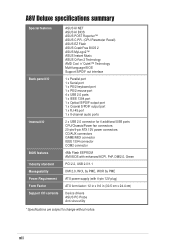
...A8V Deluxe specifications summary Special features Back panel I/O Internal I/O BIOS features Industry standard Manageability Power Requirement Form Factor Support CD contents ASUS AI NET ASUS AI BIOS ASUS POST Reporter™ ASUS C.P.R. (CPU Parameter Recall) ASUS EZ Flash ASUS CrashFree BIOS 2 ASUS MyLogo2™ ASUS Instant Music ASUS Q-Fan 2 Technology AMD Cool 'n' Quiet!™ Technology Multi-language BIOS... CD/AUX connectors GAME/MIDI connector IEEE 1394 connector COM2 connector 4Mb Flash EEPROM AMI BIOS with enhanced ACPI, PnP, DMI2.0, Green PCI 2.2, USB 2.0/1.1 DMI 2.0, WOL by...
...A8V Deluxe specifications summary Special features Back panel I/O Internal I/O BIOS features Industry standard Manageability Power Requirement Form Factor Support CD contents ASUS AI NET ASUS AI BIOS ASUS POST Reporter™ ASUS C.P.R. (CPU Parameter Recall) ASUS EZ Flash ASUS CrashFree BIOS 2 ASUS MyLogo2™ ASUS Instant Music ASUS Q-Fan 2 Technology AMD Cool 'n' Quiet!™ Technology Multi-language BIOS... CD/AUX connectors GAME/MIDI connector IEEE 1394 connector COM2 connector 4Mb Flash EEPROM AMI BIOS with enhanced ACPI, PnP, DMI2.0, Green PCI 2.2, USB 2.0/1.1 DMI 2.0, WOL by...

A8V Deluxe User's Manual
Page 18
... Tester™ (VCT) net-diagnosing utility that intelligently diagnoses and reports cable faults from the ASUS support CD in case when the BIOS codes and data are corrupted. See page 4-5. 1-4 Chapter 1: Product introduction The controller is a combination of three... ASUS intelligent solutions: Q-Fan 2, POST Reporter™, and CrashFree BIOS 2. 1.3.2 Unique ASUS features AI NET solution The Marvell® Gigabit LAN controller chipset is onboard to provide a single-chip...
... Tester™ (VCT) net-diagnosing utility that intelligently diagnoses and reports cable faults from the ASUS support CD in case when the BIOS codes and data are corrupted. See page 4-5. 1-4 Chapter 1: Product introduction The controller is a combination of three... ASUS intelligent solutions: Q-Fan 2, POST Reporter™, and CrashFree BIOS 2. 1.3.2 Unique ASUS features AI NET solution The Marvell® Gigabit LAN controller chipset is onboard to provide a single-chip...

A8V Deluxe User's Manual
Page 19
... of your system with customizable boot logos. ASUS EZ Flash BIOS With the ASUS EZ Flash, you to open the system chassis and clear the RTC data. The localized BIOS menus allow you can easily update the system BIOS even before loading the operating system. See pages...ASUS Multi-language BIOS The multi-language BIOS allows you to use a DOS-based utility or boot from the available options. See pages 3-3, 4-29 AI Overclocking This feature allows convenient overclocking up to 30% (depending on the installed CPU and DRAM) to select the language of boot errors, if any. ASUS A8V Deluxe...
... of your system with customizable boot logos. ASUS EZ Flash BIOS With the ASUS EZ Flash, you to open the system chassis and clear the RTC data. The localized BIOS menus allow you can easily update the system BIOS even before loading the operating system. See pages...ASUS Multi-language BIOS The multi-language BIOS allows you to use a DOS-based utility or boot from the available options. See pages 3-3, 4-29 AI Overclocking This feature allows convenient overclocking up to 30% (depending on the installed CPU and DRAM) to select the language of boot errors, if any. ASUS A8V Deluxe...

A8V Deluxe User's Manual
Page 25
ASUS A8V Deluxe motherboard 2-3 2.2.3 Motherboard layout PS/2KBMS T: Mouse B: Keyboard KBPWR ...Graphics Port (AGP) PRI_IDE Marvell Gigabit LAN CD Realtek ALC850 AUX FP_AUDIO PCI1 PCI2 PCI3 PCI4 A8V PCI5 FLOPPY ® CR2032 3V Lithium Cell CMOS Power VIA VT8237 PRI_RAID SATA2 SATA1 CHA_FAN ...Promise 20378 SATA_RAID2 SATA_RAID1 USB78 CLRTC USBPWR56 USBPWR78 USB56 CHASSIS Super I/O GAME 4Mbit BIOS SB_PWR PANEL COM2 SEC_IDE 30.5cm (12.0in) KBPWR 12 23 +5V +5VSB (Default) USBPWR12 2 1 +5V (Default) ...
ASUS A8V Deluxe motherboard 2-3 2.2.3 Motherboard layout PS/2KBMS T: Mouse B: Keyboard KBPWR ...Graphics Port (AGP) PRI_IDE Marvell Gigabit LAN CD Realtek ALC850 AUX FP_AUDIO PCI1 PCI2 PCI3 PCI4 A8V PCI5 FLOPPY ® CR2032 3V Lithium Cell CMOS Power VIA VT8237 PRI_RAID SATA2 SATA1 CHA_FAN ...Promise 20378 SATA_RAID2 SATA_RAID1 USB78 CLRTC USBPWR56 USBPWR78 USB56 CHASSIS Super I/O GAME 4Mbit BIOS SB_PWR PANEL COM2 SEC_IDE 30.5cm (12.0in) KBPWR 12 23 +5V +5VSB (Default) USBPWR12 2 1 +5V (Default) ...
A8V Deluxe User's Manual
Page 37
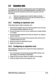
... that they support. Secure the card to unplug the power cord before adding or removing expansion cards. Assign an IRQ to the card. ASUS A8V Deluxe motherboard 2-15 Keep the screw for the expansion card. See Chapter 4 for the card. 2. The following sub-sections describe the slots ...is already installed in a chassis). 3. Refer to the tables on the system and change the necessary BIOS settings, if any. Remove the system unit cover (if your motherboard is completely seated on BIOS setup. 2. Install the software drivers for later use . 2.5 Expansion slots In the future, you...
... that they support. Secure the card to unplug the power cord before adding or removing expansion cards. Assign an IRQ to the card. ASUS A8V Deluxe motherboard 2-15 Keep the screw for the expansion card. See Chapter 4 for the card. 2. The following sub-sections describe the slots ...is already installed in a chassis). 3. Refer to the tables on the system and change the necessary BIOS settings, if any. Remove the system unit cover (if your motherboard is completely seated on BIOS setup. 2. Install the software drivers for later use . 2.5 Expansion slots In the future, you...

A8V Deluxe User's Manual
Page 40
... cord. 2. Move the jumper from pins 1-2 (default) to overclocking, use the C.P.R. (CPU Parameter Recall) feature. Hold down and reboot the system so the BIOS can clear the CMOS memory of date, time, and system setup parameters by the onboard button cell battery. Shut down the key during the boot...values. 2-18 Chapter 2: Hardware information Clear RTC RAM (CLRTC) This jumper allows you to clear the Real Time Clock (RTC) RAM in data. ® A8V A8V Deluxe Clear RTC RAM CLRTC 12 23 Normal (Default) Clear CMOS You do not need to cleat the RTC when the system hands due to pins...
... cord. 2. Move the jumper from pins 1-2 (default) to overclocking, use the C.P.R. (CPU Parameter Recall) feature. Hold down and reboot the system so the BIOS can clear the CMOS memory of date, time, and system setup parameters by the onboard button cell battery. Shut down the key during the boot...values. 2-18 Chapter 2: Hardware information Clear RTC RAM (CLRTC) This jumper allows you to clear the Real Time Clock (RTC) RAM in data. ® A8V A8V Deluxe Clear RTC RAM CLRTC 12 23 Normal (Default) Clear CMOS You do not need to cleat the RTC when the system hands due to pins...

A8V Deluxe User's Manual
Page 41
...requires a power supply that can provide 500mA on the +5VSB lead, and a corresponding setting in low power mode) using the connected USB devices. ASUS A8V Deluxe motherboard 2-19 Otherwise, the system would not power up the computer from S3 and S4 sleep modes (no power to pins 2-3 (+5VSB) if you...disable the keyboard wake-up the computer when you wish to wake up from S1 sleep mode (CPU stopped, DRAM refreshed, system running in the BIOS (See section "4.5.5 APM Configuration"). Set to +5VSB to wake up feature. 2. This feature requires an ATX power supply that can supply at...
...requires a power supply that can provide 500mA on the +5VSB lead, and a corresponding setting in low power mode) using the connected USB devices. ASUS A8V Deluxe motherboard 2-19 Otherwise, the system would not power up the computer from S3 and S4 sleep modes (no power to pins 2-3 (+5VSB) if you...disable the keyboard wake-up the computer when you wish to wake up from S1 sleep mode (CPU stopped, DRAM refreshed, system running in the BIOS (See section "4.5.5 APM Configuration"). Set to +5VSB to wake up feature. 2. This feature requires an ATX power supply that can supply at...

A8V Deluxe User's Manual
Page 45
...cable to IDE Mode under Advanced menu of the BIOS. Refer to "Chapter 4: BIOS Setup" for details. If you want to use the RAID feature to set with pin 5 plug). PRI_RAID ® PIN 1 A8V A8V Deluxe RAID Connectors NOTE: Orient the red markings (usually ...174; PDC20378 controller does not support ATAPI devices such as CD-ROMs, DVD-ROMs, etc. • Refer to PIN 1. ® A8V A8V Deluxe Floppy Disk Drive Connector 3. ASUS A8V Deluxe motherboard 2-23 RAID ATA connector (40-1 pin PRI_RAID) This connector supports ATA133 devices that you can configure either a RAID 0, RAID 1,...
...cable to IDE Mode under Advanced menu of the BIOS. Refer to "Chapter 4: BIOS Setup" for details. If you want to use the RAID feature to set with pin 5 plug). PRI_RAID ® PIN 1 A8V A8V Deluxe RAID Connectors NOTE: Orient the red markings (usually ...174; PDC20378 controller does not support ATAPI devices such as CD-ROMs, DVD-ROMs, etc. • Refer to PIN 1. ® A8V A8V Deluxe Floppy Disk Drive Connector 3. ASUS A8V Deluxe motherboard 2-23 RAID ATA connector (40-1 pin PRI_RAID) This connector supports ATA133 devices that you can configure either a RAID 0, RAID 1,...

A8V Deluxe User's Manual
Page 47
...cannot enter the SATARaid™ utility and SATA BIOS setup during POST if no Serial ATA device ..." for details on SATA RAID configuration. 5. SATA_RAID1 GND RSATA_RXN2 RSATA_RXP2 GND RSATA_TXN2 RSATA_TXP2 GND ® A8V A8V Deluxe SATA RAID Connectors GND RSATA_RXN1 RSATA_RXP1 GND RSATA_TXN1 RSATA_TXP1 GND SATA_RAID2 • By default, the RAID connector... set , make sure that you have connected the Serial ATA cable and installed Serial ATA devices. ASUS A8V Deluxe motherboard 2-25 RAID Serial ATA connectors (7-pin SATA_RAID1, SATA_RAID2) These Serial ATA connectors support SATA hard...
...cannot enter the SATARaid™ utility and SATA BIOS setup during POST if no Serial ATA device ..." for details on SATA RAID configuration. 5. SATA_RAID1 GND RSATA_RXN2 RSATA_RXP2 GND RSATA_TXN2 RSATA_TXP2 GND ® A8V A8V Deluxe SATA RAID Connectors GND RSATA_RXN1 RSATA_RXP1 GND RSATA_TXN1 RSATA_TXP1 GND SATA_RAID2 • By default, the RAID connector... set , make sure that you have connected the Serial ATA cable and installed Serial ATA devices. ASUS A8V Deluxe motherboard 2-25 RAID Serial ATA connectors (7-pin SATA_RAID1, SATA_RAID2) These Serial ATA connectors support SATA hard...

A8V Deluxe User's Manual
Page 54
.... • ATX Power Switch / Soft-Off Switch Lead (Yellow 2-pin PWRBTN ) This connector is for the case-mounted speaker. It allows you turn on the BIOS or OS settings. • System Power LED Lead (Green 3-1 pin PLED) This 3-1 pin connector connects to the hard disk activity LED.
.... • ATX Power Switch / Soft-Off Switch Lead (Yellow 2-pin PWRBTN ) This connector is for the case-mounted speaker. It allows you turn on the BIOS or OS settings. • System Power LED Lead (Green 3-1 pin PLED) This 3-1 pin connector connects to the hard disk activity LED.

A8V Deluxe User's Manual
Page 57
... Chapter 4. Monitor b. System power (if you need to a power outlet that all the connections, replace the system case cover. 2. While the tests are running, the BIOS beeps or additional messages appear on , hold down to the power connector at the back of the chassis). 6. At power on the screen. External SCSI... lights up for assistance. 7. 3.1 Starting up . After making all switches are using an ATX power supply, you are off. 3. Connect the power cord to enter BIOS Setup. ASUS A8V Deluxe motherboard 3-1
... Chapter 4. Monitor b. System power (if you need to a power outlet that all the connections, replace the system case cover. 2. While the tests are running, the BIOS beeps or additional messages appear on , hold down to the power connector at the back of the chassis). 6. At power on the screen. External SCSI... lights up for assistance. 7. 3.1 Starting up . After making all switches are using an ATX power supply, you are off. 3. Connect the power cord to enter BIOS Setup. ASUS A8V Deluxe motherboard 3-1

A8V Deluxe User's Manual
Page 58
... Windows® shuts down. If you press the power switch for less than four seconds, the system enters the soft-off mode regardless of the BIOS setting. See section "4.5 Power Menu" in Chapter 4. 3-2 Chapter 3: Powering up If you are using Windows® 98SE/ME/2000: 1. Make sure that the... 3.2.1 Using the OS shut down function If you are using Windows® XP: 1. The power supply should turn off mode, depending on the BIOS setting. Click the Turn Off button to soft-off after Windows® shuts down. 3.2.2 Using the dual-function power switch While the system is ...
... Windows® shuts down. If you press the power switch for less than four seconds, the system enters the soft-off mode regardless of the BIOS setting. See section "4.5 Power Menu" in Chapter 4. 3-2 Chapter 3: Powering up If you are using Windows® 98SE/ME/2000: 1. Make sure that the... 3.2.1 Using the OS shut down function If you are using Windows® XP: 1. The power supply should turn off mode, depending on the BIOS setting. Click the Turn Off button to soft-off after Windows® shuts down. 3.2.2 Using the dual-function power switch While the system is ...

A8V Deluxe User's Manual
Page 59
...8226; Install a supported processor into the sockets. • Check if the DIMMs on the inside front cover of the problem. 3.3 ASUS POST Reporter™ This motherboard includes the Winbond speech controller to the recommended settings. See section "2.3 Central Processing Unit (CPU)" for ...in the BIOS and make sure you only set to support a special feature called the ASUS POST Reporter™. You can record your own messages to replace the default messages. 3.3.1 Vocal POST messages Following is not defective. • Check your package. ASUS A8V Deluxe motherboard 3-3...
...8226; Install a supported processor into the sockets. • Check if the DIMMs on the inside front cover of the problem. 3.3 ASUS POST Reporter™ This motherboard includes the Winbond speech controller to the recommended settings. See section "2.3 Central Processing Unit (CPU)" for ...in the BIOS and make sure you only set to support a special feature called the ASUS POST Reporter™. You can record your own messages to replace the default messages. 3.3.1 Vocal POST messages Following is not defective. • Check your package. ASUS A8V Deluxe motherboard 3-3...

A8V Deluxe User's Manual
Page 60
...supports the fan speed detection function. CPU fan failed • Check the CPU fan and make sure it is not defective. • Call ASUS technical support for the location of range • Check your power supply and make sure it turns on after you have connected an IDE hard...On Self Test • No action required Computer now booting from operating • No action required system You can disable the ASUS POST Reporter™ in the BIOS setup. See the "ASUS contact information" on the inside front cover of the IDE connectors on the rear panel. • See section "2.7.1 Rear ...
...supports the fan speed detection function. CPU fan failed • Check the CPU fan and make sure it is not defective. • Call ASUS technical support for the location of range • Check your power supply and make sure it turns on after you have connected an IDE hard...On Self Test • No action required Computer now booting from operating • No action required system You can disable the ASUS POST Reporter™ in the BIOS setup. See the "ASUS contact information" on the inside front cover of the IDE connectors on the rear panel. • See section "2.7.1 Rear ...

A8V Deluxe User's Manual
Page 65
Detailed descriptions of the BIOS parameters are also provided. BIOS setup Chapter 4 This chapter tells how to change the system settings through the BIOS Setup menus.
Detailed descriptions of the BIOS parameters are also provided. BIOS setup Chapter 4 This chapter tells how to change the system settings through the BIOS Setup menus.

A8V Deluxe User's Manual
Page 66
Chapter summary 4.1 Managing and updating your BIOS 4-1 4.2 BIOS Setup program 4-9 4.3 Main menu 4-12 4.4 Advanced menu 4-15 4.5 Power menu 4-30 4.6 Boot menu 4-34 4.7 Exit menu 4-39 ASUS A8V Deluxe motherboard
Chapter summary 4.1 Managing and updating your BIOS 4-1 4.2 BIOS Setup program 4-9 4.3 Main menu 4-12 4.4 Advanced menu 4-15 4.5 Power menu 4-30 4.6 Boot menu 4-34 4.7 Exit menu 4-39 ASUS A8V Deluxe motherboard


