
A7V266-E User Manual
Page 1
® A7V266-E JumperFree™ DDR DRAM 266MHz FSB AGP Pro/4X Socket A Motherboard USER'S MANUAL
® A7V266-E JumperFree™ DDR DRAM 266MHz FSB AGP Pro/4X Socket A Motherboard USER'S MANUAL
A7V266-E User Manual
Page 4
... 47 4.2 BIOS Setup Program 49 4.2.1 BIOS Menu Bar 50 4.2.2 Legend Bar 50 4 ASUS A7V266-E User's Manual FEATURES 8 2.1 ASUS A7V266-E Motherboard 8 2.1.1 Specifications 8 2.1.2 Performance 10 2.1.3 Intelligence 11 2.2 Motherboard Components 12 2.2.1 Component Locations 13 3. HARDWARE SETUP 14 3.1 Motherboard Layout 14 3.2 Layout Contents 15 3.3 Hardware Setup Procedure 17 3.4 Motherboard Settings 17 3.5 System Memory 25 3.5.1 DDR DIMM Support 25 3.5.1 General DIMM Notes 26...
... 47 4.2 BIOS Setup Program 49 4.2.1 BIOS Menu Bar 50 4.2.2 Legend Bar 50 4 ASUS A7V266-E User's Manual FEATURES 8 2.1 ASUS A7V266-E Motherboard 8 2.1.1 Specifications 8 2.1.2 Performance 10 2.1.3 Intelligence 11 2.2 Motherboard Components 12 2.2.1 Component Locations 13 3. HARDWARE SETUP 14 3.1 Motherboard Layout 14 3.2 Layout Contents 15 3.3 Hardware Setup Procedure 17 3.4 Motherboard Settings 17 3.5 System Memory 25 3.5.1 DDR DIMM Support 25 3.5.1 General DIMM Notes 26...

A7V266-E User Manual
Page 5
... 109 7.1.1 56K Software Modem 109 7.1.2 Primary/Seconday MR 109 7.1.3 Hardware Installation Procedure 109 7.1.4 Software Setup in Windows 98 110 7.2 Glossary 111 INDEX 115 ASUS A7V266-E User's Manual 5 CONTENTS 4.3 Main Menu 52 4.3.1 Primary & Secondary Master/Slave 53 4.3.2 Keyboard Features 56 4.4 Advanced Menu 58 4.4.1 Chip Configuration 62 ...73 4.6 Boot Menu 74 4.7 Exit Menu 76 5. SOFTWARE SETUP 79 5.1 Install Operating System 79 5.2 Start Windows 79 5.3 A7V266-E Motherboard Support CD 80 5.3.1 Installation Menu 80 5.4 Using the Promise Chip for RAID 0 or 1 82 6.
... 109 7.1.1 56K Software Modem 109 7.1.2 Primary/Seconday MR 109 7.1.3 Hardware Installation Procedure 109 7.1.4 Software Setup in Windows 98 110 7.2 Glossary 111 INDEX 115 ASUS A7V266-E User's Manual 5 CONTENTS 4.3 Main Menu 52 4.3.1 Primary & Secondary Master/Slave 53 4.3.2 Keyboard Features 56 4.4 Advanced Menu 58 4.4.1 Chip Configuration 62 ...73 4.6 Boot Menu 74 4.7 Exit Menu 76 5. SOFTWARE SETUP 79 5.1 Install Operating System 79 5.2 Start Windows 79 5.3 A7V266-E Motherboard Support CD 80 5.3.1 Installation Menu 80 5.4 Using the Promise Chip for RAID 0 or 1 82 6.

A7V266-E User Manual
Page 7
... Instructions on setting up the included software Reference material for two 3.5" floppy disk drives (1) ASUS Support CD with drivers and utilities (1) Bag of spare jumper caps (1) ASUS 2-port USB Connector Set (1) User's Manual ASUS A7V266-E User's Manual 7 Package Contents Optional Items (1) ASUS Motherboard (1) 40-pin 80-conductor ribbon cable for internal UltraDMA100/66//33 IDE drives...
... Instructions on setting up the included software Reference material for two 3.5" floppy disk drives (1) ASUS Support CD with drivers and utilities (1) Bag of spare jumper caps (1) ASUS 2-port USB Connector Set (1) User's Manual ASUS A7V266-E User's Manual 7 Package Contents Optional Items (1) ASUS Motherboard (1) 40-pin 80-conductor ribbon cable for internal UltraDMA100/66//33 IDE drives...

A7V266-E User Manual
Page 8
...• North Bridge System Chipset: Features the VIA® KT266A North Bridge that support four IDE devices on two channels. FEATURES 2.1 ASUS A7V266-E Motherboard The ASUS A7V266-E motherboard is bundled with advanced features to -use SDRAM modules.) • JumperFree™ Mode: Allows processor settings and easy overclocking of frequency ... as I/O tasks are spread between two hard disk drives. 2. UART2 can also be directed from COM2 to each other. 8 ASUS A7V266-E User's Manual The chip also delivers reliable redundancy and stable performance for wireless connections.
...• North Bridge System Chipset: Features the VIA® KT266A North Bridge that support four IDE devices on two channels. FEATURES 2.1 ASUS A7V266-E Motherboard The ASUS A7V266-E motherboard is bundled with advanced features to -use SDRAM modules.) • JumperFree™ Mode: Allows processor settings and easy overclocking of frequency ... as I/O tasks are spread between two hard disk drives. 2. UART2 can also be directed from COM2 to each other. 8 ASUS A7V266-E User's Manual The chip also delivers reliable redundancy and stable performance for wireless connections.
A7V266-E User Manual
Page 10
The chip supports software access to the memory and processor. 10 ASUS A7V266-E User's Manual Other integrative featues include: full DVD playback, PCtel 56K modem, and even Karaoke echo effects. A software package helps setup the ...-coded connectors and descriptive icons make identification easy as Windows 98. • Smartcard Reader Connector: This connector that provides the convenience of ASUS smart series motherboards are based on the following high-level goals: Support for Plugn-Play compatibility and power management for configuring and managing all system components, and...
The chip supports software access to the memory and processor. 10 ASUS A7V266-E User's Manual Other integrative featues include: full DVD playback, PCtel 56K modem, and even Karaoke echo effects. A software package helps setup the ...-coded connectors and descriptive icons make identification easy as Windows 98. • Smartcard Reader Connector: This connector that provides the convenience of ASUS smart series motherboards are based on the following high-level goals: Support for Plugn-Play compatibility and power management for configuring and managing all system components, and...

A7V266-E User Manual
Page 11
... the CPU and system fans can be turned on the BIOS or OS setting (See PWR Button < 4 Secs in sleep mode. ASUS A7V266-E User's Manual 11 With this benefit on-hand, users can access vital information from their computers anywhere. • Temperature Monitoring and ...requires ACPI OS support): The power LED indicates the system status. • Remote Ring-On (requires modem): This allows a computer to critical motherboard components. FEATURES 2.1.3 Intelligence • Auto Fan Off: The system fans powers off mode, depending on remotely through the CPU's internal thermal diode ...
... the CPU and system fans can be turned on the BIOS or OS setting (See PWR Button < 4 Secs in sleep mode. ASUS A7V266-E User's Manual 11 With this benefit on-hand, users can access vital information from their computers anywhere. • Temperature Monitoring and ...requires ACPI OS support): The power LED indicates the system status. • Remote Ring-On (requires modem): This allows a computer to critical motherboard components. FEATURES 2.1.3 Intelligence • Auto Fan Off: The system fans powers off mode, depending on remotely through the CPU's internal thermal diode ...

A7V266-E User Manual
Page 12
... 2. FEATURES 2.2 Motherboard Components See opposite page for AMD® Athlon™ and Duron™ Processors 2 Feature Setting DIP Switches 3 Chipsets Main Memory VIA® KT266A North Bridge 1 VIA® VT8233 South Bridge 11 Promise IDE / RAID controller 8 ASUS System Monitor controller ...15 1 ASUS iPanel Audio Connector 16 1 Game/MIDI Port Top) 23 1 Line Out Connector Bottom, left) 23 1 Line In Connector Bottom, center) 23 1 Microphone Connector Bottom, right) 23 Internal Audio Connectors Power ATX Power Supply Connector 5 Form Factor ATX 12 ASUS A7V266-E User's...
... 2. FEATURES 2.2 Motherboard Components See opposite page for AMD® Athlon™ and Duron™ Processors 2 Feature Setting DIP Switches 3 Chipsets Main Memory VIA® KT266A North Bridge 1 VIA® VT8233 South Bridge 11 Promise IDE / RAID controller 8 ASUS System Monitor controller ...15 1 ASUS iPanel Audio Connector 16 1 Game/MIDI Port Top) 23 1 Line Out Connector Bottom, left) 23 1 Line In Connector Bottom, center) 23 1 Microphone Connector Bottom, right) 23 Internal Audio Connectors Power ATX Power Supply Connector 5 Form Factor ATX 12 ASUS A7V266-E User's...
A7V266-E User Manual
Page 13
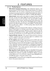
2. FEATURES 2.2.1 Component Locations 1 23 4 28 27 26 25 24 23 56 7 22 21 20 19 18 17 16 15 14 13 12 11 10 9 8 ASUS A7V266-E User's Manual 13 FEATURES Motherboard Parts 2.
2. FEATURES 2.2.1 Component Locations 1 23 4 28 27 26 25 24 23 56 7 22 21 20 19 18 17 16 15 14 13 12 11 10 9 8 ASUS A7V266-E User's Manual 13 FEATURES Motherboard Parts 2.

A7V266-E User Manual
Page 14
H/W SETUP Motherboard Layout 3. HARDWARE SETUP 3.1 Motherboard Layout PS/2 T: Mouse B: Keyboard KBWK USB1 USB2 USB01_PWR COM1 01 01 01 24.5cm (9.64in) DSW CPU_RATIO VID4 VID3 VID2 VID1 PALO_FREQ THEMCPU PR0MISE ...IDE Controller PCI 2 SMARTCARD PCI 3 CD PCI 4 PCI 5 ACR A7V266-E VIA VT8233 Chipset CR2032 3V Lithium Cell CMOS Power ACRUSB SMB_CON JTPWR CLR_RTC ASUS FLOPPY ASIC with Hardware JEN Monitor CHA_FAN CHASSIS CHA IR_CON USB45_PWR IDELED USB23_PWR USB2_3 USB4_5 AFPANEL PANEL 14 ASUS A7V266-E User's Manual ATX Power Connector Primary IDE Secondary IDE 30...
H/W SETUP Motherboard Layout 3. HARDWARE SETUP 3.1 Motherboard Layout PS/2 T: Mouse B: Keyboard KBWK USB1 USB2 USB01_PWR COM1 01 01 01 24.5cm (9.64in) DSW CPU_RATIO VID4 VID3 VID2 VID1 PALO_FREQ THEMCPU PR0MISE ...IDE Controller PCI 2 SMARTCARD PCI 3 CD PCI 4 PCI 5 ACR A7V266-E VIA VT8233 Chipset CR2032 3V Lithium Cell CMOS Power ACRUSB SMB_CON JTPWR CLR_RTC ASUS FLOPPY ASIC with Hardware JEN Monitor CHA_FAN CHASSIS CHA IR_CON USB45_PWR IDELED USB23_PWR USB2_3 USB4_5 AFPANEL PANEL 14 ASUS A7V266-E User's Manual ATX Power Connector Primary IDE Secondary IDE 30...
A7V266-E User Manual
Page 15
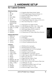
HARDWARE SETUP 3.2 Layout Contents Motherboard Settings 1) JEN p. 18 JumperFree Mode Setting (Disable / Enable) 2) DIP_SW p. 19 CPU External Frequency Selection (Switches 1-4) 3) DSW p. 20 Manual CPU Ratio Settings (Switches 1-5) 4) PALO_FREQ p. 20 FID ... Chassis Fan Connectors (Three 3 pin) 12) USB2_3 / USB4_5 p. 36 USB Headers (10-1 pin) 13) IR_CON p. 37 Standard Infrared Module Connector (10-1 pin) 14) AFPANEL p. 37 ASUS iPanel Connector (12-1 pin) 15) ATXPWR p. 38 ATX Power Supply Connector (20 pin) ASUS A7V266-E User's Manual 15 3. H/W SETUP Layout Contents 3.
HARDWARE SETUP 3.2 Layout Contents Motherboard Settings 1) JEN p. 18 JumperFree Mode Setting (Disable / Enable) 2) DIP_SW p. 19 CPU External Frequency Selection (Switches 1-4) 3) DSW p. 20 Manual CPU Ratio Settings (Switches 1-5) 4) PALO_FREQ p. 20 FID ... Chassis Fan Connectors (Three 3 pin) 12) USB2_3 / USB4_5 p. 36 USB Headers (10-1 pin) 13) IR_CON p. 37 Standard Infrared Module Connector (10-1 pin) 14) AFPANEL p. 37 ASUS iPanel Connector (12-1 pin) 15) ATXPWR p. 38 ATX Power Supply Connector (20 pin) ASUS A7V266-E User's Manual 15 3. H/W SETUP Layout Contents 3.

A7V266-E User Manual
Page 17
... or the power cord is switched off mode, not powered OFF. H/W SETUP Motherboard Settings 01 01 01 A7V266-E A7V266-E Onboard LED LED ON Standby Power OFF Powered Off ASUS A7V266-E User's Manual 17 Failure to do so may cause severe damage to change motherboard function settings through the switches and/or jumpers. Install Expansion Cards 5. Computer...
... or the power cord is switched off mode, not powered OFF. H/W SETUP Motherboard Settings 01 01 01 A7V266-E A7V266-E Onboard LED LED ON Standby Power OFF Powered Off ASUS A7V266-E User's Manual 17 Failure to do so may cause severe damage to change motherboard function settings through the switches and/or jumpers. Install Expansion Cards 5. Computer...

A7V266-E User Manual
Page 18
... below shows all DIP switches (DIP_SW) to OFF. 18 ASUS A7V266-E User's Manual The JumperFree™ mode allows processor settings to enable or disable the JumperFree™ mode. H/W SETUP Motherboard Settings 01 01 01 01 01 01 3. HARDWARE SETUP Motherboard Frequency Settings (DIP Switches) The motherboard frequency is adjusted through the BIOS setup (see 4.4 Advanced...
... below shows all DIP switches (DIP_SW) to OFF. 18 ASUS A7V266-E User's Manual The JumperFree™ mode allows processor settings to enable or disable the JumperFree™ mode. H/W SETUP Motherboard Settings 01 01 01 01 01 01 3. HARDWARE SETUP Motherboard Frequency Settings (DIP Switches) The motherboard frequency is adjusted through the BIOS setup (see 4.4 Advanced...

A7V266-E User Manual
Page 19
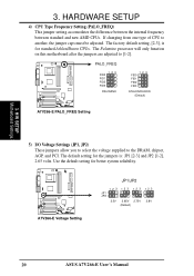
..., [1-2]. (See 1, JumperFree™ Mode (JEN) in 3, HARDWARE SETUP.) 2. IMPORTANT: 1. 3. When JumperFree mode is not recommended. H/W SETUP Motherboard Settings 3. HARDWARE SETUP 2) CPU External Frequency Selection (DIP_SW Switches 1-4) This option tells the clock generator what frequency to send to the recommended settings....12345 8.5X ON 12345 9X ON 12345 9.5X 12345 CPU_RATIO 10X 12345 12345 10.5X (JumperFree Mode) A7V266-E CPU External Clock (BUS) Frequency Selection ASUS A7V266-E User's Manual 19 Set the CPU frequency only to the CPU, DRAM, and the PCI bus. The...
..., [1-2]. (See 1, JumperFree™ Mode (JEN) in 3, HARDWARE SETUP.) 2. IMPORTANT: 1. 3. When JumperFree mode is not recommended. H/W SETUP Motherboard Settings 3. HARDWARE SETUP 2) CPU External Frequency Selection (DIP_SW Switches 1-4) This option tells the clock generator what frequency to send to the recommended settings....12345 8.5X ON 12345 9X ON 12345 9.5X 12345 CPU_RATIO 10X 12345 12345 10.5X (JumperFree Mode) A7V266-E CPU External Clock (BUS) Frequency Selection ASUS A7V266-E User's Manual 19 Set the CPU frequency only to the CPU, DRAM, and the PCI bus. The...
A7V266-E User Manual
Page 20
... 3. The Palomino processor will only function on this motherboard after the jumpers are adjusted to another, the jumper caps must be adjusted. A7V266-E A7V266-E Voltage Setting JP1/JP2 12 3 JP1 JP2 12 3 12 3 2.5V 2.65V 2.75V (Default) 12 3 2.8V 20 ASUS A7V266-E User's Manual 3. The default setting for standard Athlon/Duron CPUs. If changing from...
... 3. The Palomino processor will only function on this motherboard after the jumpers are adjusted to another, the jumper caps must be adjusted. A7V266-E A7V266-E Voltage Setting JP1/JP2 12 3 JP1 JP2 12 3 12 3 2.5V 2.65V 2.75V (Default) 12 3 2.8V 20 ASUS A7V266-E User's Manual 3. The default setting for standard Athlon/Duron CPUs. If changing from...
A7V266-E User Manual
Page 21
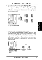
...CD. H/W SETUP Motherboard Settings 01 01 01 01 01 01 7) Bass Center Setting (CENTER/BASS, BASS/CENTER) Use these jumpers in the Line-In, Line-Out, Mic female sockets. A7V266-E A7V266-E Bass Center Setting BCS 12 23 type 1 Bass (CENTER/BASS) (Default) type 2 Bass (BASS/CENTER) ASUS A7V266-E User's Manual... for 4 or 6 speaker audio. Make sure a test is made using the C-Media Audio Driver software setup available on the CPU used. A7V266-E 123 VID4 VID3 VID2 VID1 CPU Default 123 VID4 VID3 VID2 VID1 1.85/1.825Volts 123 1.8/1.775Volts 123 VID4 VID3 VID2 VID1 1.75/1.725Volts 123...
...CD. H/W SETUP Motherboard Settings 01 01 01 01 01 01 7) Bass Center Setting (CENTER/BASS, BASS/CENTER) Use these jumpers in the Line-In, Line-Out, Mic female sockets. A7V266-E A7V266-E Bass Center Setting BCS 12 23 type 1 Bass (CENTER/BASS) (Default) type 2 Bass (BASS/CENTER) ASUS A7V266-E User's Manual... for 4 or 6 speaker audio. Make sure a test is made using the C-Media Audio Driver software setup available on the CPU used. A7V266-E 123 VID4 VID3 VID2 VID1 CPU Default 123 VID4 VID3 VID2 VID1 1.85/1.825Volts 123 1.8/1.775Volts 123 VID4 VID3 VID2 VID1 1.75/1.725Volts 123...

A7V266-E User Manual
Page 22
...default setting for both jumpers accordingly when selecting a device. 3. This feature requires an ATX power supply that can supply at least 300mA on ACR 22 ASUS A7V266-E User's Manual Always set both jumpers is 1-2. (NOTE: The USB port 2 is set to disable or enable the keyboard power up your computer.... jumpers allow you wish to use your keyboard (by pressing ) to Enable but do not have the correct ATX power supply. H/W SETUP Motherboard Settings A7V266-E A7V266-E USB/ACR Selection ACRUSB 12 23 USB to pins 2-3 activates the Advanced Communication Riser (ACR) slot.
...default setting for both jumpers accordingly when selecting a device. 3. This feature requires an ATX power supply that can supply at least 300mA on ACR 22 ASUS A7V266-E User's Manual Always set both jumpers is 1-2. (NOTE: The USB port 2 is set to disable or enable the keyboard power up your computer.... jumpers allow you wish to use your keyboard (by pressing ) to Enable but do not have the correct ATX power supply. H/W SETUP Motherboard Settings A7V266-E A7V266-E USB/ACR Selection ACRUSB 12 23 USB to pins 2-3 activates the Advanced Communication Riser (ACR) slot.
A7V266-E User Manual
Page 23
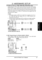
...supply at least 2A on the +5VSB lead when these jumpers to +5V to CPU; H/W SETUP Motherboard Settings 01 01 01 01 01 01 A7V266-E A7V266-E USB Device Wake Up 12 23 USB23_PWR USB45_PWR +5V +5VSB 11) IDE Channel Setting for the ...or in reduced power mode). RAM refreshed; NOTES: 1. 3. Setting JP2601 Enable ATA100 [1-2] (default) Enable RAID 0/1 [2-3] A7V266-E JP2601 2 1 ATA100 (Default) 3 2 RAID0/1 A7V266-E ATA100/RAIDO Selection ASUS A7V266-E User's Manual 23 power supply in sleep mode. 12 23 USB01_PWR +5V +5VSB 3. The default setting enables ATA100....
...supply at least 2A on the +5VSB lead when these jumpers to +5V to CPU; H/W SETUP Motherboard Settings 01 01 01 01 01 01 A7V266-E A7V266-E USB Device Wake Up 12 23 USB23_PWR USB45_PWR +5V +5VSB 11) IDE Channel Setting for the ...or in reduced power mode). RAM refreshed; NOTES: 1. 3. Setting JP2601 Enable ATA100 [1-2] (default) Enable RAID 0/1 [2-3] A7V266-E JP2601 2 1 ATA100 (Default) 3 2 RAID0/1 A7V266-E ATA100/RAIDO Selection ASUS A7V266-E User's Manual 23 power supply in sleep mode. 12 23 USB01_PWR +5V +5VSB 3. The default setting enables ATA100....
A7V266-E User Manual
Page 24
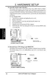
... capability. Short the jumper by the onboard button cell battery. Plug the power cord and turn ON the computer. 6. H/W SETUP Motherboard Settings A7V266-E A7V266-E Clear RTC RAM CR2032 3V Lithium Cell CMOS Power CLRTC Remove and then replace the jumper cap. 13) Thermal Sensor CPU Setting ... selects the type of date, time, and system setup parameters by erasing the CMOS RTC RAM data. A7V266-E THEMCPU 12 23 ATHLON/DURON (Default) RESERVED A7V266-E THEMCPU Setting 24 ASUS A7V266-E User's Manual To erase the RTC RAM: 1. Hold down the key during the boot process and ...
... capability. Short the jumper by the onboard button cell battery. Plug the power cord and turn ON the computer. 6. H/W SETUP Motherboard Settings A7V266-E A7V266-E Clear RTC RAM CR2032 3V Lithium Cell CMOS Power CLRTC Remove and then replace the jumper cap. 13) Thermal Sensor CPU Setting ... selects the type of date, time, and system setup parameters by erasing the CMOS RTC RAM data. A7V266-E THEMCPU 12 23 ATHLON/DURON (Default) RESERVED A7V266-E THEMCPU Setting 24 ASUS A7V266-E User's Manual To erase the RTC RAM: 1. Hold down the key during the boot process and ...

A7V266-E User Manual
Page 25
HARDWARE SETUP 3.5 System Memory This motherboard features three Double Data Rate (DDR) Dual Inline Memory Module sockets. 3.5.1 DDR DIMM Support The three DDR DIMM sockets support 2.5Volt (power level) unbuffered/registered ..., 128MB, 256MB, 512MB, 1GB x1 64MB, 128MB, 256MB, 512MB, 1GB x1 Total System Memory (Max 3GB) = 3. H/W SETUP System Memory ASUS A7V266-E User's Manual 25 DDR DIMMs support non-ECC memory (used on the motherboard. 3. One side (with memory chips) of 64MB, 128MB, 256MB, 512MB, and 1GB to form a memory size between 64MB to...
HARDWARE SETUP 3.5 System Memory This motherboard features three Double Data Rate (DDR) Dual Inline Memory Module sockets. 3.5.1 DDR DIMM Support The three DDR DIMM sockets support 2.5Volt (power level) unbuffered/registered ..., 128MB, 256MB, 512MB, 1GB x1 64MB, 128MB, 256MB, 512MB, 1GB x1 Total System Memory (Max 3GB) = 3. H/W SETUP System Memory ASUS A7V266-E User's Manual 25 DDR DIMMs support non-ECC memory (used on the motherboard. 3. One side (with memory chips) of 64MB, 128MB, 256MB, 512MB, and 1GB to form a memory size between 64MB to...


