
Motherboard DIY Troubleshooting Guide
Page 21
01 01 01 01 01 01 A7V266-E 123 VID4 VID3 VID2 VID1 CPU Default 123 VID4 VID3 VID2 VID1 1.85/1.825Volts 123 1.8/1.775Volts 123 VID4 VID3 VID2 VID1 1.75/1.725Volts 123 1.7/1.675Volts A7V266-E CPU Core Voltage Selection A7V266-E A7V266-E Bass Center Setting BCS 12 23 type 1 Bass (CENTER/BASS) (Default) type 2 Bass (BASS/CENTER) 21
01 01 01 01 01 01 A7V266-E 123 VID4 VID3 VID2 VID1 CPU Default 123 VID4 VID3 VID2 VID1 1.85/1.825Volts 123 1.8/1.775Volts 123 VID4 VID3 VID2 VID1 1.75/1.725Volts 123 1.7/1.675Volts A7V266-E CPU Core Voltage Selection A7V266-E A7V266-E Bass Center Setting BCS 12 23 type 1 Bass (CENTER/BASS) (Default) type 2 Bass (BASS/CENTER) 21

Motherboard DIY Troubleshooting Guide
Page 27
01 01 01 CPU NOTCH TO INNER CORNER A7V266-E A7V266-E Socket A AMD™ CPU LOCK LEVER CPU NOTCH 27
01 01 01 CPU NOTCH TO INNER CORNER A7V266-E A7V266-E Socket A AMD™ CPU LOCK LEVER CPU NOTCH 27
A7V266-E User Manual
Page 4
...Menu Bar 50 4.2.2 Legend Bar 50 4 ASUS A7V266-E User's Manual CONTENTS 1. FEATURES 8 2.1 ASUS A7V266-E Motherboard 8 2.1.1 Specifications 8 2.1.2 Performance... 10 2.1.3 Intelligence 11 2.2 Motherboard Components 12 2.2.1 Component Locations 13 3. HARDWARE SETUP 14 3.1 Motherboard Layout 14 3.2 Layout Contents 15 3.3 Hardware Setup Procedure 17 3.4 Motherboard Settings 17 3.5 System Memory 25 3.5.1 DDR DIMM Support 25 3.5.1 General DIMM Notes 26 3.5.2 Memory Installation 26 3.6 Central Processing Unit (CPU...
...Menu Bar 50 4.2.2 Legend Bar 50 4 ASUS A7V266-E User's Manual CONTENTS 1. FEATURES 8 2.1 ASUS A7V266-E Motherboard 8 2.1.1 Specifications 8 2.1.2 Performance... 10 2.1.3 Intelligence 11 2.2 Motherboard Components 12 2.2.1 Component Locations 13 3. HARDWARE SETUP 14 3.1 Motherboard Layout 14 3.2 Layout Contents 15 3.3 Hardware Setup Procedure 17 3.4 Motherboard Settings 17 3.5 System Memory 25 3.5.1 DDR DIMM Support 25 3.5.1 General DIMM Notes 26 3.5.2 Memory Installation 26 3.6 Central Processing Unit (CPU...

A7V266-E User Manual
Page 9
...cards. • Floppy disk connector: Supports the floppy disk drive. • Wake-On-LAN: Supports Wake-On-LAN activity through an optional ASUS PCI-L101 10 /100 Fast Ethernet PCI card. • Wake-On-Ring: Supports Wake-On-Ring activity through a PCI modem card. &#...connector. The power supply must have at 3D graphical applications using a 4X mode bus. FEATURES Specifications 2. ASUS A7V266-E User's Manual 9 FEATURES • Smart BIOS: 2Mb firmware enables Vcore and CPU/DDR SDRAM frequency adjustments, boot block write protection, and HD/SCSI/MO/ZIP/CD/Floppy boot selection. 2.1.2...
...cards. • Floppy disk connector: Supports the floppy disk drive. • Wake-On-LAN: Supports Wake-On-LAN activity through an optional ASUS PCI-L101 10 /100 Fast Ethernet PCI card. • Wake-On-Ring: Supports Wake-On-Ring activity through a PCI modem card. &#...connector. The power supply must have at 3D graphical applications using a 4X mode bus. FEATURES Specifications 2. ASUS A7V266-E User's Manual 9 FEATURES • Smart BIOS: 2Mb firmware enables Vcore and CPU/DDR SDRAM frequency adjustments, boot block write protection, and HD/SCSI/MO/ZIP/CD/Floppy boot selection. 2.1.2...

A7V266-E User Manual
Page 11
...and Alarm: To prevent system overheat and system damage, the CPU and system fans can access vital information from their computers anywhere. • Temperature Monitoring and Alert: CPU temperature is monitored by the ASUS ASIC through the CPU's internal thermal diode (on battery power for RPM and failure... and management. • Chassis Intrusion Detection: Supports chassis-intrusion monitoring through an internal or external modem. ASUS A7V266-E User's Manual 11 2. FEATURES 2.1.3 Intelligence • Auto Fan Off: The system fans powers off mode, depending on remotely through ...
...and Alarm: To prevent system overheat and system damage, the CPU and system fans can access vital information from their computers anywhere. • Temperature Monitoring and Alert: CPU temperature is monitored by the ASUS ASIC through the CPU's internal thermal diode (on battery power for RPM and failure... and management. • Chassis Intrusion Detection: Supports chassis-intrusion monitoring through an internal or external modem. ASUS A7V266-E User's Manual 11 2. FEATURES 2.1.3 Intelligence • Auto Fan Off: The system fans powers off mode, depending on remotely through ...
A7V266-E User Manual
Page 15
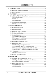
...IDE Channel Setting (ATA100 or RAID 1/0) 12) CLR_RTC p. 24 Clear RTC RAM (2 pin contact) 13) THEMCPU p. 24 Thermal Sensor CPU Setting (Athlon-Duron / Reserved) Expansion Slots/Sockets 1) DIMM 1/2/3 2) Socket 462 3) PCI 1/2/3/4/5 4) AGP Pro 5) ACR Slot p. 25 System Memory Support p. ...CPU/PWR/CHA_FAN p. 36 CPU, Power, and Chassis Fan Connectors (Three 3 pin) 12) USB2_3 / USB4_5 p. 36 USB Headers (10-1 pin) 13) IR_CON p. 37 Standard Infrared Module Connector (10-1 pin) 14) AFPANEL p. 37 ASUS iPanel Connector (12-1 pin) 15) ATXPWR p. 38 ATX Power Supply Connector (20 pin) ASUS A7V266...
...IDE Channel Setting (ATA100 or RAID 1/0) 12) CLR_RTC p. 24 Clear RTC RAM (2 pin contact) 13) THEMCPU p. 24 Thermal Sensor CPU Setting (Athlon-Duron / Reserved) Expansion Slots/Sockets 1) DIMM 1/2/3 2) Socket 462 3) PCI 1/2/3/4/5 4) AGP Pro 5) ACR Slot p. 25 System Memory Support p. ...CPU/PWR/CHA_FAN p. 36 CPU, Power, and Chassis Fan Connectors (Three 3 pin) 12) USB2_3 / USB4_5 p. 36 USB Headers (10-1 pin) 13) IR_CON p. 37 Standard Infrared Module Connector (10-1 pin) 14) AFPANEL p. 37 ASUS iPanel Connector (12-1 pin) 15) ATXPWR p. 38 ATX Power Supply Connector (20 pin) ASUS A7V266...

A7V266-E User Manual
Page 17
... (CPU) 4. WARNING! Computer motherboards and expansion cards contain very delicate Integrated Circuit (IC) chips. Hold components by the edges and try not to a metal object, such as the power supply case, before using your computer. 1. H/W SETUP Motherboard Settings 01 01 01 A7V266-E A7V266-E Onboard LED LED ON Standby Power OFF Powered Off ASUS A7V266-E User...
... (CPU) 4. WARNING! Computer motherboards and expansion cards contain very delicate Integrated Circuit (IC) chips. Hold components by the edges and try not to a metal object, such as the power supply case, before using your computer. 1. H/W SETUP Motherboard Settings 01 01 01 A7V266-E A7V266-E Onboard LED LED ON Standby Power OFF Powered Off ASUS A7V266-E User...

A7V266-E User Manual
Page 19
... 8X ON 12345 8.5X ON 12345 9X ON 12345 9.5X 12345 CPU_RATIO 10X 12345 12345 10.5X (JumperFree Mode) A7V266-E CPU External Clock (BUS) Frequency Selection ASUS A7V266-E User's Manual 19 IMPORTANT: 1. HARDWARE SETUP 2) CPU External Frequency Selection (DIP_SW Switches 1-4) This option tells the clock generator what frequency to send to the internal speed of...
... 8X ON 12345 8.5X ON 12345 9X ON 12345 9.5X 12345 CPU_RATIO 10X 12345 12345 10.5X (JumperFree Mode) A7V266-E CPU External Clock (BUS) Frequency Selection ASUS A7V266-E User's Manual 19 IMPORTANT: 1. HARDWARE SETUP 2) CPU External Frequency Selection (DIP_SW Switches 1-4) This option tells the clock generator what frequency to send to the internal speed of...
A7V266-E User Manual
Page 20
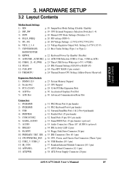
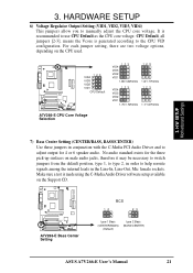
...CPU to [1-2]. The Palomino processor will only function on this motherboard after the jumpers are adjusted to another, the jumper caps must be adjusted. H/W SETUP Motherboard Settings 3. A7V266-E A7V266-E Voltage Setting JP1/JP2 12 3 JP1 JP2 12 3 12 3 2.5V 2.65V 2.75V (Default) 12 3 2.8V 20 ASUS A7V266-E User's Manual A7V266...-E PALO_FREQ FID0 FID1 FID2 FID3 123 PALOMINO FID0 FID1 FID2 FID3 123 ATHLON/DURON (Default) A7V266-E PALO_FREQ Setting 01 01 01 01 01 01 5) I/O Voltage Settings ...
...CPU to [1-2]. The Palomino processor will only function on this motherboard after the jumpers are adjusted to another, the jumper caps must be adjusted. H/W SETUP Motherboard Settings 3. A7V266-E A7V266-E Voltage Setting JP1/JP2 12 3 JP1 JP2 12 3 12 3 2.5V 2.65V 2.75V (Default) 12 3 2.8V 20 ASUS A7V266-E User's Manual A7V266...-E PALO_FREQ FID0 FID1 FID2 FID3 123 PALOMINO FID0 FID1 FID2 FID3 123 ATHLON/DURON (Default) A7V266-E PALO_FREQ Setting 01 01 01 01 01 01 5) I/O Voltage Settings ...
A7V266-E User Manual
Page 21
...or 6 speaker audio. Make sure a test is recommended to manually adjust the CPU core voltage. 3. A7V266-E A7V266-E Bass Center Setting BCS 12 23 type 1 Bass (CENTER/BASS) (Default) type 2 Bass (BASS/CENTER) ASUS A7V266-E User's Manual 21 It is made using the C-Media Audio Driver software setup... available on the Support CD. CPU Default, all jumpers [2-3], means the Vcore is generated according to adjust output for...
...or 6 speaker audio. Make sure a test is recommended to manually adjust the CPU core voltage. 3. A7V266-E A7V266-E Bass Center Setting BCS 12 23 type 1 Bass (CENTER/BASS) (Default) type 2 Bass (BASS/CENTER) ASUS A7V266-E User's Manual 21 It is made using the C-Media Audio Driver software setup... available on the Support CD. CPU Default, all jumpers [2-3], means the Vcore is generated according to adjust output for...
A7V266-E User Manual
Page 23
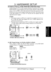
... SETUP Motherboard Settings 01 01 01 01 01 01 A7V266-E A7V266-E USB Device Wake Up 12 23 USB23_PWR USB45_PWR +5V +5VSB 11) IDE Channel Setting for the three jumpers is 1-2 to CPU; The default setting enables ATA100. The total current consumed...CPU stopped; Otherwise, the system does not power up from S3 sleep state (no power to select +5V (because not all computers have the appropriate power supply). Setting JP2601 Enable ATA100 [1-2] (default) Enable RAID 0/1 [2-3] A7V266-E JP2601 2 1 ATA100 (Default) 3 2 RAID0/1 A7V266-E ATA100/RAIDO Selection ASUS A7V266...
... SETUP Motherboard Settings 01 01 01 01 01 01 A7V266-E A7V266-E USB Device Wake Up 12 23 USB23_PWR USB45_PWR +5V +5VSB 11) IDE Channel Setting for the three jumpers is 1-2 to CPU; The default setting enables ATA100. The total current consumed...CPU stopped; Otherwise, the system does not power up from S3 sleep state (no power to select +5V (because not all computers have the appropriate power supply). Setting JP2601 Enable ATA100 [1-2] (default) Enable RAID 0/1 [2-3] A7V266-E JP2601 2 1 ATA100 (Default) 3 2 RAID0/1 A7V266-E ATA100/RAIDO Selection ASUS A7V266...
A7V266-E User Manual
Page 24
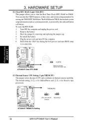
...OFF the computer and unplug the power cord. 2. H/W SETUP Motherboard Settings A7V266-E A7V266-E Clear RTC RAM CR2032 3V Lithium Cell CMOS Power CLRTC Remove and then replace the jumper cap. 13) Thermal Sensor CPU Setting (2-pin THEMCPU) This jumper selects the type of date, time, ... is powered by the onboard button cell battery. Plug the power cord and turn ON the computer. 6. A7V266-E THEMCPU 12 23 ATHLON/DURON (Default) RESERVED A7V266-E THEMCPU Setting 24 ASUS A7V266-E User's Manual HARDWARE SETUP 12) Clear RTC RAM (2-pin CLR_RTC) This jumper allows you to re-enter...
...OFF the computer and unplug the power cord. 2. H/W SETUP Motherboard Settings A7V266-E A7V266-E Clear RTC RAM CR2032 3V Lithium Cell CMOS Power CLRTC Remove and then replace the jumper cap. 13) Thermal Sensor CPU Setting (2-pin THEMCPU) This jumper selects the type of date, time, ... is powered by the onboard button cell battery. Plug the power cord and turn ON the computer. 6. A7V266-E THEMCPU 12 23 ATHLON/DURON (Default) RESERVED A7V266-E THEMCPU Setting 24 ASUS A7V266-E User's Manual HARDWARE SETUP 12) Clear RTC RAM (2-pin CLR_RTC) This jumper allows you to re-enter...

A7V266-E User Manual
Page 27
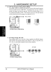
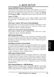
... With the added weight of the CPU must be attached to the CPU to keep the CPU in one orientation and should drop easily into its alignment and look for CPU installation. Refer to avoid start-up problems. ASUS A7V266-E User's Manual 27 If the CPU does not fit, check its locked... position. 4. When mounting a heatsink onto your CPU, make sure that exposed CPU capacitors do not touch the heatsink, or ...
... With the added weight of the CPU must be attached to the CPU to keep the CPU in one orientation and should drop easily into its alignment and look for CPU installation. Refer to avoid start-up problems. ASUS A7V266-E User's Manual 27 If the CPU does not fit, check its locked... position. 4. When mounting a heatsink onto your CPU, make sure that exposed CPU capacitors do not touch the heatsink, or ...

A7V266-E User Manual
Page 28
... on the slot you intend to change the settings.) 7. Change the necessary BIOS settings, if any necessary hardware settings for the expansion card. 3. H/W SETUP CPU Installation 28 ASUS A7V266-E User's Manual 3. The motherboard has five PCI expansion slots to the slot with the screw you may cause severe damage to install expansion cards...
... on the slot you intend to change the settings.) 7. Change the necessary BIOS settings, if any necessary hardware settings for the expansion card. 3. H/W SETUP CPU Installation 28 ASUS A7V266-E User's Manual 3. The motherboard has five PCI expansion slots to the slot with the screw you may cause severe damage to install expansion cards...

A7V266-E User Manual
Page 36
HARDWARE SETUP 11) CPU Fan, Power Fan, and Chassis Fan Connectors (CPU_FAN, PWR_FAN, CHA_FAN) The three fan connectors support cooling fans of the expansion slots. You can monitor the Rotations Per Minute (RPM) using ASUS PC Probe (see 6. Connect a 2-port USB connector set to a USB header and mount... headers are not jumpers, do not place jumper caps over these connectors! 01 01 01 01 01 01 3. USBP2+ GND NC A7V266-E Front Panel USB Headers 36 ASUS A7V266-E User's Manual SOFTWARE REFERENCE). Orient the fans so that the black wire matches the ground pin. (NOTE: Use the "Rotation...
HARDWARE SETUP 11) CPU Fan, Power Fan, and Chassis Fan Connectors (CPU_FAN, PWR_FAN, CHA_FAN) The three fan connectors support cooling fans of the expansion slots. You can monitor the Rotations Per Minute (RPM) using ASUS PC Probe (see 6. Connect a 2-port USB connector set to a USB header and mount... headers are not jumpers, do not place jumper caps over these connectors! 01 01 01 01 01 01 3. USBP2+ GND NC A7V266-E Front Panel USB Headers 36 ASUS A7V266-E User's Manual SOFTWARE REFERENCE). Orient the fans so that the black wire matches the ground pin. (NOTE: Use the "Rotation...

A7V266-E User Manual
Page 44
... frequency beeps when system is working Meaning No error during POST No DRAM installed or detected Video card not found or video card memory bad CPU overheated System running , the BIOS beeps or additional messages appear on the chain) c. If you need to enter BIOS Setup. Monitor b. While...on , hold down the operating system. The system then runs the power-on the devices in some systems, marked with ATX power supplies. 44 ASUS A7V266-E User's Manual The power supply should turn off (in the following order: a. Connect the AC cord to an outlet equipped with the last ...
... frequency beeps when system is working Meaning No error during POST No DRAM installed or detected Video card not found or video card memory bad CPU overheated System running , the BIOS beeps or additional messages appear on the chain) c. If you need to enter BIOS Setup. Monitor b. While...on , hold down the operating system. The system then runs the power-on the devices in some systems, marked with ATX power supplies. 44 ASUS A7V266-E User's Manual The power supply should turn off (in the following order: a. Connect the AC cord to an outlet equipped with the last ...

A7V266-E User Manual
Page 58
... this field sets the frequency multiple between the CPU's internal frequency (CPU speed) and the external frequency. Note that selecting a frequency higher than the CPU manufacturer recommends may cause the system to 227/57. 58 ASUS A7V266-E User's Manual Configuration options: [Manual] [750MHz] [1000MHz] CPU : System Frequency Multiple, (if CPU Speed set to [Manual]) This field is...
... this field sets the frequency multiple between the CPU's internal frequency (CPU speed) and the external frequency. Note that selecting a frequency higher than the CPU manufacturer recommends may cause the system to 227/57. 58 ASUS A7V266-E User's Manual Configuration options: [Manual] [750MHz] [1000MHz] CPU : System Frequency Multiple, (if CPU Speed set to [Manual]) This field is...
A7V266-E User Manual
Page 59
...BIOS always reserves IRQ12, whether or not a PS/2 mouse is set this option to [Enabled], the BIOS loads the update on or off the CPU Level 1 and Level 2 built-in the popup menu vary according to the default setting [Disabled]. Configuration options: [Disabled] [Enabled] [Auto]... [Enabled] This field functions as an update loader integrated into the BIOS to [Disabled], the USB controller is disabled. BIOS SETUP Advanced Menu ASUS A7V266-E User's Manual 59 4. Configuration options: [Disabled] [Enabled] PS/2 Mouse Function Control [Auto] The default setting [Auto] allows the system...
...BIOS always reserves IRQ12, whether or not a PS/2 mouse is set this option to [Enabled], the BIOS loads the update on or off the CPU Level 1 and Level 2 built-in the popup menu vary according to the default setting [Disabled]. Configuration options: [Disabled] [Enabled] [Auto]... [Enabled] This field functions as an update loader integrated into the BIOS to [Disabled], the USB controller is disabled. BIOS SETUP Advanced Menu ASUS A7V266-E User's Manual 59 4. Configuration options: [Disabled] [Enabled] PS/2 Mouse Function Control [Auto] The default setting [Auto] allows the system...

A7V266-E User Manual
Page 60
For processors with a popup display of 100MHz and a fail-safe CPU internal frequency. BIOS SETUP Notes for JumperFree Mode CPU Upgrade/Reinstallation To ensure that the system can enter BIOS Setup after changing the processor, the system starts up running at a bus speed of all the possible CPU internal frequencies. BIOS SETUP JumperFree Mode 60 ASUS A7V266-E User's Manual Then it automatically enters the Advanced menu with locked frequency multiplier 4. 4.
For processors with a popup display of 100MHz and a fail-safe CPU internal frequency. BIOS SETUP Notes for JumperFree Mode CPU Upgrade/Reinstallation To ensure that the system can enter BIOS Setup after changing the processor, the system starts up running at a bus speed of all the possible CPU internal frequencies. BIOS SETUP JumperFree Mode 60 ASUS A7V266-E User's Manual Then it automatically enters the Advanced menu with locked frequency multiplier 4. 4.

A7V266-E User Manual
Page 61
The system starts up in safe mode running at a bus speed of 100MHz and enters the BIOS Setup. 4. BIOS SETUP System Hangup If the system crashes or hangs due to improper frequency settings, power OFF the system and restart. Cause for Hangup: Improper CPU Speed Cause for Hangup: Improper CPU: System Frequency Multiple (For processors with unlocked frequency multiplier only) Cause for Hangup: Improper System/SDRAM Frequency 4. BIOS SETUP JumperFree Mode ASUS A7V266-E User's Manual 61
The system starts up in safe mode running at a bus speed of 100MHz and enters the BIOS Setup. 4. BIOS SETUP System Hangup If the system crashes or hangs due to improper frequency settings, power OFF the system and restart. Cause for Hangup: Improper CPU Speed Cause for Hangup: Improper CPU: System Frequency Multiple (For processors with unlocked frequency multiplier only) Cause for Hangup: Improper System/SDRAM Frequency 4. BIOS SETUP JumperFree Mode ASUS A7V266-E User's Manual 61


