Motherboard DIY Troubleshooting Guide
Page 4
... 3.2 Layout Contents 15 3.3 Hardware Setup Procedure 16 3.4 Motherboard Settings 16 3.5 System Memory (DIMM 20 3.5.1 General DIMM Notes 20 3.5.2 Memory Installation 21 3.6 Central Processing Unit (CPU 23 3.7 Expansion Cards 24 3.7.1 Expansion Card... 44 4.2.1 BIOS Menu Bar 45 4.2.2 Legend Bar 45 4.3 Main Menu 47 4.3.1 Primary & Secondary Master/Slave 48 4 ASUS A7V-E User's Manual FEATURES 8 2.1 The ASUS A7V-E 8 2.1.1 Specifications 8 2.1.2 Special Features 10 2.1.3 Optional Components 10 2.1.4 Performance Features 10 2.1.5 Intelligence 11 2.2 Motherboard Components...
... 3.2 Layout Contents 15 3.3 Hardware Setup Procedure 16 3.4 Motherboard Settings 16 3.5 System Memory (DIMM 20 3.5.1 General DIMM Notes 20 3.5.2 Memory Installation 21 3.6 Central Processing Unit (CPU 23 3.7 Expansion Cards 24 3.7.1 Expansion Card... 44 4.2.1 BIOS Menu Bar 45 4.2.2 Legend Bar 45 4.3 Main Menu 47 4.3.1 Primary & Secondary Master/Slave 48 4 ASUS A7V-E User's Manual FEATURES 8 2.1 The ASUS A7V-E 8 2.1.1 Specifications 8 2.1.2 Special Features 10 2.1.3 Optional Components 10 2.1.4 Performance Features 10 2.1.5 Intelligence 11 2.2 Motherboard Components...
Motherboard DIY Troubleshooting Guide
Page 8
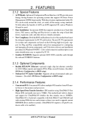
... 2.1 The ASUS A7V-E The ASUS A7V-E motherboard is optimized to deliver enhanced AMD Athlon™/Duron™ processor system performance. • "Super South" South Bridge System PCIset: VIA VT82C686B PCIset with PCI Super-I/O Integrated Peripheral Controller (PSIPC) with two connectors that dramatically improves the memory system's ability...100 Fast Ethernet PCI card (see 7. Easy-to-use DIP switches instead of jumpers are included to 100MB/sec; Appendix). 8 ASUS A7V-E User's Manual Supports UltraDMA/100, UltraDMA/66, UltraDMA/33, PIO Modes 3 & 4 and Bus Master IDE DMA Mode 2, ...
... 2.1 The ASUS A7V-E The ASUS A7V-E motherboard is optimized to deliver enhanced AMD Athlon™/Duron™ processor system performance. • "Super South" South Bridge System PCIset: VIA VT82C686B PCIset with PCI Super-I/O Integrated Peripheral Controller (PSIPC) with two connectors that dramatically improves the memory system's ability...100 Fast Ethernet PCI card (see 7. Easy-to-use DIP switches instead of jumpers are included to 100MB/sec; Appendix). 8 ASUS A7V-E User's Manual Supports UltraDMA/100, UltraDMA/66, UltraDMA/33, PIO Modes 3 & 4 and Bus Master IDE DMA Mode 2, ...
Motherboard DIY Troubleshooting Guide
Page 9
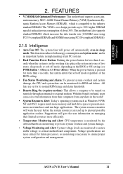
..., such as CPU and systerm voltages, temperatures, and fan status through the onboard hardware monitoring and the bundled ASUS PC Probe. • SMBus: Features the System Management Bus interface, which is used to physically transport commands ...virtually automatic setup. • Concurrent PCI: Concurrent PCI allows multiple PCI transfers from PCI master busses to the memory and processor. • Smart BIOS: 2Mb firmware provides Vcore and CPU/SDRAM frequency adjustments, boot block write ... PC 99 compliancy, major connectors in this motherboard are color-coded. ASUS A7V-E User's Manual 9
..., such as CPU and systerm voltages, temperatures, and fan status through the onboard hardware monitoring and the bundled ASUS PC Probe. • SMBus: Features the System Management Bus interface, which is used to physically transport commands ...virtually automatic setup. • Concurrent PCI: Concurrent PCI allows multiple PCI transfers from PCI master busses to the memory and processor. • Smart BIOS: 2Mb firmware provides Vcore and CPU/SDRAM frequency adjustments, boot block write ... PC 99 compliancy, major connectors in this motherboard are color-coded. ASUS A7V-E User's Manual 9
Motherboard DIY Troubleshooting Guide
Page 10
...2.1.4 Performance Features • Concurrent PCI: Concurrent PCI allows multiple PCI transfers from PCI master busses to the memory and processor. • High-Speed Data Transfer Interface: IDE transfers using UltraDMA/33 Bus Master IDE can... ACPI, an ACPI-supported OS, such as required by PC 99. • Symbios SCSI BIOS: Supports optional ASUS SCSI controller cards through the onboard SYMBIOS firmware. 2.1.3 Optional Components • Realtek RTL8139C Ethernet: (optional) single... identification easy as Windows 98 must be enabled.) 10 ASUS A7V-E User's Manual FEA TURES Performance 2.
...2.1.4 Performance Features • Concurrent PCI: Concurrent PCI allows multiple PCI transfers from PCI master busses to the memory and processor. • High-Speed Data Transfer Interface: IDE transfers using UltraDMA/33 Bus Master IDE can... ACPI, an ACPI-supported OS, such as required by PC 99. • Symbios SCSI BIOS: Supports optional ASUS SCSI controller cards through the onboard SYMBIOS firmware. 2.1.3 Optional Components • Realtek RTL8139C Ethernet: (optional) single... identification easy as Windows 98 must be enabled.) 10 ASUS A7V-E User's Manual FEA TURES Performance 2.
Motherboard DIY Troubleshooting Guide
Page 11
... in the world! • System Resources Alert: Today's operating systems such as Windows 95/98/ NT and OS/2, require much more memory and hard drive space to ensure proper system configuration and management. Voltage specifications are monitored to ensure stable voltage to be monitored for its normal... are set for RPM and failure. The system resource monitor will power off mode, depending on remotely through an internal or external modem. ASUS A7V-E User's Manual 11 The VCM's core design provides up to 50% higher SDRAM speed at reduced power consumption of two states: sleep ...
... in the world! • System Resources Alert: Today's operating systems such as Windows 95/98/ NT and OS/2, require much more memory and hard drive space to ensure proper system configuration and management. Voltage specifications are monitored to ensure stable voltage to be monitored for its normal... are set for RPM and failure. The system resource monitor will power off mode, depending on remotely through an internal or external modem. ASUS A7V-E User's Manual 11 The VCM's core design provides up to 50% higher SDRAM speed at reduced power consumption of two states: sleep ...
Motherboard DIY Troubleshooting Guide
Page 12
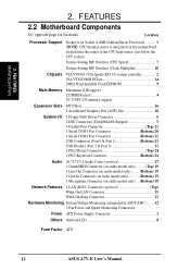
...Multiplier 10 Chipsets VIA VT8363 (VIA Apollo KT133) system controller 2 VIA VT82C686B PCIset 14 2Mbit Programmable Flash EEPROM 9 Main Memory Maximum 1GB support 2 DIMM Sockets 4 VC133/PC133 memory support Expansion Slots 6PCI Slots 16 1 Accelerated Graphics Port (AGP) Slot 18 System I/O 1 Floppy Disk Driver Connector ...Top) Wake-On-LAN Connector 15 Wake-On-Ring Connector 13 Hardware Monitoring System Voltage Monitoring (integrated in ASUS ASIC) ....... 12 3 Fan Power and Speed Monitoring Connectors Power ATX Power Supply Connector 1 Others Onboard LED 8 Form Factor ATX 12...
...Multiplier 10 Chipsets VIA VT8363 (VIA Apollo KT133) system controller 2 VIA VT82C686B PCIset 14 2Mbit Programmable Flash EEPROM 9 Main Memory Maximum 1GB support 2 DIMM Sockets 4 VC133/PC133 memory support Expansion Slots 6PCI Slots 16 1 Accelerated Graphics Port (AGP) Slot 18 System I/O 1 Floppy Disk Driver Connector ...Top) Wake-On-LAN Connector 15 Wake-On-Ring Connector 13 Hardware Monitoring System Voltage Monitoring (integrated in ASUS ASIC) ....... 12 3 Fan Power and Speed Monitoring Connectors Power ATX Power Supply Connector 1 Others Onboard LED 8 Form Factor ATX 12...
Motherboard DIY Troubleshooting Guide
Page 14
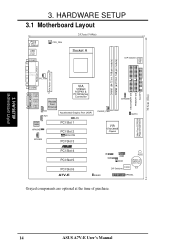
... 168-pin module) ATX Power Connector PARALLEL PORT PS_FAN GAME_AUDIO COM2 Line Out Line In Mic In Audio Codec VIA VT8363 AGP4X & PC133 Memory Controller Realtek Fast Enternet CD AUX Accelerated Graphic Port (AGP) JEN PCI Slot 1 HPHONE MODEM PCI Slot 2 WOLCON PCI Slot 3 CHASSIS...; PCI Slot 4 PCI Slot 5 PCI Slot 6 IR SMB USB2 WOR PLED CR2032 3V Lithium Cell CMOS Power DSFID DIP Switches A7V-E IDELED HPANEL Grayed components are optional at the time of purchase. 14 ASUS A7V-E User's Manual SECONDARY IDE PRIMARY IDE FLOPPY 30.6cm (12in) 3. H/W SETUP Motherboard Layout 3.
... 168-pin module) ATX Power Connector PARALLEL PORT PS_FAN GAME_AUDIO COM2 Line Out Line In Mic In Audio Codec VIA VT8363 AGP4X & PC133 Memory Controller Realtek Fast Enternet CD AUX Accelerated Graphic Port (AGP) JEN PCI Slot 1 HPHONE MODEM PCI Slot 2 WOLCON PCI Slot 3 CHASSIS...; PCI Slot 4 PCI Slot 5 PCI Slot 6 IR SMB USB2 WOR PLED CR2032 3V Lithium Cell CMOS Power DSFID DIP Switches A7V-E IDELED HPANEL Grayed components are optional at the time of purchase. 14 ASUS A7V-E User's Manual SECONDARY IDE PRIMARY IDE FLOPPY 30.6cm (12in) 3. H/W SETUP Motherboard Layout 3.
Motherboard DIY Troubleshooting Guide
Page 15
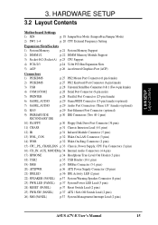
... Layout Contents Motherboard Settings 1) JEN p. 18 JumperFree Mode (JumperFree/Jumper Mode) 2) SW1 1-4 p. 20 CPU External Frequency Setting Expansion Slots/Sockets 1) System Memory p.21 System Memory Support 2) DIMM1/2 p.22 DIMM Memory Module Support 3) Socket 462 (Socket A) p.23 CPU Support 4) PCI1/2/3 p.24 32-bit PCI Bus Expansion Slots 5) AGP p.26 Accelerated Graphics Port (... Lead (2 pins) 25) PWR.SW (PANEL) p.37 ATX / Soft-Off Switch Lead (2 pins) 26) SMI (PANEL) p.37 System Management Interrupt Lead (2 pins) ASUS A7V-E User's Manual 15 H/W SETUP Layout Contents 3.
... Layout Contents Motherboard Settings 1) JEN p. 18 JumperFree Mode (JumperFree/Jumper Mode) 2) SW1 1-4 p. 20 CPU External Frequency Setting Expansion Slots/Sockets 1) System Memory p.21 System Memory Support 2) DIMM1/2 p.22 DIMM Memory Module Support 3) Socket 462 (Socket A) p.23 CPU Support 4) PCI1/2/3 p.24 32-bit PCI Bus Expansion Slots 5) AGP p.26 Accelerated Graphics Port (... Lead (2 pins) 25) PWR.SW (PANEL) p.37 ATX / Soft-Off Switch Lead (2 pins) 26) SMI (PANEL) p.37 System Management Interrupt Lead (2 pins) ASUS A7V-E User's Manual 15 H/W SETUP Layout Contents 3.
Motherboard DIY Troubleshooting Guide
Page 16
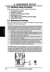
... how to touch the IC chips, leads or connectors, or other components. 4. H/W SETUP 01 01 ® A7V-E A7V-E Onboard LED ON Standby Power OFF Powered Off 16 ASUS A7V-E User's Manual 3. Computer motherboards and expansion cards contain very delicate Integrated Circuit (IC) chips. Hold components by ...the system is switched off mode and not powered OFF. 3. The onboard LED when lit acts as the power supply case. 3. Install Memory Modules 3. To protect them against damage from the system. 5. Unplug your power supply when adding or removing system components. WARNING! Place ...
... how to touch the IC chips, leads or connectors, or other components. 4. H/W SETUP 01 01 ® A7V-E A7V-E Onboard LED ON Standby Power OFF Powered Off 16 ASUS A7V-E User's Manual 3. Computer motherboards and expansion cards contain very delicate Integrated Circuit (IC) chips. Hold components by ...the system is switched off mode and not powered OFF. 3. The onboard LED when lit acts as the power supply case. 3. Install Memory Modules 3. To protect them against damage from the system. 5. Unplug your power supply when adding or removing system components. WARNING! Place ...
Motherboard DIY Troubleshooting Guide
Page 20
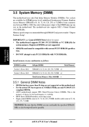
...be compatible with current PC133 SDRAM specification. • DO NOT attempt to mix PC133 SDRAMs with memory chips) of choice for system memory. WARNING! compliant DIMMs. • ASUS motherboards support SPD (Serial Presence Detect) DIMMs. This is recommended through SDRAM Configuration under "Chipset ... 16, 32, 64, 128, 256, 512MB x1 Total System Memory (Max 1024MB) = 3.5.1 General DIMM Notes • DIMMs that the DIMM you use only PC100-/PC133- Two sockets are not supported. • SDRAMs used must be possible. 20 ASUS A7V-E User's Manual stability. • BIOS shows SDRAM...
...be compatible with current PC133 SDRAM specification. • DO NOT attempt to mix PC133 SDRAMs with memory chips) of choice for system memory. WARNING! compliant DIMMs. • ASUS motherboards support SPD (Serial Presence Detect) DIMMs. This is recommended through SDRAM Configuration under "Chipset ... 16, 32, 64, 128, 256, 512MB x1 Total System Memory (Max 1024MB) = 3.5.1 General DIMM Notes • DIMMs that the DIMM you use only PC100-/PC133- Two sockets are not supported. • SDRAMs used must be possible. 20 ASUS A7V-E User's Manual stability. • BIOS shows SDRAM...
Motherboard DIY Troubleshooting Guide
Page 21
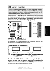
... wrong type from being inserted into the DIMM slot on both your retailer the correct DIMM type before purchasing. H/W SETUP System Memory DRAM Key Position Voltage Key Position RFU Unbuffered Buffered 5.0V Reserved 3.3V The notches on the DIMM will only fit in the... information). Make sure that you unplug your power supply when adding or removing memory modules or other system components. 01 01 3.5.2 Memory Installation WARNING! SDRAM DIMMs have different pin contacts on each side and therefore have the same pin contacts on the motherboard. ASUS A7V-E User's Manual 21
... wrong type from being inserted into the DIMM slot on both your retailer the correct DIMM type before purchasing. H/W SETUP System Memory DRAM Key Position Voltage Key Position RFU Unbuffered Buffered 5.0V Reserved 3.3V The notches on the DIMM will only fit in the... information). Make sure that you unplug your power supply when adding or removing memory modules or other system components. 01 01 3.5.2 Memory Installation WARNING! SDRAM DIMMs have different pin contacts on each side and therefore have the same pin contacts on the motherboard. ASUS A7V-E User's Manual 21

Motherboard DIY Troubleshooting Guide
Page 22
H/W SETUP System Memory 22 ASUS A7V-E User's Manual 3. HARDWARE SETUP (This page intentionally left blank.) 3.
H/W SETUP System Memory 22 ASUS A7V-E User's Manual 3. HARDWARE SETUP (This page intentionally left blank.) 3.
Motherboard DIY Troubleshooting Guide
Page 39
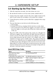
... beeps High frequency beeps when system is working Meaning No error during POST No DRAM installed or detected Video card not found or video card memory bad CPU overheated System running , the BIOS will alarm beeps or additional messages will then run power-on the front of the system case will... the monitor may have failed a power-on the chain) c. Connect the power supply cord into a power outlet that all connections are running at a lower frequency ASUS A7V-E User's Manual 39 HARDWARE SETUP 3.9 Starting Up the First Time 1.
... beeps High frequency beeps when system is working Meaning No error during POST No DRAM installed or detected Video card not found or video card memory bad CPU overheated System running , the BIOS will alarm beeps or additional messages will then run power-on the front of the system case will... the monitor may have failed a power-on the chain) c. Connect the power supply cord into a power outlet that all connections are running at a lower frequency ASUS A7V-E User's Manual 39 HARDWARE SETUP 3.9 Starting Up the First Time 1.
Motherboard DIY Troubleshooting Guide
Page 41
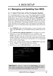
... Type FORMAT A:/S at the DOS prompt to the disk. 2. DO NOT copy AUTOEXEC.BAT & CONFIG.SYS to create a bootable system floppy disk. ASUS A7V-E User's Manual 41 Type COPY D:\AFLASH\AFLASH.EXE A:\ (assuming D is not supported by the ACPI BIOS and therefore, cannot be loaded when you... reboot using a floppy. 3. It will not work with DOS prompt in Windows and will not work with a Flash Memory Writer utility (AFLASH.EXE) to a bootable floppy disk in DOS mode. BIOS SETUP Updating BIOS IMPORTANT! Larger numbers represent a newer BIOS file. 1. ...
... Type FORMAT A:/S at the DOS prompt to the disk. 2. DO NOT copy AUTOEXEC.BAT & CONFIG.SYS to create a bootable system floppy disk. ASUS A7V-E User's Manual 41 Type COPY D:\AFLASH\AFLASH.EXE A:\ (assuming D is not supported by the ACPI BIOS and therefore, cannot be loaded when you... reboot using a floppy. 3. It will not work with DOS prompt in Windows and will not work with a Flash Memory Writer utility (AFLASH.EXE) to a bootable floppy disk in DOS mode. BIOS SETUP Updating BIOS IMPORTANT! Larger numbers represent a newer BIOS file. 1. ...
Motherboard DIY Troubleshooting Guide
Page 43
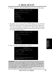
... only when necessary. WARNING! This will minimize the chance that a failed update will need servicing. ASUS A7V-E User's Manual 43 If you saved to boot up . Follow the onscreen instructions to start the update. 7. If the Flash Memory Writer utility was not able to program the new BIOS information into the flash ROM...
... only when necessary. WARNING! This will minimize the chance that a failed update will need servicing. ASUS A7V-E User's Manual 43 If you saved to boot up . Follow the onscreen instructions to start the update. 7. If the Flash Memory Writer utility was not able to program the new BIOS information into the flash ROM...

Motherboard DIY Troubleshooting Guide
Page 52
... and press . You can clear the password by the system during system startup. To clear the password, highlight this field. 52 ASUS A7V-E User's Manual In other keys are not case sensitive. When enabled, the Supervisor password is available. BIOS SETUP 01 01 CLRTC Short... solder points ® to eight alphanumeric characters. BIOS SETUP Language [English] This allows selection of conventional memory detected by erasing the CMOS Real Time Clock (RTC) RAM. Supervisor Password [Disabled] / User Password [Disabled] These fields allow you can...
... and press . You can clear the password by the system during system startup. To clear the password, highlight this field. 52 ASUS A7V-E User's Manual In other keys are not case sensitive. When enabled, the Supervisor password is available. BIOS SETUP 01 01 CLRTC Short... solder points ® to eight alphanumeric characters. BIOS SETUP Language [English] This allows selection of conventional memory detected by erasing the CMOS Real Time Clock (RTC) RAM. Supervisor Password [Disabled] / User Password [Disabled] These fields allow you can...

Motherboard DIY Troubleshooting Guide
Page 53
...frequency of your CPU. The bus frequency (external frequency) multiplied by 4/3. This must be set to JumperFree™ mode, this section. ASUS A7V-E User's Manual 53 BIOS SETUP Advanced Menu Operating Frequency Setting [User Define] When the motherboard is set to be fixed at 100MHz. ...is set in synchronous or asynchronous mode with CPU (external) Frequency to the CPU Frequency. DRAM Frequency This field determines whether the memory clock frequency is the CPU Frequency multiplied by the bus multiple equals the CPU speed (the CPU's internal frequency). Note that ...
...frequency of your CPU. The bus frequency (external frequency) multiplied by 4/3. This must be set to JumperFree™ mode, this section. ASUS A7V-E User's Manual 53 BIOS SETUP Advanced Menu Operating Frequency Setting [User Define] When the motherboard is set to be fixed at 100MHz. ...is set in synchronous or asynchronous mode with CPU (external) Frequency to the CPU Frequency. DRAM Frequency This field determines whether the memory clock frequency is the CPU Frequency multiplied by the bus multiple equals the CPU speed (the CPU's internal frequency). Note that ...
Motherboard DIY Troubleshooting Guide
Page 54
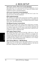
...This motherboard supports Universal Serial Bus (USB) devices. When this field is set this on startup. Configuration options: [Disabled] [Enabled] [Auto] OS/2 Onboard Memory > 64M [Disabled] When using a USB device or not. 4. Configuration options: [Disabled] [Enabled] BIOS Update [Enabled] This functions as an update ... is detected or not. If detected, IRQ12 will be disabled. The default of [Enabled], the BIOS will be enabled. BIOS SETUP 54 ASUS A7V-E User's Manual If not detected, the USB controller will be used for expansion cards only if a PS/2 mouse is not detected. ...
...This motherboard supports Universal Serial Bus (USB) devices. When this field is set this on startup. Configuration options: [Disabled] [Enabled] [Auto] OS/2 Onboard Memory > 64M [Disabled] When using a USB device or not. 4. Configuration options: [Disabled] [Enabled] BIOS Update [Enabled] This functions as an update ... is detected or not. If detected, IRQ12 will be disabled. The default of [Enabled], the BIOS will be enabled. BIOS SETUP 54 ASUS A7V-E User's Manual If not detected, the USB controller will be used for expansion cards only if a PS/2 mouse is not detected. ...

Motherboard DIY Troubleshooting Guide
Page 57
... Read Caching Default: [Enabled] for Athlon Processors / [Disabled] for SDRAM related fields, depending on default setting. BIOS SETUP Chip Configuration ASUS A7V-E User's Manual 57 Select [Disabled] for Duron Processors Leave on the memory modules that are not PCI 2.1 compliant. Configuration options: [Disabled] [Enabled] PCI to [User Define]. 4. NOTE: This field will only...
... Read Caching Default: [Enabled] for Athlon Processors / [Disabled] for SDRAM related fields, depending on default setting. BIOS SETUP Chip Configuration ASUS A7V-E User's Manual 57 Select [Disabled] for Duron Processors Leave on the memory modules that are not PCI 2.1 compliant. Configuration options: [Disabled] [Enabled] PCI to [User Define]. 4. NOTE: This field will only...

Motherboard DIY Troubleshooting Guide
Page 58
...; otherwise your display card cannot support this to select the size of mapped memory for the video memory of the processor. Configuration options: [UC] [USWC] 4. BIOS SETUP 58 ASUS A7V-E User's Manual Configuration options: [4MB] [8MB] [16MB] [32MB] [64MB] [128MB] [256MB] Video Memory Cache Mode [UC] USWC (uncacheable, speculative write combining) is a new cache technology...
...; otherwise your display card cannot support this to select the size of mapped memory for the video memory of the processor. Configuration options: [UC] [USWC] 4. BIOS SETUP 58 ASUS A7V-E User's Manual Configuration options: [4MB] [8MB] [16MB] [32MB] [64MB] [128MB] [256MB] Video Memory Cache Mode [UC] USWC (uncacheable, speculative write combining) is a new cache technology...


