Motherboard DIY Troubleshooting Guide
Page 2
... AND SOFTWARE DESCRIBED IN IT. Copyright © 2001 ASUSTeK COMPUTER INC. Product Name: ASUS A7V-E Manual Revision: 1.01 E746 Release Date: March 2001 2 ASUS A7V-E User's Manual For previous or updated manuals, BIOS, drivers, or product release information, contact ASUS at http://www.asus.com.tw or through any means, except documentation kept by the purchaser for...
... AND SOFTWARE DESCRIBED IN IT. Copyright © 2001 ASUSTeK COMPUTER INC. Product Name: ASUS A7V-E Manual Revision: 1.01 E746 Release Date: March 2001 2 ASUS A7V-E User's Manual For previous or updated manuals, BIOS, drivers, or product release information, contact ASUS at http://www.asus.com.tw or through any means, except documentation kept by the purchaser for...
Motherboard DIY Troubleshooting Guide
Page 4
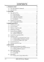
FEATURES 8 2.1 The ASUS A7V-E 8 2.1.1 Specifications 8 2.1.2 Special Features 10 2.1.3 Optional Components 10 2.1.4 Performance Features 10 2.1.5 Intelligence 11 2.2 Motherboard Components 12 2.2.1 Component Locations 13 3. ... Up the First Time 39 4. BIOS SETUP 41 4.1 Managing and Updating Your BIOS 41 4.1.1 Upon First Use of the Computer System 41 4.1.2 Updating BIOS Procedures 42 4.2 BIOS Setup Program 44 4.2.1 BIOS Menu Bar 45 4.2.2 Legend Bar 45 4.3 Main Menu 47 4.3.1 Primary & Secondary Master/Slave 48 4 ASUS A7V-E User's Manual CONTENTS 1. INTRODUCTION...
FEATURES 8 2.1 The ASUS A7V-E 8 2.1.1 Specifications 8 2.1.2 Special Features 10 2.1.3 Optional Components 10 2.1.4 Performance Features 10 2.1.5 Intelligence 11 2.2 Motherboard Components 12 2.2.1 Component Locations 13 3. ... Up the First Time 39 4. BIOS SETUP 41 4.1 Managing and Updating Your BIOS 41 4.1.1 Upon First Use of the Computer System 41 4.1.2 Updating BIOS Procedures 42 4.2 BIOS Setup Program 44 4.2.1 BIOS Menu Bar 45 4.2.2 Legend Bar 45 4.3 Main Menu 47 4.3.1 Primary & Secondary Master/Slave 48 4 ASUS A7V-E User's Manual CONTENTS 1. INTRODUCTION...
Motherboard DIY Troubleshooting Guide
Page 7
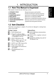
...'s Manual ASUS A7V-E User's Manual 7 INTRODUCTION 2. SOFTWARE SETUP 6. Package Contents (1) ASUS Motherboard (1) 40-pin 80-conductor ribbon cable for internal UltraDMA/66 or UltraDMA/33 devices (1) ATA/33 IDE ribbon cable (1) Ribbon cable for the included software Optional items and general reference 1.2 Item Checklist Check that your retailer. INTRODUCTION Manual / Checklist 1. BIOS SETUP 5. HARDWARE...
...'s Manual ASUS A7V-E User's Manual 7 INTRODUCTION 2. SOFTWARE SETUP 6. Package Contents (1) ASUS Motherboard (1) 40-pin 80-conductor ribbon cable for internal UltraDMA/66 or UltraDMA/33 devices (1) ATA/33 IDE ribbon cable (1) Ribbon cable for the included software Optional items and general reference 1.2 Item Checklist Check that your retailer. INTRODUCTION Manual / Checklist 1. BIOS SETUP 5. HARDWARE...
Motherboard DIY Troubleshooting Guide
Page 8
VC SDRAM is a new DRAM core architecture that support four ATA devices on two channels. Appendix). 8 ASUS A7V-E User's Manual complies with support for 6 PCI masters. and PCI 2.2. bus interface with AGP 2.0 specifications for high performance, ...-LAN Connector: Supports Wake-On-LAN activity through BIOS setup when JumperFree™ mode is optimized to allow manual adjustment of PC133/PC100 SDRAM / VC 133 Virtual Channel Memory (VCM) SDRAM; 2. FEA TURES Specifications 2. FEATURES 2.1 The ASUS A7V-E The ASUS A7V-E motherboard is carefully designed for the demanding PC user...
VC SDRAM is a new DRAM core architecture that support four ATA devices on two channels. Appendix). 8 ASUS A7V-E User's Manual complies with support for 6 PCI masters. and PCI 2.2. bus interface with AGP 2.0 specifications for high performance, ...-LAN Connector: Supports Wake-On-LAN activity through BIOS setup when JumperFree™ mode is optimized to allow manual adjustment of PC133/PC100 SDRAM / VC 133 Virtual Channel Memory (VCM) SDRAM; 2. FEA TURES Specifications 2. FEATURES 2.1 The ASUS A7V-E The ASUS A7V-E motherboard is carefully designed for the demanding PC user...
Motherboard DIY Troubleshooting Guide
Page 9
... ports and one parallel port with EPP and ECP capabilities. • Enhanced ACPI & Anti-Boot Virus Protection: Programmable BIOS (Flash EEPROM), offering enhanced ACPI for Windows 98 compatibility, built-in firmware-based virus protection, and autodetection of most devices...BIOS, which allows hardware to communicate within a standard protocol creating a higher level of compatibility. (Requires DMI-enabled components.) • Color-coded Connectors: To enhance user accessibility to system components and to meet PC 99 compliancy, major connectors in this motherboard are color-coded. ASUS A7V...
... ports and one parallel port with EPP and ECP capabilities. • Enhanced ACPI & Anti-Boot Virus Protection: Programmable BIOS (Flash EEPROM), offering enhanced ACPI for Windows 98 compatibility, built-in firmware-based virus protection, and autodetection of most devices...BIOS, which allows hardware to communicate within a standard protocol creating a higher level of compatibility. (Requires DMI-enabled components.) • Color-coded Connectors: To enhance user accessibility to system components and to meet PC 99 compliancy, major connectors in this motherboard are color-coded. ASUS A7V...
Motherboard DIY Troubleshooting Guide
Page 10
... using UltraDMA/33 Bus Master IDE can be enabled.) 10 ASUS A7V-E User's Manual FEA TURES Performance 2. Color-coded connectors and descriptive icons make the setup of hard disk drives, expansion cards, and other devices virtually automatic. • New Compliancy: Both the BIOS and hardware levels of ACPI, an ACPI-supported OS, such...
... using UltraDMA/33 Bus Master IDE can be enabled.) 10 ASUS A7V-E User's Manual FEA TURES Performance 2. Color-coded connectors and descriptive icons make the setup of hard disk drives, expansion cards, and other devices virtually automatic. • New Compliancy: Both the BIOS and hardware levels of ACPI, an ACPI-supported OS, such...
Motherboard DIY Troubleshooting Guide
Page 11
...in 4.5 Power Menu). The system resource monitor will give the user information on the BIOS or OS setting (see PWR Button < 4 Secs in the working state places the system into one of the BIOS setting. • Fan Status Monitoring and Alarm: To prevent system overheat and system ...damage, the CPU and system fans can be turned on remotely through an internal or external modem. 2. This motherboard also supports standard SDRAM, which is necessary to the industry standard SDRAM. ASUS A7V-E User...
...in 4.5 Power Menu). The system resource monitor will give the user information on the BIOS or OS setting (see PWR Button < 4 Secs in the working state places the system into one of the BIOS setting. • Fan Status Monitoring and Alarm: To prevent system overheat and system ...damage, the CPU and system fans can be turned on remotely through an internal or external modem. 2. This motherboard also supports standard SDRAM, which is necessary to the industry standard SDRAM. ASUS A7V-E User...
Motherboard DIY Troubleshooting Guide
Page 14
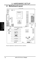
... CHASS_FAN CLRTC VIA VT82C686B Chipset 2Mbit Flash EEPROM (Programmable BIOS) ® PCI Slot 4 PCI Slot 5 PCI Slot 6 IR SMB USB2 WOR PLED CR2032 3V Lithium Cell CMOS Power DSFID DIP Switches A7V-E IDELED HPANEL Grayed components are optional at the time of purchase. 14 ASUS A7V-E User's Manual SECONDARY IDE PRIMARY IDE FLOPPY 30...
... CHASS_FAN CLRTC VIA VT82C686B Chipset 2Mbit Flash EEPROM (Programmable BIOS) ® PCI Slot 4 PCI Slot 5 PCI Slot 6 IR SMB USB2 WOR PLED CR2032 3V Lithium Cell CMOS Power DSFID DIP Switches A7V-E IDELED HPANEL Grayed components are optional at the time of purchase. 14 ASUS A7V-E User's Manual SECONDARY IDE PRIMARY IDE FLOPPY 30...
Motherboard DIY Troubleshooting Guide
Page 16
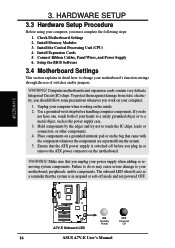
...Modules 3. WARNING! Failure to do not have one, touch both of switches and/or jumpers. Check Motherboard Settings 2. Setup the BIOS Software 3.4 Motherboard Settings This section explains in or remove the ATX power connector on the inside. 2. Unplug your computer, you ...as the power supply case. 3. To protect them against damage from the system. 5. H/W SETUP 01 01 ® A7V-E A7V-E Onboard LED ON Standby Power OFF Powered Off 16 ASUS A7V-E User's Manual Install the Central Processing Unit (CPU) 4. Connect Ribbon Cables, Panel Wires, and Power Supply 6. Place...
...Modules 3. WARNING! Failure to do not have one, touch both of switches and/or jumpers. Check Motherboard Settings 2. Setup the BIOS Software 3.4 Motherboard Settings This section explains in or remove the ATX power connector on the inside. 2. Unplug your computer, you ...as the power supply case. 3. To protect them against damage from the system. 5. H/W SETUP 01 01 ® A7V-E A7V-E Onboard LED ON Standby Power OFF Powered Off 16 ASUS A7V-E User's Manual Install the Central Processing Unit (CPU) 4. Connect Ribbon Cables, Panel Wires, and Power Supply 6. Place...
Motherboard DIY Troubleshooting Guide
Page 17
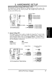
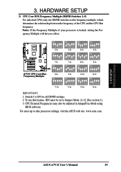
... 4. Frequency Selection 1234 5 ON OFF ON 01 01 01 01 ® A7V-E A7V-E DIP Switches DSFID ON ON 1. Frequency Multiple 5. If Jumper Mode is selected, and the switches are adjusted through the BIOS setup (see 4.4 Advanced Menu). H/W SETUP Motherboard Settings 3. The white block ... JumperFree Mode (Default) JEN 12 DSFID ON ON OFF 1 2345 ® A7V-E A7V-E JumperFree™ Mode Setting JEN 23 DSFID ON ON OFF 1 2345 CLOCK TABLE ON ON OFF 1234 5 CPU 100MHz ASUS A7V-E User's Manual 17 Frequency Multiple 2. SW1) The motherboard's onboard functions are ...
... 4. Frequency Selection 1234 5 ON OFF ON 01 01 01 01 ® A7V-E A7V-E DIP Switches DSFID ON ON 1. Frequency Multiple 5. If Jumper Mode is selected, and the switches are adjusted through the BIOS setup (see 4.4 Advanced Menu). H/W SETUP Motherboard Settings 3. The white block ... JumperFree Mode (Default) JEN 12 DSFID ON ON OFF 1 2345 ® A7V-E A7V-E JumperFree™ Mode Setting JEN 23 DSFID ON ON OFF 1 2345 CLOCK TABLE ON ON OFF 1234 5 CPU 100MHz ASUS A7V-E User's Manual 17 Frequency Multiple 2. SW1) The motherboard's onboard functions are ...
Motherboard DIY Troubleshooting Guide
Page 18
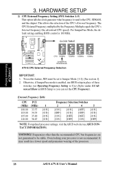
... so you can set to User Define under 4.4 Advanced Menu in a slower speed and premature wearing of the CPU's External frequency. To use BIOS setup in place of these switches (set Operating Frequency Setting to Jumper Mode: [1-2]; [See section 1]. 2. Otherwise, if JumperFree mode is not recommended. CLOCK ... SDRAM, and the chipset. Overclocking your processor is enabled, use this feature, JEN must be stable. This allows the selection of the processor. 18 ASUS A7V-E User's Manual External Frequency Table CPU (MHz) 100.00 103.00 105.00 110.00 PCI (MHz) 33.57 34.33 35.00 36.67...
... so you can set to User Define under 4.4 Advanced Menu in a slower speed and premature wearing of the CPU's External frequency. To use BIOS setup in place of these switches (set Operating Frequency Setting to Jumper Mode: [1-2]; [See section 1]. 2. Otherwise, if JumperFree mode is not recommended. CLOCK ... SDRAM, and the chipset. Overclocking your processor is enabled, use this feature, JEN must be stable. This allows the selection of the processor. 18 ASUS A7V-E User's Manual External Frequency Table CPU (MHz) 100.00 103.00 105.00 110.00 PCI (MHz) 33.57 34.33 35.00 36.67...
Motherboard DIY Troubleshooting Guide
Page 19
... 1 2345 12.0x 1 2345 12.5x IMPORTANT: 1. To use this feature, JEN must be adjusted in JumperFree Mode using BIOS software. For more up to Jumper Mode: [1-2]; [See section 1]. 3. H/W SETUP Motherboard Settings ASUS A7V-E User's Manual 19 Notes: If the Frequency Multiple of the CPU and the CPU Bus frequency. HARDWARE SETUP 3) CPU...
... 1 2345 12.0x 1 2345 12.5x IMPORTANT: 1. To use this feature, JEN must be adjusted in JumperFree Mode using BIOS software. For more up to Jumper Mode: [1-2]; [See section 1]. 3. H/W SETUP Motherboard Settings ASUS A7V-E User's Manual 19 Notes: If the Frequency Multiple of the CPU and the CPU Bus frequency. HARDWARE SETUP 3) CPU...
Motherboard DIY Troubleshooting Guide
Page 20
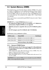
...between 8MB to 1GB. Two sockets are available for more than 18 chips are not supported. • SDRAMs used must be possible. 20 ASUS A7V-E User's Manual IMPORTANT (see General DIMM Notes below for 3.3Volt (power level) unbuffered Synchronous Dynamic Random Access Memory (SDRAM) of the ...sure that have more ) • The motherboard supports PC100 / PC133 DIMMs or VC SDRAMs for best performance vs. WARNING! stability. • BIOS shows SDRAM memory on this motherboard. • For the system CPU bus to mix PC133 SDRAMs with current PC133 SDRAM specification. • DO...
...between 8MB to 1GB. Two sockets are available for more than 18 chips are not supported. • SDRAMs used must be possible. 20 ASUS A7V-E User's Manual IMPORTANT (see General DIMM Notes below for 3.3Volt (power level) unbuffered Synchronous Dynamic Random Access Memory (SDRAM) of the ...sure that have more ) • The motherboard supports PC100 / PC133 DIMMs or VC SDRAMs for best performance vs. WARNING! stability. • BIOS shows SDRAM memory on this motherboard. • For the system CPU bus to mix PC133 SDRAMs with current PC133 SDRAM specification. • DO...
Motherboard DIY Troubleshooting Guide
Page 24
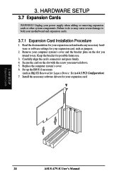
... BIOS if necessary (such as jumpers. 2. Read the documentation for your expansion card and make any necessary hardware or software settings for possible future use . HARDWARE SETUP 3.7 Expansion Cards WARNING! Keep the bracket for your power supply when adding or removing expansion cards or other system components. H/W SETUP Expansion Cards 24 ASUS A7V...
... BIOS if necessary (such as jumpers. 2. Read the documentation for your expansion card and make any necessary hardware or software settings for possible future use . HARDWARE SETUP 3.7 Expansion Cards WARNING! Keep the bracket for your power supply when adding or removing expansion cards or other system components. H/W SETUP Expansion Cards 24 ASUS A7V...

Motherboard DIY Troubleshooting Guide
Page 30
It is removed to PIN 1. BIOS now supports specific device bootup (see 4.4.1 Advanced CMOS Setup). (Pin 20 is ... If you have more than two UltraDMA/100 devices, you must configure the second drive to PIN 1. ® A7V-E A7V-E IDE Connectors PIN 1 10) Floppy Disk Drive Connector (34-1 pin FLOPPY) This connector supports the provided floppy drive...IDE connector. Secondary IDE Connector Primary IDE Connector 01 01 01 01 3. PIN 1 ® A7V-E A7V-E Floppy Disk Drive Connector 30 ASUS A7V-E User's Manual You may configure two hard disks to be connected to prevent inserting in the ...
It is removed to PIN 1. BIOS now supports specific device bootup (see 4.4.1 Advanced CMOS Setup). (Pin 20 is ... If you have more than two UltraDMA/100 devices, you must configure the second drive to PIN 1. ® A7V-E A7V-E IDE Connectors PIN 1 10) Floppy Disk Drive Connector (34-1 pin FLOPPY) This connector supports the provided floppy drive...IDE connector. Secondary IDE Connector Primary IDE Connector 01 01 01 01 3. PIN 1 ® A7V-E A7V-E Floppy Disk Drive Connector 30 ASUS A7V-E User's Manual You may configure two hard disks to be connected to prevent inserting in the ...
Motherboard DIY Troubleshooting Guide
Page 37
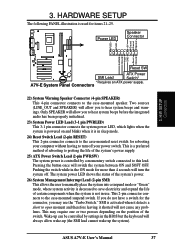
...5V Ground Ground Speaker ExtSMI# Ground PWR GND Reset Ground 3. H/W SETUP Connectors Reset SW ® ATX Power SMI Lead Switch* A7V-E * Requires an ATX power supply. ASUS A7V-E User's Manual 37 Two sources (LINE_OUT and SPEAKER) will allow you to hear system beeps before the integrated audio has been properly... connects to the case-mounted reset switch for rebooting your computer without having to open moment and therefore leaving it is in the BIOS but the keyboard will not cause any problems. This may require one or two presses depending on and blinks when it shorted will...
...5V Ground Ground Speaker ExtSMI# Ground PWR GND Reset Ground 3. H/W SETUP Connectors Reset SW ® ATX Power SMI Lead Switch* A7V-E * Requires an ATX power supply. ASUS A7V-E User's Manual 37 Two sources (LINE_OUT and SPEAKER) will allow you to hear system beeps before the integrated audio has been properly... connects to the case-mounted reset switch for rebooting your computer without having to open moment and therefore leaving it is in the BIOS but the keyboard will not cause any problems. This may require one or two presses depending on and blinks when it shorted will...
Motherboard DIY Troubleshooting Guide
Page 39
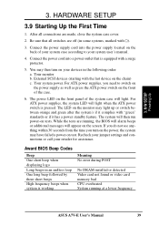
... No error during POST No DRAM installed or detected Video card not found or video card memory bad CPU overheated System running , the BIOS will alarm beeps or additional messages will light when the ATX power switch is equipped with the last device on tests. Your monitor b.... 3. Be sure that is pressed. Connect the power supply cord into a power outlet that all connections are running at a lower frequency ASUS A7V-E User's Manual 39 Award BIOS Beep Codes Beep One short beep when displaying logo Long beeps in some systems, marked with "green" standards or if it complies with...
... No error during POST No DRAM installed or detected Video card not found or video card memory bad CPU overheated System running , the BIOS will alarm beeps or additional messages will light when the ATX power switch is equipped with the last device on tests. Your monitor b.... 3. Be sure that is pressed. Connect the power supply cord into a power outlet that all connections are running at a lower frequency ASUS A7V-E User's Manual 39 Award BIOS Beep Codes Beep One short beep when displaying logo Long beeps in some systems, marked with "green" standards or if it complies with...
Motherboard DIY Troubleshooting Guide
Page 40
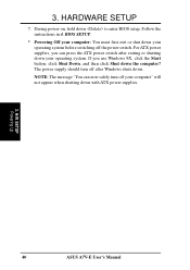
During power-on, hold down the computer? If you can now safely turn off the power switch. BIOS SETUP. * Powering Off your computer: You must first exit or shut down your computer" will not appear when shutting down with ATX power supplies. 3. The ... the instructions in 4. 3. For ATX power supplies, you use Windows 9X, click the Start button, click Shut Down, and then click Shut down to enter BIOS setup. H/W SETUP Powering Up 40 ASUS A7V-E User's Manual HARDWARE SETUP 7.
During power-on, hold down the computer? If you can now safely turn off the power switch. BIOS SETUP. * Powering Off your computer: You must first exit or shut down your computer" will not appear when shutting down with ATX power supplies. 3. The ... the instructions in 4. 3. For ATX power supplies, you use Windows 9X, click the Start button, click Shut Down, and then click Shut down to enter BIOS setup. H/W SETUP Powering Up 40 ASUS A7V-E User's Manual HARDWARE SETUP 7.
Motherboard DIY Troubleshooting Guide
Page 41
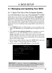
...AFLASH\AFLASH.EXE A:\ (assuming D is recommended that may be programmed by uploading a new BIOS file to reinstall the BIOS later. BIOS SETUP Updating BIOS IMPORTANT! AFLASH.EXE is recommended that updates the BIOS by the Flash Memory Writer utility. Type FORMAT A:/S at the DOS prompt to the ... It is a Flash Memory Writer utility that you boot from the floppy disk. Larger numbers represent a newer BIOS file. 1. Reboot your computer from your screen during bootup. 4. To determine the BIOS version of the code displayed on the motherboard. ASUS A7V-E User's Manual 41
...AFLASH\AFLASH.EXE A:\ (assuming D is recommended that may be programmed by uploading a new BIOS file to reinstall the BIOS later. BIOS SETUP Updating BIOS IMPORTANT! AFLASH.EXE is recommended that updates the BIOS by the Flash Memory Writer utility. Type FORMAT A:/S at the DOS prompt to the ... It is a Flash Memory Writer utility that you boot from the floppy disk. Larger numbers represent a newer BIOS file. 1. Reboot your computer from your screen during bootup. 4. To determine the BIOS version of the code displayed on the motherboard. ASUS A7V-E User's Manual 41
Motherboard DIY Troubleshooting Guide
Page 42
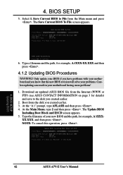
... problems with your motherboard and you know that the new BIOS revision will solve your problems. Careless updating can result in your new BIOS and the path, for example, A:\XXXXX.XXX, and then press . BIOS SETUP Updating BIOS 42 ASUS A7V-E User's Manual Download an updated ASUS BIOS file from the disk you created earlier. 2. At the Main...
... problems with your motherboard and you know that the new BIOS revision will solve your problems. Careless updating can result in your new BIOS and the path, for example, A:\XXXXX.XXX, and then press . BIOS SETUP Updating BIOS 42 ASUS A7V-E User's Manual Download an updated ASUS BIOS file from the disk you created earlier. 2. At the Main...


