Motherboard DIY Troubleshooting Guide
Page 4
... Bar 45 4.2.2 Legend Bar 45 4.3 Main Menu 47 4.3.1 Primary & Secondary Master/Slave 48 4 ASUS A7V-E User's Manual CONTENTS 1. HARDWARE SETUP 14 3.1 Motherboard Layout 14 3.2 Layout Contents 15 3.3 Hardware Setup Procedure 16 3.4 Motherboard Settings 16 3.5 System Memory (DIMM 20 3.5.1 General DIMM Notes 20 3.5.2 Memory Installation 21 3.6 Central Processing Unit (CPU 23 3.7 Expansion Cards 24 3.7.1 Expansion Card...
... Bar 45 4.2.2 Legend Bar 45 4.3 Main Menu 47 4.3.1 Primary & Secondary Master/Slave 48 4 ASUS A7V-E User's Manual CONTENTS 1. HARDWARE SETUP 14 3.1 Motherboard Layout 14 3.2 Layout Contents 15 3.3 Hardware Setup Procedure 16 3.4 Motherboard Settings 16 3.5 System Memory (DIMM 20 3.5.1 General DIMM Notes 20 3.5.2 Memory Installation 21 3.6 Central Processing Unit (CPU 23 3.7 Expansion Cards 24 3.7.1 Expansion Card...
Motherboard DIY Troubleshooting Guide
Page 5
SOFTWARE REFERENCE 79 6.1 ASUS PC Probe 79 6.3 CyberLink PowerDVD 84 6.2 CyberLink PowerPlayer SE 85 6.4 CyberLink VideoLive Mail 86 7. CONTENTS 4.3.2 Keyboard Features 51 4.4 Advanced Menu 53 4.4.1 Chip Configuration 56 4.4.2 I/O Device ... Menu 67 4.5.1 Power Up Control 69 4.5.2 Hardware Monitor 70 4.6 Boot Menu 71 4.7 Exit Menu 73 5. APPENDIX 89 7.1 PCI-L101 Fast Ethernet Card 89 7.2 Glossary 91 ASUS A7V-E User's Manual 5 SOFTWARE SETUP 75 5.1 Install Operating System 75 5.2 Start Windows 75 5.3 A7V-E Series Motherboard Support CD 76 6.
SOFTWARE REFERENCE 79 6.1 ASUS PC Probe 79 6.3 CyberLink PowerDVD 84 6.2 CyberLink PowerPlayer SE 85 6.4 CyberLink VideoLive Mail 86 7. CONTENTS 4.3.2 Keyboard Features 51 4.4 Advanced Menu 53 4.4.1 Chip Configuration 56 4.4.2 I/O Device ... Menu 67 4.5.1 Power Up Control 69 4.5.2 Hardware Monitor 70 4.6 Boot Menu 71 4.7 Exit Menu 73 5. APPENDIX 89 7.1 PCI-L101 Fast Ethernet Card 89 7.2 Glossary 91 ASUS A7V-E User's Manual 5 SOFTWARE SETUP 75 5.1 Install Operating System 75 5.2 Start Windows 75 5.3 A7V-E Series Motherboard Support CD 76 6.
Motherboard DIY Troubleshooting Guide
Page 10
... I/O Device Configuration in the OS, PCs can handle rates up to make identification easy as Windows 98 must be enabled.) 10 ASUS A7V-E User's Manual Color-coded connectors and descriptive icons make the setup of hard disk drives, expansion cards, and other devices virtually ...-conductor cable to 100MB/s. 2. FEA TURES Performance 2. To fully utilize the benefits of this motherboard meet the stringent requirements for UltraDMA/100 doubles the data transfer rate to be used. • Easy Installation: Incorporates BIOS that support OS Direct Power Management (OSPM) functionality.
... I/O Device Configuration in the OS, PCs can handle rates up to make identification easy as Windows 98 must be enabled.) 10 ASUS A7V-E User's Manual Color-coded connectors and descriptive icons make the setup of hard disk drives, expansion cards, and other devices virtually ...-conductor cable to 100MB/s. 2. FEA TURES Performance 2. To fully utilize the benefits of this motherboard meet the stringent requirements for UltraDMA/100 doubles the data transfer rate to be used. • Easy Installation: Incorporates BIOS that support OS Direct Power Management (OSPM) functionality.
Motherboard DIY Troubleshooting Guide
Page 16
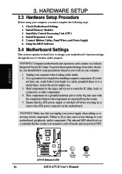
... 6. To protect them against damage from the system. 5. Install Expansion Cards 5. Computer motherboards and expansion cards contain very delicate Integrated Circuit (IC) chips. WARNING! H/W SETUP 01 01 ® A7V-E A7V-E Onboard LED ON Standby Power OFF Powered Off 16 ASUS A7V-E User's Manual Setup the BIOS Software 3.4 Motherboard Settings This section explains in detail how to change...
... 6. To protect them against damage from the system. 5. Install Expansion Cards 5. Computer motherboards and expansion cards contain very delicate Integrated Circuit (IC) chips. WARNING! H/W SETUP 01 01 ® A7V-E A7V-E Onboard LED ON Standby Power OFF Powered Off 16 ASUS A7V-E User's Manual Setup the BIOS Software 3.4 Motherboard Settings This section explains in detail how to change...
Motherboard DIY Troubleshooting Guide
Page 20
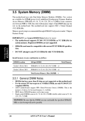
...256, 512MB. Be sure that have more ) • The motherboard supports PC100 / PC133 DIMMs or VC SDRAMs for system memory. Registered DIMMs are not supported. • SDRAMs used must be possible. 20 ASUS A7V-E User's Manual WARNING! double-sided come in any combination as... the DIMM you use only PC100-/PC133- Two sockets are not supported on the motherboard. One side (with VCM SDRAMs. Install memory in 16, 32, 64,128, 256MB; compliant DIMMs. • ASUS motherboards support SPD (Serial Presence Detect) DIMMs. This is recommended through SDRAM Configuration under ...
...256, 512MB. Be sure that have more ) • The motherboard supports PC100 / PC133 DIMMs or VC SDRAMs for system memory. Registered DIMMs are not supported. • SDRAMs used must be possible. 20 ASUS A7V-E User's Manual WARNING! double-sided come in any combination as... the DIMM you use only PC100-/PC133- Two sockets are not supported on the motherboard. One side (with VCM SDRAMs. Install memory in 16, 32, 64,128, 256MB; compliant DIMMs. • ASUS motherboards support SPD (Serial Presence Detect) DIMMs. This is recommended through SDRAM Configuration under ...
Motherboard DIY Troubleshooting Guide
Page 21
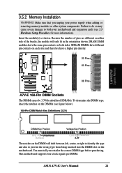
.... Insert the module(s) as shown. This motherboard supports four clock signals per DIMM. ASUS A7V-E User's Manual 21 DRAM SIMM modules have a higher pin density. 20 Pins 60 Pins 88 Pins ® A7V-E A7V-E 168-Pin DIMM Sockets The DIMMs must ...tell your power supply when adding or removing memory modules or other system components. Because the number of pins are different on the motherboard. 01 01 3.5.2 Memory Installation...
.... Insert the module(s) as shown. This motherboard supports four clock signals per DIMM. ASUS A7V-E User's Manual 21 DRAM SIMM modules have a higher pin density. 20 Pins 60 Pins 88 Pins ® A7V-E A7V-E 168-Pin DIMM Sockets The DIMMs must ...tell your power supply when adding or removing memory modules or other system components. Because the number of pins are different on the motherboard. 01 01 3.5.2 Memory Installation...
Motherboard DIY Troubleshooting Guide
Page 23
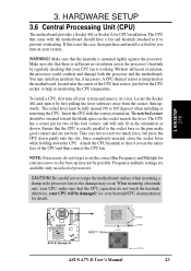
.... CAUTION! If this is working. WARNING! Without sufficient circulation, the processor could overheat and damage both the processor and the motherboard. To install a CPU, first turn on unlocked processors. The socket lever must be possible. Frequency multiple settings are not bent. Take care...your CPU, make good contact and are available only on your system. H/W SETUP CPU 01 01 ® A7V-E A7V-E Socket A AMD™ Athlon LOCK BLANK LEVER NOTCH ASUS A7V-E User's Manual 23 NOTE: If necessary, do not touch the heatsink; When mounting a heatsink onto your ...
.... CAUTION! If this is working. WARNING! Without sufficient circulation, the processor could overheat and damage both the processor and the motherboard. To install a CPU, first turn on unlocked processors. The socket lever must be possible. Frequency multiple settings are not bent. Take care...your CPU, make good contact and are available only on your system. H/W SETUP CPU 01 01 ® A7V-E A7V-E Socket A AMD™ Athlon LOCK BLANK LEVER NOTCH ASUS A7V-E User's Manual 23 NOTE: If necessary, do not touch the heatsink; When mounting a heatsink onto your ...
Motherboard DIY Troubleshooting Guide
Page 24
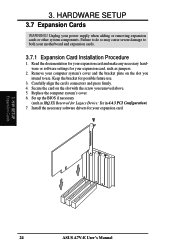
... settings for Legacy Device: Yes in 4.4.3 PCI Configuration) 7. Carefully align the card's connectors and press firmly. 4. H/W SETUP Expansion Cards 24 ASUS A7V-E User's Manual Secure the card on the slot you removed above. 5. Set up the BIOS if necessary (such as jumpers. 2. Failure to...supply when adding or removing expansion cards or other system components. Replace the computer system's cover. 6. Unplug your motherboard and expansion cards. 3.7.1 Expansion Card Installation Procedure 1. 3. HARDWARE SETUP 3.7 Expansion Cards WARNING! Remove your expansion card. 3.
... settings for Legacy Device: Yes in 4.4.3 PCI Configuration) 7. Carefully align the card's connectors and press firmly. 4. H/W SETUP Expansion Cards 24 ASUS A7V-E User's Manual Secure the card on the slot you removed above. 5. Set up the BIOS if necessary (such as jumpers. 2. Failure to...supply when adding or removing expansion cards or other system components. Replace the computer system's cover. 6. Unplug your motherboard and expansion cards. 3.7.1 Expansion Card Installation Procedure 1. 3. HARDWARE SETUP 3.7 Expansion Cards WARNING! Remove your expansion card. 3.

Motherboard DIY Troubleshooting Guide
Page 27
...PS/2 plug (mini DIN). IDE ribbon cable must be connected with the second drive connector no more than 15 cm (6 in the Motherboard Layout. This connector will direct IRQ12 to the PS/2 mouse if one is detected. Placing jumper caps over these connector pins will ...PS/2 Mouse (6-pin Female) 3. PS/2 Keyboard (6-pin Female) ASUS A7V-E User's Manual 27 HARDWARE SETUP 3.8 External Connectors WARNING! IMPORTANT: Ribbon cables should always be less than 46 cm (18 in 4.4 Advanced Menu. Check the connectors before installation because there may be on the opposite side on the connectors. If...
...PS/2 plug (mini DIN). IDE ribbon cable must be connected with the second drive connector no more than 15 cm (6 in the Motherboard Layout. This connector will direct IRQ12 to the PS/2 mouse if one is detected. Placing jumper caps over these connector pins will ...PS/2 Mouse (6-pin Female) 3. PS/2 Keyboard (6-pin Female) ASUS A7V-E User's Manual 27 HARDWARE SETUP 3.8 External Connectors WARNING! IMPORTANT: Ribbon cables should always be less than 46 cm (18 in 4.4 Advanced Menu. Check the connectors before installation because there may be on the opposite side on the connectors. If...

Motherboard DIY Troubleshooting Guide
Page 30
Connect the cable's blue connector to the motherboard's primary (recommended) or secondary IDE connector, and then connect ...may configure two hard disks to be connected to prevent inserting in the wrong orienta- If you install two hard disks, you will need to prevent inserting in the wrong orientation when using ribbon cables ...your hard disk documentation for the secondary IDE connector. PIN 1 ® A7V-E A7V-E Floppy Disk Drive Connector 30 ASUS A7V-E User's Manual 3. TIP: You may install one for the primary IDE connector and another UltraDMA/100 cable. Secondary IDE...
Connect the cable's blue connector to the motherboard's primary (recommended) or secondary IDE connector, and then connect ...may configure two hard disks to be connected to prevent inserting in the wrong orienta- If you install two hard disks, you will need to prevent inserting in the wrong orientation when using ribbon cables ...your hard disk documentation for the secondary IDE connector. PIN 1 ® A7V-E A7V-E Floppy Disk Drive Connector 30 ASUS A7V-E User's Manual 3. TIP: You may install one for the primary IDE connector and another UltraDMA/100 cable. Secondary IDE...

Motherboard DIY Troubleshooting Guide
Page 31
... a chassis intrusion monitor/sensor or microswitch. IR 1 Front View Back View ® A7V-E A7V-E Infrared Module Connector IRTX GND IRRX +5V (NC) ASUS A7V-E User's Manual 31 3. CHASSIS Ground Chassis Signal +5Volt 1 (Power Supply Stand By) ® A7V-E A7V-E Chassis Open Alarm Lead +5V IRRX GND IRTX 3. H/W SETUP Connectors 01 01 01...CHASSIS) This requires an external detection mechanism such as shown in Back View and connect a ribbon cable from the module to the motherboard's SIR connector according to select whether UART2 is not used, a jumper cap must be installed (see 7.
... a chassis intrusion monitor/sensor or microswitch. IR 1 Front View Back View ® A7V-E A7V-E Infrared Module Connector IRTX GND IRRX +5V (NC) ASUS A7V-E User's Manual 31 3. CHASSIS Ground Chassis Signal +5Volt 1 (Power Supply Stand By) ® A7V-E A7V-E Chassis Open Alarm Lead +5V IRRX GND IRTX 3. H/W SETUP Connectors 01 01 01...CHASSIS) This requires an external detection mechanism such as shown in Back View and connect a ribbon cable from the module to the motherboard's SIR connector according to select whether UART2 is not used, a jumper cap must be installed (see 7.
Motherboard DIY Troubleshooting Guide
Page 44
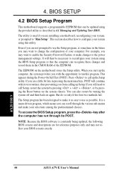
... may want to enable the Security Password Feature or make it as easy to "Run Setup". It is used if you are installing a motherboard, reconfiguring your system using the BIOS Setup program so that can recognize these changes and record them in 4.1 Managing and Updating Your...program, press the key after the computer has run this utility. BIOS SETUP 44 ASUS A7V-E User's Manual But do so only if the first two methods fail. BIOS SETUP 4.2 BIOS Setup Program This motherboard supports a programmable EEPROM that the computer can be updated using this program. The ...
... may want to enable the Security Password Feature or make it as easy to "Run Setup". It is used if you are installing a motherboard, reconfiguring your system using the BIOS Setup program so that can recognize these changes and record them in 4.1 Managing and Updating Your...program, press the key after the computer has run this utility. BIOS SETUP 44 ASUS A7V-E User's Manual But do so only if the first two methods fail. BIOS SETUP 4.2 BIOS Setup Program This motherboard supports a programmable EEPROM that the computer can be updated using this program. The ...
Motherboard DIY Troubleshooting Guide
Page 54
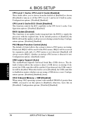
... reserved for the PS/2 mouse. Configuration options: [Enabled] [Auto] USB Legacy Support [Auto] This motherboard supports Universal Serial Bus (USB) devices. When this field is set this on all processors during system ...a PS/2 mouse is disabled no matter whether you are using OS/2 operating systems with installed DRAM of greater than 64MB, you to choose from the default of [Enabled], the ...load the update on [Disabled]. If detected, the USB controller will be enabled. BIOS SETUP 54 ASUS A7V-E User's Manual In the default position of [Enabled] or choose [Disabled] to detect a ...
... reserved for the PS/2 mouse. Configuration options: [Enabled] [Auto] USB Legacy Support [Auto] This motherboard supports Universal Serial Bus (USB) devices. When this field is set this on all processors during system ...a PS/2 mouse is disabled no matter whether you are using OS/2 operating systems with installed DRAM of greater than 64MB, you to choose from the default of [Enabled], the ...load the update on [Disabled]. If detected, the USB controller will be enabled. BIOS SETUP 54 ASUS A7V-E User's Manual In the default position of [Enabled] or choose [Disabled] to detect a ...
Motherboard DIY Troubleshooting Guide
Page 75
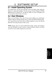
... restart, select No and then follow the setup procedures in this section. S/W SETUP Install OS ASUS A7V-E User's Manual 75 You may not reflect exactly the screen contents displayed on your motherboard, Windows will detect all necessary device drivers. 5. SOFTWARE SETUP 5.1 Install Operating System You should always use any version of Windows 98/2000/ Millenium...
... restart, select No and then follow the setup procedures in this section. S/W SETUP Install OS ASUS A7V-E User's Manual 75 You may not reflect exactly the screen contents displayed on your motherboard, Windows will detect all necessary device drivers. 5. SOFTWARE SETUP 5.1 Install Operating System You should always use any version of Windows 98/2000/ Millenium...
Motherboard DIY Troubleshooting Guide
Page 76
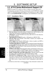
...(TO SEE THE FOLLOWING ITEMS, CLICK RIGHT ARROW ON THE LOWER-RIGHT CORNER OF THE MAIN MENU) 76 ASUS A7V-E User's Manual S/W SETUP Support CD • VIA 4 in 1 drivers: Installs Bus Master PCI IDE Driver, AGP VxD Driver, VIA Chipset Functions Registry, and IRQ Routing Miniport Driver. ... • USB Patch File for AMD K7: Installs a USB update for AMD K7 CPUs. • ASUS PC Probe Vx.xx: Installs a smart utility to change at any time without notice. Updated or other language versions of this motherboard's manual is drive D:). 5.3.1 Installation Menu 5. 5. Refer to the online help for ...
...(TO SEE THE FOLLOWING ITEMS, CLICK RIGHT ARROW ON THE LOWER-RIGHT CORNER OF THE MAIN MENU) 76 ASUS A7V-E User's Manual S/W SETUP Support CD • VIA 4 in 1 drivers: Installs Bus Master PCI IDE Driver, AGP VxD Driver, VIA Chipset Functions Registry, and IRQ Routing Miniport Driver. ... • USB Patch File for AMD K7: Installs a USB update for AMD K7 CPUs. • ASUS PC Probe Vx.xx: Installs a smart utility to change at any time without notice. Updated or other language versions of this motherboard's manual is drive D:). 5.3.1 Installation Menu 5. 5. Refer to the online help for ...

Motherboard DIY Troubleshooting Guide
Page 77
...hardware management features. • ASUS BIOS Flash Utility for LDCM 6.1: (optional) Installs a utility that remotely flashes to a client PC's BIOS software when used in conjunction with Intel LDCM Administrator. • Show Motherboard Information: Allows you to view information about your motherboard, such as product name, ...Exit: Exits the CD installation menu. (TO RETURN TO THE MAIN MENU, CLICK LEFT ARROW ON THE LOWER-RIGHT CORNER OF THE SECONDARY MENU) Additonal CD Content: Flash BIOS writer can be found in the AFLASH folder. 5. 5. S/W SETUP Support CD ASUS A7V-E User's Manual 77
...hardware management features. • ASUS BIOS Flash Utility for LDCM 6.1: (optional) Installs a utility that remotely flashes to a client PC's BIOS software when used in conjunction with Intel LDCM Administrator. • Show Motherboard Information: Allows you to view information about your motherboard, such as product name, ...Exit: Exits the CD installation menu. (TO RETURN TO THE MAIN MENU, CLICK LEFT ARROW ON THE LOWER-RIGHT CORNER OF THE SECONDARY MENU) Additonal CD Content: Flash BIOS writer can be found in the AFLASH folder. 5. 5. S/W SETUP Support CD ASUS A7V-E User's Manual 77


