A55M-A User's Manual
Page 9
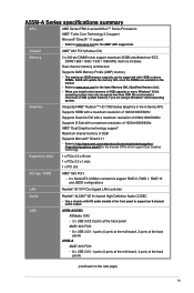
...® Dual Graphics technology support* Maximum shared memory of 2GB Supports Microsoft® DirectX 11 • Refer to support an 8-channel audio output. USB A55M-A/USB3 ASMedia 1042 - 2 x USB 3.0/2.0 ports at the back panel AMD® A55 FCH: - 6 x USB 2.0/1.1 ports (4 ports at the mid-board... PCIe Gigabit LAN controller Audio Realtek® ALC887-VD 8-channel High Definition Audio CODEC • Use a chassis with 16GB or above DIMMs. ASUS will update the memory QVL once the DIMMs are using a Windows® 32-bit operating system. Chipset AMD® A55 FCH (Hudson D2...
...® Dual Graphics technology support* Maximum shared memory of 2GB Supports Microsoft® DirectX 11 • Refer to support an 8-channel audio output. USB A55M-A/USB3 ASMedia 1042 - 2 x USB 3.0/2.0 ports at the back panel AMD® A55 FCH: - 6 x USB 2.0/1.1 ports (4 ports at the mid-board... PCIe Gigabit LAN controller Audio Realtek® ALC887-VD 8-channel High Definition Audio CODEC • Use a chassis with 16GB or above DIMMs. ASUS will update the memory QVL once the DIMMs are using a Windows® 32-bit operating system. Chipset AMD® A55 FCH (Hudson D2...
A55M-A User's Manual
Page 10
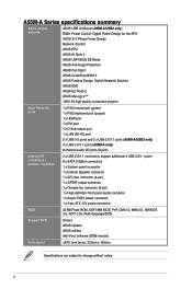
A55M-A Series specifications summary ASUS unique features ASUS USB 3.0 Boost (A55M-A/USB3 only) DIGI+ Power Control: Digital Power Design for the APU ASUS 3+2 Phase Power Design Network iControl ASUS EPU ASUS AI Suite II ASUS UEFI BIOS EZ Mode ASUS Anti-Surge Protection ASUS Fan Xpert ASUS CrashFree BIOS 3 ASUS Fanless Design: Stylish Heatsink Solution ASUS ESD ASUS EZ Flash 2 ASUS MyLogo 2™ 100% All high-quality...
A55M-A Series specifications summary ASUS unique features ASUS USB 3.0 Boost (A55M-A/USB3 only) DIGI+ Power Control: Digital Power Design for the APU ASUS 3+2 Phase Power Design Network iControl ASUS EPU ASUS AI Suite II ASUS UEFI BIOS EZ Mode ASUS Anti-Surge Protection ASUS Fan Xpert ASUS CrashFree BIOS 3 ASUS Fanless Design: Stylish Heatsink Solution ASUS ESD ASUS EZ Flash 2 ASUS MyLogo 2™ 100% All high-quality...
A55M-A User's Manual
Page 11
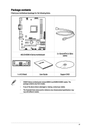
...240-pin module) DDR3 DIMM_B1 (64bit, 240-pin module) SOCKET FM2 DVI_VGA USB1112 LAN1_USB12 ASM 1042 AUDIO KB_USBWB A55M-A/USB3 PCIEX16 RTL 8111F PCIEX1_1 BATTERY Super I/O PCI1 SB_PWR ALC 887 SPDIF_OUT AAFP USBPWF USB56 USB34 AMD® A55 SATA6G_5...SATA6G_3 SATA6G_4 SATA6G_1 SATA6G_2 32Mb BIOS CLRTC SPEAKER F_PANEL EATXPWR ASUS A55M-A Series motherboard User Guide 2 x Serial ATA 3.0 Gb/s cables 1 x I/O Shield User Guide Support DVD • A55M-A Series motherboards include A55M-A and A55M-A/USB3 models. Actual product specifications may vary with different models....
...240-pin module) DDR3 DIMM_B1 (64bit, 240-pin module) SOCKET FM2 DVI_VGA USB1112 LAN1_USB12 ASM 1042 AUDIO KB_USBWB A55M-A/USB3 PCIEX16 RTL 8111F PCIEX1_1 BATTERY Super I/O PCI1 SB_PWR ALC 887 SPDIF_OUT AAFP USBPWF USB56 USB34 AMD® A55 SATA6G_5...SATA6G_3 SATA6G_4 SATA6G_1 SATA6G_2 32Mb BIOS CLRTC SPEAKER F_PANEL EATXPWR ASUS A55M-A Series motherboard User Guide 2 x Serial ATA 3.0 Gb/s cables 1 x I/O Shield User Guide Support DVD • A55M-A Series motherboards include A55M-A and A55M-A/USB3 models. Actual product specifications may vary with different models....
A55M-A User's Manual
Page 15
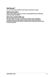
ASUS MyLogo2™ Turn your favorite photos into 256-color boot logos to an already impressive USB 3.0 transfer speed. ASUS software automatically accelerates data speeds for compatible USB 3.0 peripherals without the need for any user interaction. ASUS A55M-A Series 1-3 USB 3.0 Boost (A55M-A/USB3 only) With USB 3.0 Boost technology, a USB device's transmission speed is significantly increased, adding to personalize your system. ASUS CrashFree BIOS 3 ASUS CrashFree BIOS 3 allows you to restore a corrupted BIOS file from a USB storage device that contains the BIOS file.
ASUS MyLogo2™ Turn your favorite photos into 256-color boot logos to an already impressive USB 3.0 transfer speed. ASUS software automatically accelerates data speeds for compatible USB 3.0 peripherals without the need for any user interaction. ASUS A55M-A Series 1-3 USB 3.0 Boost (A55M-A/USB3 only) With USB 3.0 Boost technology, a USB device's transmission speed is significantly increased, adding to personalize your system. ASUS CrashFree BIOS 3 ASUS CrashFree BIOS 3 allows you to restore a corrupted BIOS file from a USB storage device that contains the BIOS file.
A55M-A User's Manual
Page 17
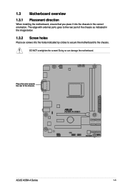
The edge with external ports goes to the chassis. A55M-A/USB3 ASUS A55M-A Series 1-5 DO NOT overtighten the screws! Doing so can damage the motherboard. Place this side towards the rear of the chassis as indicated in the correct orientation. 1.3 Motherboard overview 1.3.1 Placement direction When installing the motherboard, ensure that you place it into the chassis in the image below. 1.3.2 Screw holes Place six screws into the holes indicated by circles to secure the motherboard to the rear part of the chassis.
The edge with external ports goes to the chassis. A55M-A/USB3 ASUS A55M-A Series 1-5 DO NOT overtighten the screws! Doing so can damage the motherboard. Place this side towards the rear of the chassis as indicated in the correct orientation. 1.3 Motherboard overview 1.3.1 Placement direction When installing the motherboard, ensure that you place it into the chassis in the image below. 1.3.2 Screw holes Place six screws into the holes indicated by circles to secure the motherboard to the rear part of the chassis.

A55M-A User's Manual
Page 19
CPU fan connector (4-pin CPU_FAN) and Chassis fan connector (3-pin CHA_FAN) 5. DDR3 DIMM slots 6. The APU fits in only one correct orientation. AMD FM2 socket 4. A55M-A/USB3 A55M-A/USB3 CPU socket FM2 ASUS A55M-A Series 1-7 SATA 3.0Gb/s connectors (7-pin SATA3G_1~6) 7. Standby power LED (SB_PWR) Page 1-21 1-24 1-7 1-23 1-11 1-25 1-26 1-26 1-20 1-28 1-21 1-27 1-27...
CPU fan connector (4-pin CPU_FAN) and Chassis fan connector (3-pin CHA_FAN) 5. DDR3 DIMM slots 6. The APU fits in only one correct orientation. AMD FM2 socket 4. A55M-A/USB3 A55M-A/USB3 CPU socket FM2 ASUS A55M-A Series 1-7 SATA 3.0Gb/s connectors (7-pin SATA3G_1~6) 7. Standby power LED (SB_PWR) Page 1-21 1-24 1-7 1-23 1-11 1-25 1-26 1-26 1-20 1-28 1-21 1-27 1-27...

A55M-A User's Manual
Page 23
A DDR3 module has the same physical dimensions as a DDR2 DIMM but is notched differently to prevent installation on a DDR2 DIMM socket. DDR3 modules are developed for better performance with two Double Data Rate 3 (DDR3) Dual Inline Memory Modules (DIMM) sockets. 1.5 System memory 1.5.1 Overview This motherboard comes with less power consumption. The figure illustrates the location of the DDR3 DIMM sockets: DIMM_A1 DIMM_B1 A55M-A/USB3 Channel Channel A Channel B A55M-A/USB3 240-pin DDR3 DIMM sockets Sockets DIMM_A1 DIMM_B1 ASUS A55M-A Series 1-11
A DDR3 module has the same physical dimensions as a DDR2 DIMM but is notched differently to prevent installation on a DDR2 DIMM socket. DDR3 modules are developed for better performance with two Double Data Rate 3 (DDR3) Dual Inline Memory Modules (DIMM) sockets. 1.5 System memory 1.5.1 Overview This motherboard comes with less power consumption. The figure illustrates the location of the DDR3 DIMM sockets: DIMM_A1 DIMM_B1 A55M-A/USB3 Channel Channel A Channel B A55M-A/USB3 240-pin DDR3 DIMM sockets Sockets DIMM_A1 DIMM_B1 ASUS A55M-A Series 1-11
A55M-A User's Manual
Page 31
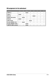
On Chip USB EHCI 1/2/3/4 shared ASM1042 USB3.0 controller - - PCIEx1_1 shared - - - - - - - PCI1 slot - - - - HD audio shared - - - - - - - On Chip USB EHCI 1/2/3 - shared - - - SATA controller - - - shared - - - - - - shared - - - - - - shared - - - - IRQ assignments for this motherboard A B C D E F G H PCIEx16_1 - - Realtek LAN controller - ASUS A55M-A Series 1-19 shared - - - - - shared - - - - -
On Chip USB EHCI 1/2/3/4 shared ASM1042 USB3.0 controller - - PCIEx1_1 shared - - - - - - - PCI1 slot - - - - HD audio shared - - - - - - - On Chip USB EHCI 1/2/3 - shared - - - SATA controller - - - shared - - - - - - shared - - - - - - shared - - - - IRQ assignments for this motherboard A B C D E F G H PCIEx16_1 - - Realtek LAN controller - ASUS A55M-A Series 1-19 shared - - - - - shared - - - - -
A55M-A User's Manual
Page 33
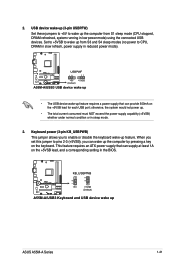
... This jumper allows you to pins 2-3 (+5VSB), you set this jumper to enable or disable the keyboard wake-up ASUS A55M-A Series 1-21 KB_USBPWB 12 23 A55M-A/USB3 +5V +5VSB (Default) A55M-A/USB3 Keyboard and USB device wake up feature. USB device wake-up (3-pin USBPFW) Set these jumpers to +5V to ... otherwise, the system would not power up the computer by pressing a key on the +5VSB lead for each USB port; 2. A55M-A/USB3 USBPWF 12 23 +5V +5VSB (Default) A55M-A/USB3 USB device wake up • The USB device wake-up feature requires a power supply that can wake up . • The...
... This jumper allows you to pins 2-3 (+5VSB), you set this jumper to enable or disable the keyboard wake-up ASUS A55M-A Series 1-21 KB_USBPWB 12 23 A55M-A/USB3 +5V +5VSB (Default) A55M-A/USB3 Keyboard and USB device wake up feature. USB device wake-up (3-pin USBPFW) Set these jumpers to +5V to ... otherwise, the system would not power up the computer by pressing a key on the +5VSB lead for each USB port; 2. A55M-A/USB3 USBPWF 12 23 +5V +5VSB (Default) A55M-A/USB3 USB device wake up • The USB device wake-up feature requires a power supply that can wake up . • The...

A55M-A User's Manual
Page 35
... ground pin of the connector. CPU FAN PWM CPU FAN IN CPU FAN PWR GND Rotation +12V GND ASUS A55M-A Series 1-23 DVI-D port. This port is for any DVI-D compatible device. CPU_FAN CHA_FAN A55M-A/USB3 A55M-A/USB3 CPU fan connector DO NOT forget to connect the fan cables to the fan connectors. USB 3.0 ports 11...
... ground pin of the connector. CPU FAN PWM CPU FAN IN CPU FAN PWR GND Rotation +12V GND ASUS A55M-A Series 1-23 DVI-D port. This port is for any DVI-D compatible device. CPU_FAN CHA_FAN A55M-A/USB3 A55M-A/USB3 CPU fan connector DO NOT forget to connect the fan cables to the fan connectors. USB 3.0 ports 11...

A55M-A User's Manual
Page 36
...supply are for an ATX power supply. 2. ATX12V EATXPWR +12V DC +12V DC A55M-A/USB3 GND GND +3 Volts +12 Volts +12 Volts +5V Standby Power OK PIN 1 GND +5 Volts GND +5 Volts GND +3 Volts +3 Volts PIN 1 A55M-A/USB3 ATX power connectors GND +5 Volts +5 Volts +5 Volts -5 Volts GND GND GND ...PSON# GND -12 Volts +3 Volts • We recommend that you intend to use a PSU with 20-pin and 4-pin power plugs, ensure that the 20-pin power plug can provide at http://support.asus. com...
...supply are for an ATX power supply. 2. ATX12V EATXPWR +12V DC +12V DC A55M-A/USB3 GND GND +3 Volts +12 Volts +12 Volts +5V Standby Power OK PIN 1 GND +5 Volts GND +5 Volts GND +3 Volts +3 Volts PIN 1 A55M-A/USB3 ATX power connectors GND +5 Volts +5 Volts +5 Volts -5 Volts GND GND GND ...PSON# GND -12 Volts +3 Volts • We recommend that you intend to use a PSU with 20-pin and 4-pin power plugs, ensure that the 20-pin power plug can provide at http://support.asus. com...
A55M-A User's Manual
Page 37
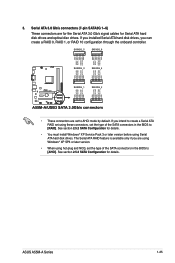
... GND RSATA_TXN4 RSATA_TXP4 GND GND RSATA_RXP3 RSATA_RXN3 GND RSATA_TXN3 RSATA_TXP3 GND A55M-A/USB3 SATA3G_1 SATA3G_2 GND RSATA_RXP1 RSATA_RXN1 GND RSATA_TXN1 RSATA_TXP1 GND GND RSATA_RXP2 RSATA_RXN2 GND RSATA_TXN2 RSATA_TXP2 GND A55M-A/USB3 SATA 3.0Gb/s connectors • These connectors are for the ... RAID 10 configuration through the onboard controller. See section 2.5.2 SATA Configuration for Serial ATA hard disk drives and optical disc drives. ASUS A55M-A Series 1-25 If you intend to create a Serial ATA RAID set using Serial ATA hard disk drives. 3. Serial ATA 3.0...
... GND RSATA_TXN4 RSATA_TXP4 GND GND RSATA_RXP3 RSATA_RXN3 GND RSATA_TXN3 RSATA_TXP3 GND A55M-A/USB3 SATA3G_1 SATA3G_2 GND RSATA_RXP1 RSATA_RXN1 GND RSATA_TXN1 RSATA_TXP1 GND GND RSATA_RXP2 RSATA_RXN2 GND RSATA_TXN2 RSATA_TXP2 GND A55M-A/USB3 SATA 3.0Gb/s connectors • These connectors are for the ... RAID 10 configuration through the onboard controller. See section 2.5.2 SATA Configuration for Serial ATA hard disk drives and optical disc drives. ASUS A55M-A Series 1-25 If you intend to create a Serial ATA RAID set using Serial ATA hard disk drives. 3. Serial ATA 3.0...
A55M-A User's Manual
Page 39
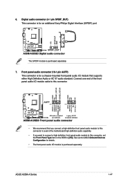
... connector (4-1 pin SPDIF_OUT) This connector is for an additional Sony/Philips Digital Interface (S/PDIF) port. +5V SPDIFOUT GND A55M-A/USB3 SPDIF_OUT A55M-A/USB3 Digital audio connector The S/PDIF module is purchased separately. See section 2.5.5 Onboard Devices Configuration for a chassis-mounted front panel... audio I /O module cable to this connector, set the Front Panel Type item in the BIOS to this connector. ASUS A55M-A ...
... connector (4-1 pin SPDIF_OUT) This connector is for an additional Sony/Philips Digital Interface (S/PDIF) port. +5V SPDIFOUT GND A55M-A/USB3 SPDIF_OUT A55M-A/USB3 Digital audio connector The S/PDIF module is purchased separately. See section 2.5.5 Onboard Devices Configuration for a chassis-mounted front panel... audio I /O module cable to this connector, set the Front Panel Type item in the BIOS to this connector. ASUS A55M-A ...
A55M-A User's Manual
Page 45
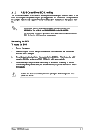
... To recover the BIOS: 1. The utility automatically checks the devices for A55M-A USB3). • The BIOS file in the support DVD may not be ...the optical drive or the USB flash drive that you press to load default BIOS values. 2.1.3 ASUS CrashFree BIOS 3 utility The ASUS CrashFree BIOS 3 is an auto recovery tool that contains the updated BIOS file. • Before... Setup to recover BIOS setting. Chapter 2: BIOS information 2-3 Download the latest BIOS file from the ASUS website at www.asus.com. DO NOT shut down or reset the system while updating the BIOS! Turn on the system...
... To recover the BIOS: 1. The utility automatically checks the devices for A55M-A USB3). • The BIOS file in the support DVD may not be ...the optical drive or the USB flash drive that you press to load default BIOS values. 2.1.3 ASUS CrashFree BIOS 3 utility The ASUS CrashFree BIOS 3 is an auto recovery tool that contains the updated BIOS file. • Before... Setup to recover BIOS setting. Chapter 2: BIOS information 2-3 Download the latest BIOS file from the ASUS website at www.asus.com. DO NOT shut down or reset the system while updating the BIOS! Turn on the system...
A55M-A User's Manual
Page 62
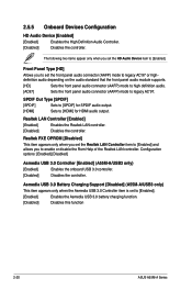
...] Sets to enable or disable the Rom Help of the Realtek LAN controller. Asmedia USB 3.0 Battery Charging Support [Disabled] (A55M-A/USB3 only) This item appears only when the Asmedia USB 3.0 Controller item is set the front panel audio connector (AAFP) mode ...panel audio connector (AAFP) mode to [Enabled]. [Enabled] Enables the Asmedia USB 3.0 battery charging function. [Disabled] Disables this function 2-20 ASUS A55M-A Series Realtek LAN Controller [Enabled] [Enabled] Enables the Realtek LAN controller. [Disabled] Disables the controller. Front Panel Type [HD] Allows you...
...] Sets to enable or disable the Rom Help of the Realtek LAN controller. Asmedia USB 3.0 Battery Charging Support [Disabled] (A55M-A/USB3 only) This item appears only when the Asmedia USB 3.0 Controller item is set the front panel audio connector (AAFP) mode ...panel audio connector (AAFP) mode to [Enabled]. [Enabled] Enables the Asmedia USB 3.0 battery charging function. [Disabled] Disables this function 2-20 ASUS A55M-A Series Realtek LAN Controller [Enabled] [Enabled] Enables the Realtek LAN controller. [Disabled] Disables the controller. Front Panel Type [HD] Allows you...
A55M-A User's Manual
Page 78
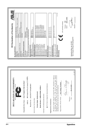
...: declare the following apparatus: ASUSTeK COMPUTER INC. 4F, No. 150, LI-TE Rd., PEITOU, TAIPEI 112, TAIWAN TAIWAN ASUS COMPUTER GmbH HARKORT STR. 21-23, 40880 RATINGEN GERMANY Product name : Motherboard Model name : A55M-A/USB3, A55M-A conform with the essential requirements of the following specifications: FCC Part 15, Subpart B, Unintentional Radiators Supplementary Information: This...
...: declare the following apparatus: ASUSTeK COMPUTER INC. 4F, No. 150, LI-TE Rd., PEITOU, TAIPEI 112, TAIWAN TAIWAN ASUS COMPUTER GmbH HARKORT STR. 21-23, 40880 RATINGEN GERMANY Product name : Motherboard Model name : A55M-A/USB3, A55M-A conform with the essential requirements of the following specifications: FCC Part 15, Subpart B, Unintentional Radiators Supplementary Information: This...

