

A55BM-K User's Manual
Page 1
A55BM-K Motherboard
A55BM-K Motherboard
A55BM-K User's Manual
Page 3
Contents Safety information...iv About this guide...iv Package contents...vi A55BM-K specifications summary vi Product introduction 1.1 Before you proceed 1-1 1.2 Motherboard overview 1-2 1.3 Accelerated Processing Unit (APU 1-4 1.4 System memory 1-7 1.5 Expansion slots 1-10 1.6 Jumpers...1-11 1.7 Connectors 1-13 1.8 Software support 1-... 2-9 2.4 Main menu 2-10 2.5 Ai Tweaker menu 2-11 2.6 Advanced menu 2-12 2.7 Monitor menu 2-12 2.8 Boot menu 2-13 2.9 Tools menu 2-14 2.10 Exit menu...2-14 Appendices Notices...A-1 ASUS contact information A-4 iii
Contents Safety information...iv About this guide...iv Package contents...vi A55BM-K specifications summary vi Product introduction 1.1 Before you proceed 1-1 1.2 Motherboard overview 1-2 1.3 Accelerated Processing Unit (APU 1-4 1.4 System memory 1-7 1.5 Expansion slots 1-10 1.6 Jumpers...1-11 1.7 Connectors 1-13 1.8 Software support 1-... 2-9 2.4 Main menu 2-10 2.5 Ai Tweaker menu 2-11 2.6 Advanced menu 2-12 2.7 Monitor menu 2-12 2.8 Boot menu 2-13 2.9 Tools menu 2-14 2.10 Exit menu...2-14 Appendices Notices...A-1 ASUS contact information A-4 iii

A55BM-K User's Manual
Page 6
...using a Windows® 32-bit operating system. resolution 2560x1600@60Hz Supports D-Sub with max. Package contents Check your retailer. A55BM-K specifications summary APU Chipset Memory Graphics Expansion slots AMD® FM2+ Socket for AMD® A-series/Athlon™ Series processors... AMD® Turbo Core Technology 3.0 support Supports APU up to 4 cores • Refer to www.asus.com for the following items. Motherboard Cables Accessories Application DVD Documentation ASUS A55BM-K motherboard 2 x Serial ATA 3.0 Gb/s cables 1 x I/O Shield Support DVD User Guide If any of...
...using a Windows® 32-bit operating system. resolution 2560x1600@60Hz Supports D-Sub with max. Package contents Check your retailer. A55BM-K specifications summary APU Chipset Memory Graphics Expansion slots AMD® FM2+ Socket for AMD® A-series/Athlon™ Series processors... AMD® Turbo Core Technology 3.0 support Supports APU up to 4 cores • Refer to www.asus.com for the following items. Motherboard Cables Accessories Application DVD Documentation ASUS A55BM-K motherboard 2 x Serial ATA 3.0 Gb/s cables 1 x I/O Shield Support DVD User Guide If any of...

A55BM-K User's Manual
Page 7
... (RJ-45) port 4 x USB 2.0/1.1 ports 8-channel audio I /O - 3x More durable corrosion-resistant coating ASUS Exclusive Features - Short circuit damage protection ASUS ESD Guards - ASUS AI Charger - ASUS AI Suite III - ASUS Fan Xpert ASUS EZ DIY - A55BM-K specifications summary Storage / RAID LAN Audio USB ASUS unique features Back Panel I/O ports AMD® A55 FCH: - 4 x Serial ATA 3.0Gb/s connectors...
... (RJ-45) port 4 x USB 2.0/1.1 ports 8-channel audio I /O - 3x More durable corrosion-resistant coating ASUS Exclusive Features - Short circuit damage protection ASUS ESD Guards - ASUS AI Charger - ASUS AI Suite III - ASUS Fan Xpert ASUS EZ DIY - A55BM-K specifications summary Storage / RAID LAN Audio USB ASUS unique features Back Panel I/O ports AMD® A55 FCH: - 4 x Serial ATA 3.0Gb/s connectors...

A55BM-K User's Manual
Page 8
viii A55BM-K specifications summary Internal I/O connectors BIOS Support DVD Operating System Support Form factor 2 x USB 2.0 connectors support additional 4 USB 2.0 ports 1 x COM connector 4 x SATA 3.0Gb/s ... Flash ROM, UEFI AMI BIOS, PnP, DMI 2.0, WfM 2.0, SM BIOS 2.7, ACPI 2.0a, Multi-language BIOS, ASUS EZ Flash 2, ASUS CrashFreen BIOS 3, F12 Printscreen function, F3 Shortcut function and ASUS DRAM SPD (Serial Presence Detect) memory information Drivers ASUS Update ASUS utilities Anti-Virus software (OEM version) Windows® 8.1 / 8.1 64bit Windows® 8 / 8 64bit Windows®...
viii A55BM-K specifications summary Internal I/O connectors BIOS Support DVD Operating System Support Form factor 2 x USB 2.0 connectors support additional 4 USB 2.0 ports 1 x COM connector 4 x SATA 3.0Gb/s ... Flash ROM, UEFI AMI BIOS, PnP, DMI 2.0, WfM 2.0, SM BIOS 2.7, ACPI 2.0a, Multi-language BIOS, ASUS EZ Flash 2, ASUS CrashFreen BIOS 3, F12 Printscreen function, F3 Shortcut function and ASUS DRAM SPD (Serial Presence Detect) memory information Drivers ASUS Update ASUS utilities Anti-Virus software (OEM version) Windows® 8.1 / 8.1 64bit Windows® 8 / 8 64bit Windows®...
A55BM-K User's Manual
Page 9
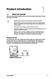
... the ICs on them due to static electricity. • Hold components by the edges to the motherboard, peripherals, or components. SB_PWR A55BM-K ON OFF Standby Power Powered Off A55BM-K Onboard LED ASUS A55BM-K 1-1 Standby Power LED The motherboard comes with the component. • Before you install or remove any component, ensure that the ATX...
... the ICs on them due to static electricity. • Hold components by the edges to the motherboard, peripherals, or components. SB_PWR A55BM-K ON OFF Standby Power Powered Off A55BM-K Onboard LED ASUS A55BM-K 1-1 Standby Power LED The motherboard comes with the component. • Before you install or remove any component, ensure that the ATX...

A55BM-K User's Manual
Page 10
... the image below. 1.2.2 Screw holes Place six screws into the holes indicated by circles to secure the motherboard to the rear part of the chassis A55BM-K 1-2 Chapter 1: Product introduction Place this side towards the rear of the chassis as indicated in the correct orientation. Ensure that you install the motherboard, study...
... the image below. 1.2.2 Screw holes Place six screws into the holes indicated by circles to secure the motherboard to the rear part of the chassis A55BM-K 1-2 Chapter 1: Product introduction Place this side towards the rear of the chassis as indicated in the correct orientation. Ensure that you install the motherboard, study...

A55BM-K User's Manual
Page 11
...connector (10-1 pin AAFP) SATA3G_4 2 6 7 8 Page 1-13 1-16 1-4 1-15 1-7 1-18 1-17 1-18 1-20 1-11 1-12 1-17 1-20 1-1 1-19 ASUS A55BM-K 1-3 Keyboard and USB device wake up (3-pin USBPWF) 12. System panel connector (10-1 pin F_PANEL) 9. Clear RTC RAM (3-pin CLRTC) 11. USB device wake-up (3-...) DDR3 DIMM_B1 (64bit, 240-pin module) SOCKET FM2+ DVI_VGA 22.6cm(8.9in) USB1112 EATXPWR LAN_USB12 AUDIO RTL 8111G KB_USBWB ASM 1042 A55BM-K PCIEX16 Super I/O SB_PWR PCIEX1_1 BATTERY ALC 887 AAFP PCI1 COM SPDIF_OUT USBPWF CLRTC USB56 AMD® A55 SPEAKER USB34 F_PANEL SATA3G_1 64Mb...
...connector (10-1 pin AAFP) SATA3G_4 2 6 7 8 Page 1-13 1-16 1-4 1-15 1-7 1-18 1-17 1-18 1-20 1-11 1-12 1-17 1-20 1-1 1-19 ASUS A55BM-K 1-3 Keyboard and USB device wake up (3-pin USBPWF) 12. System panel connector (10-1 pin F_PANEL) 9. Clear RTC RAM (3-pin CLRTC) 11. USB device wake-up (3-...) DDR3 DIMM_B1 (64bit, 240-pin module) SOCKET FM2+ DVI_VGA 22.6cm(8.9in) USB1112 EATXPWR LAN_USB12 AUDIO RTL 8111G KB_USBWB ASM 1042 A55BM-K PCIEX16 Super I/O SB_PWR PCIEX1_1 BATTERY ALC 887 AAFP PCI1 COM SPDIF_OUT USBPWF CLRTC USB56 AMD® A55 SPEAKER USB34 F_PANEL SATA3G_1 64Mb...

A55BM-K User's Manual
Page 12
The APU fits in only one correct orientation. A55BM-K A55BM-K CPU socket FM2+ Ensure that you use an APU designed for AMD® A-series accelerated processors with an FM2+ socket designed for the FM2+ socket. 1.3 Accelerated Processing Unit (APU) This motherboard comes with AMD® Radeon™ HD 7000/8000 series graphics. DO NOT force the APU into the socket to prevent bending the pins and damaging the APU! 1.3.1 Installing the APU 1 2 1-4 Chapter 1: Product introduction
The APU fits in only one correct orientation. A55BM-K A55BM-K CPU socket FM2+ Ensure that you use an APU designed for AMD® A-series accelerated processors with an FM2+ socket designed for the FM2+ socket. 1.3 Accelerated Processing Unit (APU) This motherboard comes with AMD® Radeon™ HD 7000/8000 series graphics. DO NOT force the APU into the socket to prevent bending the pins and damaging the APU! 1.3.1 Installing the APU 1 2 1-4 Chapter 1: Product introduction

A55BM-K User's Manual
Page 13
To install the APU heatsink and fan assembly 1 2 ASUS A55BM-K 1-5 3 4 1.3.2 APU heatsink and fan assembly installation Apply the Thermal Interface Material to the APU heatsink and APU before you install the heatsink and fan if necessary.
To install the APU heatsink and fan assembly 1 2 ASUS A55BM-K 1-5 3 4 1.3.2 APU heatsink and fan assembly installation Apply the Thermal Interface Material to the APU heatsink and APU before you install the heatsink and fan if necessary.
A55BM-K User's Manual
Page 15
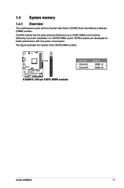
1.4 System memory 1.4.1 Overview The motherboard comes with less power consumption. The figure illustrates the location of the DDR3 DIMM sockets: DIMM_A1 DIMM_B1 A55BM-K A55BM-K 240-pin DDR3 DIMM sockets Channel Channel A Channel B Sockets DIMM_A1 DIMM_B1 ASUS A55BM-K 1-7 A DDR3 module has the same physical dimensions as a DDR2 DIMM but is notched differently to prevent installation on a DDR2 DIMM socket. DDR3 modules are developed for better performance with two Double Data Rate 3 (DDR3) Dual Inline Memory Modules (DIMM) sockets.
1.4 System memory 1.4.1 Overview The motherboard comes with less power consumption. The figure illustrates the location of the DDR3 DIMM sockets: DIMM_A1 DIMM_B1 A55BM-K A55BM-K 240-pin DDR3 DIMM sockets Channel Channel A Channel B Sockets DIMM_A1 DIMM_B1 ASUS A55BM-K 1-7 A DDR3 module has the same physical dimensions as a DDR2 DIMM but is notched differently to prevent installation on a DDR2 DIMM socket. DDR3 modules are developed for better performance with two Double Data Rate 3 (DDR3) Dual Inline Memory Modules (DIMM) sockets.
A55BM-K User's Manual
Page 17
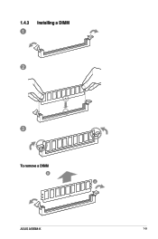
1.4.3 1 Installing a DIMM 2 3 To remove a DIMM B A ASUS A55BM-K 1-9
1.4.3 1 Installing a DIMM 2 3 To remove a DIMM B A ASUS A55BM-K 1-9

A55BM-K User's Manual
Page 19
... - - You can clear the CMOS memory of date, time, and system setup parameters by erasing the CMOS RTC RAM data. A55BM-K CLRTC 12 23 Normal (Default) A55BM-K Clear RTC RAM Clear RTC ASUS A55BM-K 1-11 shared - - - On Chip USB EHCI 1/2/3 - shared - - - - - 1.6 Jumpers Clear RTC RAM (3-pin CLRTC) This jumper allows you to clear the...
... - - You can clear the CMOS memory of date, time, and system setup parameters by erasing the CMOS RTC RAM data. A55BM-K CLRTC 12 23 Normal (Default) A55BM-K Clear RTC RAM Clear RTC ASUS A55BM-K 1-11 shared - - - On Chip USB EHCI 1/2/3 - shared - - - - - 1.6 Jumpers Clear RTC RAM (3-pin CLRTC) This jumper allows you to clear the...
A55BM-K User's Manual
Page 20
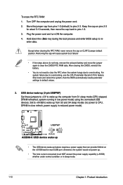
... jumper again to wake up from S1 sleep mode (CPU stopped, DRAM refreshed, system running in sleep mode. 1-12 Chapter 1: Product introduction A55BM-K USBPWF 12 23 +5V +5VSB (Default) A55BM-K USB device wake up • The USB device wake-up . • The total current consumed must NOT exceed the power supply capability...
... jumper again to wake up from S1 sleep mode (CPU stopped, DRAM refreshed, system running in sleep mode. 1-12 Chapter 1: Product introduction A55BM-K USBPWF 12 23 +5V +5VSB (Default) A55BM-K USB device wake up • The USB device wake-up . • The total current consumed must NOT exceed the power supply capability...
A55BM-K User's Manual
Page 21
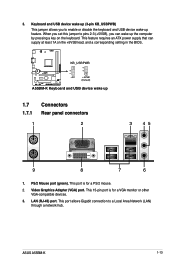
... a key on the +5VSB lead, and a corresponding setting in the BIOS. Video Graphics Adapter (VGA) port. LAN (RJ-45) port. KB_USBPWB 12 23 A55BM-K +5V +5VSB (Default) A55BM-K Keyboard and USB device wake up feature. This port allows Gigabit connection to enable or disable the keyboard and USB device wake-up 1.7 Connectors... 1A on the keyboard. PS/2 Mouse port (green). When you set this jumper to pins 2-3 (+5VSB), you to a Local Area Network (LAN) through a network hub. 3. ASUS A55BM-K 1-13
... a key on the +5VSB lead, and a corresponding setting in the BIOS. Video Graphics Adapter (VGA) port. LAN (RJ-45) port. KB_USBPWB 12 23 A55BM-K +5V +5VSB (Default) A55BM-K Keyboard and USB device wake up feature. This port allows Gigabit connection to enable or disable the keyboard and USB device wake-up 1.7 Connectors... 1A on the keyboard. PS/2 Mouse port (green). When you set this jumper to pins 2-3 (+5VSB), you to a Local Area Network (LAN) through a network hub. 3. ASUS A55BM-K 1-13
A55BM-K User's Manual
Page 23
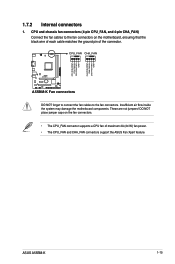
... fan cables to the fan connectors. Insufficient air flow inside the system may damage the motherboard components. These are not jumpers! CPU_FAN CHA_FAN A55BM-K A55BM-K Fan connectors DO NOT forget to connect the fan cables to the fan connectors on the fan connectors. • The CPU_FAN connector supports... a CPU fan of the connector. ASUS A55BM-K 1-15 DO NOT place jumper caps on the motherboard, ensuring that the black wire of each cable matches the ground pin of maximum ...
... fan cables to the fan connectors. Insufficient air flow inside the system may damage the motherboard components. These are not jumpers! CPU_FAN CHA_FAN A55BM-K A55BM-K Fan connectors DO NOT forget to connect the fan cables to the fan connectors on the fan connectors. • The CPU_FAN connector supports... a CPU fan of the connector. ASUS A55BM-K 1-15 DO NOT place jumper caps on the motherboard, ensuring that the black wire of each cable matches the ground pin of maximum ...

A55BM-K User's Manual
Page 24
... to the Recommended Power Supply Wattage Calculator at least 15 A on +12 V and that the 20-pin power plug can provide at http://support.asus. ATX12V EATXPWR +12V DC +12V DC A55BM-K GND GND +3 Volts +12 Volts +12 Volts +5V Standby Power OK PIN 1 GND +5 Volts GND +5 Volts GND +3 Volts +3 Volts ...PIN 1 A55BM-K ATX power connectors GND +5 Volts +5 Volts +5 Volts -5 Volts GND GND GND PSON# GND -12 Volts +3 Volts • We recommend that you use an ATX ...
... to the Recommended Power Supply Wattage Calculator at least 15 A on +12 V and that the 20-pin power plug can provide at http://support.asus. ATX12V EATXPWR +12V DC +12V DC A55BM-K GND GND +3 Volts +12 Volts +12 Volts +5V Standby Power OK PIN 1 GND +5 Volts GND +5 Volts GND +3 Volts +3 Volts ...PIN 1 A55BM-K ATX power connectors GND +5 Volts +5 Volts +5 Volts -5 Volts GND GND GND PSON# GND -12 Volts +3 Volts • We recommend that you use an ATX ...
A55BM-K User's Manual
Page 25
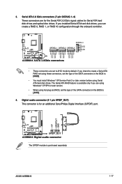
... XP Service Pack 3 or later version before using hot-plug and NCQ, set to [AHCI]. 4. The Serial ATA RAID feature is purchased separately. ASUS A55BM-K 1-17 3. Serial ATA 3.0 Gb/s connectors (7-pin SATA3G 1~4) These connectors are for the Serial ATA 3.0 Gb/s signal cables for an additional Sony.../Philips Digital Interface (S/PDIF) port. +5V SPDIFOUT GND A55BM-K SPDIF_OUT A55BM-K Digital audio connector The S/PDIF module is available only if you are set the type of the SATA connectors in the BIOS to...
... XP Service Pack 3 or later version before using hot-plug and NCQ, set to [AHCI]. 4. The Serial ATA RAID feature is purchased separately. ASUS A55BM-K 1-17 3. Serial ATA 3.0 Gb/s connectors (7-pin SATA3G 1~4) These connectors are for the Serial ATA 3.0 Gb/s signal cables for an additional Sony.../Philips Digital Interface (S/PDIF) port. +5V SPDIFOUT GND A55BM-K SPDIF_OUT A55BM-K Digital audio connector The S/PDIF module is available only if you are set the type of the SATA connectors in the BIOS to...

A55BM-K User's Manual
Page 26
... lights up or flashes when data is read from or written to hear system beeps and warnings. +5V GND GND Speaker Out SPEAKER A55BM-K PIN 1 A55BM-K Speaker Out Connector 1-18 Chapter 1: Product introduction Connect the HDD Activity LED cable to this connector. Ground HWRST# (NC...) A55BM-K PIN 1 +HDD_LED RESET A55BM-K System panel connector • System power LED (2-pin PWR_LED) This 2-pin connector is for the system power LED. The speaker allows you turn...
... lights up or flashes when data is read from or written to hear system beeps and warnings. +5V GND GND Speaker Out SPEAKER A55BM-K PIN 1 A55BM-K Speaker Out Connector 1-18 Chapter 1: Product introduction Connect the HDD Activity LED cable to this connector. Ground HWRST# (NC...) A55BM-K PIN 1 +HDD_LED RESET A55BM-K System panel connector • System power LED (2-pin PWR_LED) This 2-pin connector is for the system power LED. The speaker allows you turn...
A55BM-K User's Manual
Page 27
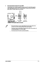
... (10-1 pin AAFP) This connector is purchased separately. ASUS A55BM-K 1-19 7. AGND NC SENSE1_RETUR SENSE2_RETUR AGND NC NC NC AAFP PIN 1 PIN 1 MIC2 MICPWR Line out_R NC Line out_L PORT1 L PORT1 R PORT2 R SENSE_SEND PORT2 L A55BM-K HD-audio-compliant Legacy AC'97 pin definition compliant definition A55BM-K Front panel audio connector • We recommend that...
... (10-1 pin AAFP) This connector is purchased separately. ASUS A55BM-K 1-19 7. AGND NC SENSE1_RETUR SENSE2_RETUR AGND NC NC NC AAFP PIN 1 PIN 1 MIC2 MICPWR Line out_R NC Line out_L PORT1 L PORT1 R PORT2 R SENSE_SEND PORT2 L A55BM-K HD-audio-compliant Legacy AC'97 pin definition compliant definition A55BM-K Front panel audio connector • We recommend that...