A55BM-A USB3 User's Manual
Page 6
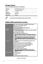
... 2.0 x1 slots 1 x PCI slot • PCIe 3.0 is damaged or missing, contact your retailer. Package contents Check your motherboard package for the following items. Motherboard Cables Accessories Application DVD Documentation ASUS A55BM-A/USB3 motherboard 2 x Serial ATA 3.0 Gb/s cables 1 x I/O Shield Support DVD User Guide If any of the above DIMMs... APU up to 4 cores • Refer to www.asus.com for the AMD® APU support list. resolution 2560x1600@60Hz Supports D-Sub with 16GB or above items is supported by FM2+ processors only. (continued on the next page) vi AMD...
... 2.0 x1 slots 1 x PCI slot • PCIe 3.0 is damaged or missing, contact your retailer. Package contents Check your motherboard package for the following items. Motherboard Cables Accessories Application DVD Documentation ASUS A55BM-A/USB3 motherboard 2 x Serial ATA 3.0 Gb/s cables 1 x I/O Shield Support DVD User Guide If any of the above DIMMs... APU up to 4 cores • Refer to www.asus.com for the AMD® APU support list. resolution 2560x1600@60Hz Supports D-Sub with 16GB or above items is supported by FM2+ processors only. (continued on the next page) vi AMD...
A55BM-A USB3 User's Manual
Page 11
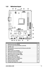
...FM2+ socket 4. DDR3 DIMM slots 6. Speaker connector (4-pin SPEAKER) 7. USB 2.0 connectors (10-1 pin USB34, USB56) 10. USB device wake-up (3-pin USBPWF) 12. Standby power LED (SB_PWR) 15. SATA 3.0Gb/s connectors (7-pin SATA3G_1~6) 8. Front panel audio connector (10-1 pin AAFP) ASUS A55BM-A/USB3 ...Page 1-12 1-16 1-4 1-15 1-7 1-18 1-17 1-18 1-20 1-11 1-12 1-19 1-20 1-1 1-19 1-3 Serial port connector (10-1 pin COM) 14. 1.2.3 Motherboard layout 1 2 3 4 5 18.3cm(7.2in) KBMS HDMI ATX12V...
...FM2+ socket 4. DDR3 DIMM slots 6. Speaker connector (4-pin SPEAKER) 7. USB 2.0 connectors (10-1 pin USB34, USB56) 10. USB device wake-up (3-pin USBPWF) 12. Standby power LED (SB_PWR) 15. SATA 3.0Gb/s connectors (7-pin SATA3G_1~6) 8. Front panel audio connector (10-1 pin AAFP) ASUS A55BM-A/USB3 ...Page 1-12 1-16 1-4 1-15 1-7 1-18 1-17 1-18 1-20 1-11 1-12 1-19 1-20 1-1 1-19 1-3 Serial port connector (10-1 pin COM) 14. 1.2.3 Motherboard layout 1 2 3 4 5 18.3cm(7.2in) KBMS HDMI ATX12V...
A55BM-A USB3 User's Manual
Page 12
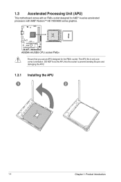
The APU fits in only one correct orientation. A55BM-A/USB3 A55BM-A/USB3 CPU socket FM2+ Ensure that you use an APU designed for AMD® A-series accelerated processors with AMD® Radeon™ HD 7000/8000 series graphics. DO NOT force the APU into the socket to prevent bending the pins and damaging the APU! 1.3.1 Installing the APU 1 2 1-4 Chapter 1: Product introduction 1.3 Accelerated Processing Unit (APU) This motherboard comes with an FM2+ socket designed for the FM2+ socket.
The APU fits in only one correct orientation. A55BM-A/USB3 A55BM-A/USB3 CPU socket FM2+ Ensure that you use an APU designed for AMD® A-series accelerated processors with AMD® Radeon™ HD 7000/8000 series graphics. DO NOT force the APU into the socket to prevent bending the pins and damaging the APU! 1.3.1 Installing the APU 1 2 1-4 Chapter 1: Product introduction 1.3 Accelerated Processing Unit (APU) This motherboard comes with an FM2+ socket designed for the FM2+ socket.


