A55BM-A USB3 User's Manual
Page 8
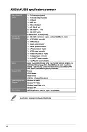
viii A55BM-A/USB3 specifications summary Back Panel I/O ports ...support additional 4 USB 2.0/1.1 ports 6 x SATA 3.0Gb/s connectors 1 x COM connector 1 x System panel connector 1 x Internal Speaker connector 1 x CPU fan connector (4-pin) 1 x S/PDIF output connector 1 x Chassis fan connector (4-pin) 1 x Front panel audio connector 1 x 24-pin EATX ...ACPI 2.0a, Multi-language BIOS, ASUS EZ Flash 2, ASUS CrashFreen BIOS 3, F12 Printscreen function, F3 Shortcut function and ASUS DRAM SPD (Serial Presence Detect) memory information Drivers ASUS Update ASUS utilities Anti-Virus software (OEM version...
viii A55BM-A/USB3 specifications summary Back Panel I/O ports ...support additional 4 USB 2.0/1.1 ports 6 x SATA 3.0Gb/s connectors 1 x COM connector 1 x System panel connector 1 x Internal Speaker connector 1 x CPU fan connector (4-pin) 1 x S/PDIF output connector 1 x Chassis fan connector (4-pin) 1 x Front panel audio connector 1 x 24-pin EATX ...ACPI 2.0a, Multi-language BIOS, ASUS EZ Flash 2, ASUS CrashFreen BIOS 3, F12 Printscreen function, F3 Shortcut function and ASUS DRAM SPD (Serial Presence Detect) memory information Drivers ASUS Update ASUS utilities Anti-Virus software (OEM version...
A55BM-A USB3 User's Manual
Page 11
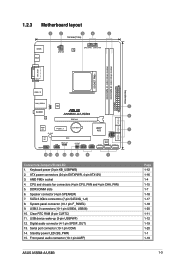
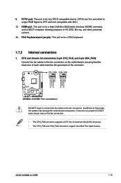
CPU and chassis fan connectors (4-pin CPU_FAN and 4-pin CHA_FAN) 5. USB 2.0 ...11. USB device wake-up (3-pin USBPWF) 12. SATA 3.0Gb/s connectors (7-pin SATA3G_1~6) 8. Front panel audio connector (10-1 pin AAFP) ASUS A55BM-A/USB3 Page 1-12 1-16 1-4 1-15 1-7 1-18 1-17 1-18 1-20 1-11 1-12 1-19 1-20 1-1 1-19 1-3 Standby power LED ...64bit, 240-pin module) DVI_VGA SOCKET FM2+ 22.6cm(8.9in) USB3_12 EATXPWR KB_USBWB LAN_USB12 ASM 1042 2 AUDIO A55BM-A/USB3 6 RTL 8111G PCIEX16 SATA3G_4 SATA3G_5 SATA3G_6 Super I/O SB_PWR PCIEX1_1 BATTERY AMD® A55 SPEAKER 7 ALC 887 ...
CPU and chassis fan connectors (4-pin CPU_FAN and 4-pin CHA_FAN) 5. USB 2.0 ...11. USB device wake-up (3-pin USBPWF) 12. SATA 3.0Gb/s connectors (7-pin SATA3G_1~6) 8. Front panel audio connector (10-1 pin AAFP) ASUS A55BM-A/USB3 Page 1-12 1-16 1-4 1-15 1-7 1-18 1-17 1-18 1-20 1-11 1-12 1-19 1-20 1-1 1-19 1-3 Standby power LED ...64bit, 240-pin module) DVI_VGA SOCKET FM2+ 22.6cm(8.9in) USB3_12 EATXPWR KB_USBWB LAN_USB12 ASM 1042 2 AUDIO A55BM-A/USB3 6 RTL 8111G PCIEX16 SATA3G_4 SATA3G_5 SATA3G_6 Super I/O SB_PWR PCIEX1_1 BATTERY AMD® A55 SPEAKER 7 ALC 887 ...
A55BM-A USB3 User's Manual
Page 12
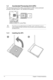
DO NOT force the APU into the socket to prevent bending the pins and damaging the APU! 1.3.1 Installing the APU 1 2 1-4 Chapter 1: Product introduction 1.3 Accelerated Processing Unit (APU) This motherboard comes with AMD® Radeon™ HD 7000/8000 series graphics. The APU fits in only one correct orientation. A55BM-A/USB3 A55BM-A/USB3 CPU socket FM2+ Ensure that you use an APU designed for AMD® A-series accelerated processors with an FM2+ socket designed for the FM2+ socket.
DO NOT force the APU into the socket to prevent bending the pins and damaging the APU! 1.3.1 Installing the APU 1 2 1-4 Chapter 1: Product introduction 1.3 Accelerated Processing Unit (APU) This motherboard comes with AMD® Radeon™ HD 7000/8000 series graphics. The APU fits in only one correct orientation. A55BM-A/USB3 A55BM-A/USB3 CPU socket FM2+ Ensure that you use an APU designed for AMD® A-series accelerated processors with an FM2+ socket designed for the FM2+ socket.

A55BM-A USB3 User's Manual
Page 20
...the CMOS, reinstall the battery. • You do not help, remove the onboard battery and move the cap back to default values. 2. A55BM-EA/USB3 USBPWF 12 23 +5V +5VSB (Default) A55BM-A/USB3 USB device wake up • The USB device wake-up from pins 1-2 (default) to re- To erase the RTC RAM: 1. ...Shut down the key during the boot process and enter BIOS setup to pins 2-3. Set to +5VSB to CPU, DRAM in slow refresh, power supply ...
...the CMOS, reinstall the battery. • You do not help, remove the onboard battery and move the cap back to default values. 2. A55BM-EA/USB3 USBPWF 12 23 +5V +5VSB (Default) A55BM-A/USB3 USB device wake up • The USB device wake-up from pins 1-2 (default) to re- To erase the RTC RAM: 1. ...Shut down the key during the boot process and enter BIOS setup to pins 2-3. Set to +5VSB to CPU, DRAM in slow refresh, power supply ...
A55BM-A USB3 User's Manual
Page 23
... maximum 2A (24 W) fan power. • The CPU_FAN and CHA_FAN connectors support the ASUS Fan Xpert feature. These are not jumpers! 9. CPU FAN PWM CPU FAN IN CPU FAN PWR GND CHA FAN PWM CHA FAN IN CHA FAN PWR GND ASUS A55BM-A/USB3 1-15 DVI-D port. DVI-D can't be converted to output RGB Signal to the...
... maximum 2A (24 W) fan power. • The CPU_FAN and CHA_FAN connectors support the ASUS Fan Xpert feature. These are not jumpers! 9. CPU FAN PWM CPU FAN IN CPU FAN PWR GND CHA FAN PWM CHA FAN IN CHA FAN PWR GND ASUS A55BM-A/USB3 1-15 DVI-D port. DVI-D can't be converted to output RGB Signal to the...

A55BM-A USB3 User's Manual
Page 37
... optimized default Selects the boot device priority Displays the system properties of the BIOS setup program Displays the CPU/motherboard temperature, CPU/5V/3.3V/12V voltage output, CPU/chassis fan speed Exits the BIOS setup program without saving the changes, saves the changes and resets the system, or enters the Advanced Mode CPU Volt. ASUS A55BM-A/USB3 2-7
... optimized default Selects the boot device priority Displays the system properties of the BIOS setup program Displays the CPU/motherboard temperature, CPU/5V/3.3V/12V voltage output, CPU/chassis fan speed Exits the BIOS setup program without saving the changes, saves the changes and resets the system, or enters the Advanced Mode CPU Volt. ASUS A55BM-A/USB3 2-7
A55BM-A USB3 User's Manual
Page 41
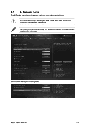
Scroll down to malfunction. The configuration options for this section vary depending on the CPU and DIMM model you to configure overclocking-related items. Be cautious when changing the settings of the Ai Tweaker menu items. Incorrect field values can cause the system to display the following items: ASUS A55BM-A/USB3 2-11 2.5 Ai Tweaker menu The Ai Tweaker menu items allow you installed on the motherboard.
Scroll down to malfunction. The configuration options for this section vary depending on the CPU and DIMM model you to configure overclocking-related items. Be cautious when changing the settings of the Ai Tweaker menu items. Incorrect field values can cause the system to display the following items: ASUS A55BM-A/USB3 2-11 2.5 Ai Tweaker menu The Ai Tweaker menu items allow you installed on the motherboard.

A55BM-A USB3 User's Manual
Page 42
Be cautious when changing the settings of the Advanced menu items. Incorrect field values can cause the system to malfunction. 2.7 Monitor menu The Monitor menu displays the system temperature/power status, and allows you to change the settings for the CPU and other system devices. 2.6 Advanced menu The Advanced menu items allow you to change the fan settings. 2-12 Chapter 2: Getting started
Be cautious when changing the settings of the Advanced menu items. Incorrect field values can cause the system to malfunction. 2.7 Monitor menu The Monitor menu displays the system temperature/power status, and allows you to change the settings for the CPU and other system devices. 2.6 Advanced menu The Advanced menu items allow you to change the fan settings. 2-12 Chapter 2: Getting started


