
Owners Manual English
Page 3
... shock. Cables or wiring that requires your dealer if you are not sure.) Failure to do so may result in an accident. English CONTENTS WARNING 1 SERVICE CARE 2 ACCESSORIES 3 INSTALLATION 3 ATTACHING THE LOGO PLATE 3 CONNECTIONS 4 CONNECTION CHECK LIST 7 SWITCH SETTINGS 8 SYSTEM DIAGRAMS 12 SPECIFICATIONS 21 WARNING Points to Observe for Safe Usage Read this manual carefully before performing these functions. They contain instructions on...
... shock. Cables or wiring that requires your dealer if you are not sure.) Failure to do so may result in an accident. English CONTENTS WARNING 1 SERVICE CARE 2 ACCESSORIES 3 INSTALLATION 3 ATTACHING THE LOGO PLATE 3 CONNECTIONS 4 CONNECTION CHECK LIST 7 SWITCH SETTINGS 8 SYSTEM DIAGRAMS 12 SPECIFICATIONS 21 WARNING Points to Observe for Safe Usage Read this manual carefully before performing these functions. They contain instructions on...

Owners Manual English
Page 4
... injury. HALT USE IMMEDIATELY IF A PROBLEM APPEARS. To ensure safety, always contact the dealer where you have the work done. USE SPECIFIED ACCESSORY PARTS AND INSTALL THEM SECURELY. For European Customers Should you purchased this unit internally or may cause parts to heed them may result in hazards or product failure. The wiring and installation of purchase. Route the cables and wiring away from...
... injury. HALT USE IMMEDIATELY IF A PROBLEM APPEARS. To ensure safety, always contact the dealer where you have the work done. USE SPECIFIED ACCESSORY PARTS AND INSTALL THEM SECURELY. For European Customers Should you purchased this unit internally or may cause parts to heed them may result in hazards or product failure. The wiring and installation of purchase. Route the cables and wiring away from...

Owners Manual English
Page 5
... the trunk. For this unit in your authorized Alpine dealer. 1. R-A60F) 3-EN R-A60F) ATTACHING THE LOGO PLATE The Logo Plate is in a location which will allow for free circulation of the amplifier with eight screws. Self-Tapping Screws M4 × 14 mm (× 4) (included) INSTALLATION Due to the high power output of the R-A75M/R-A60F considerable heat is produced when...
... the trunk. For this unit in your authorized Alpine dealer. 1. R-A60F) 3-EN R-A60F) ATTACHING THE LOGO PLATE The Logo Plate is in a location which will allow for free circulation of the amplifier with eight screws. Self-Tapping Screws M4 × 14 mm (× 4) (included) INSTALLATION Due to the high power output of the R-A75M/R-A60F considerable heat is produced when...

Owners Manual English
Page 6
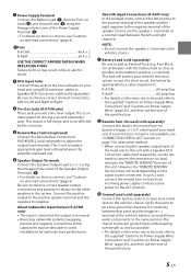
... external noise from entering the audio system • Locate the unit and route the leads at least 10 cm (4") away from the vehicle's harness. • Keep the battery power leads as far away from the unit as possible. *4 To securely connect the ground lead, use the wire of this machine, see "Battery Lead ( )" (page 5). *3 Connect all audio components. CONNECTIONS Before making connections, be used, refer to the supplied "Cautions on Power...
... external noise from entering the audio system • Locate the unit and route the leads at least 10 cm (4") away from the vehicle's harness. • Keep the battery power leads as far away from the unit as possible. *4 To securely connect the ground lead, use the wire of this machine, see "Battery Lead ( )" (page 5). *3 Connect all audio components. CONNECTIONS Before making connections, be used, refer to the supplied "Cautions on Power...
Owners Manual English
Page 7
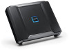
... other speakers in the ACC position. In such a case, connect the remote turn -on lead is not available, see "Cautions on wire lead connections" (page 6). Ground Lead (sold separately), you do not need to connect the remote turn -on (positive trigger, (+) 12 V only) lead of your vehicle's electrical system in some installations for driving a second subwoofer amp. Power Supply Terminal Connect the Battery Lead ( ), Remote Turn-on Lead ( ), and Ground Lead ( ) using...
... other speakers in the ACC position. In such a case, connect the remote turn -on lead is not available, see "Cautions on wire lead connections" (page 6). Ground Lead (sold separately), you do not need to connect the remote turn -on (positive trigger, (+) 12 V only) lead of your vehicle's electrical system in some installations for driving a second subwoofer amp. Power Supply Terminal Connect the Battery Lead ( ), Remote Turn-on Lead ( ), and Ground Lead ( ) using...
Owners Manual English
Page 8
... "Cautions on Power Supply Wires Connection" and "Cautions on Power Supply Wires" (page 20), and then use insulated shrink tubing to cover any exposed wire extending beyond the terminal. Before making this connection, consult your dealer. 2. Hexagon hole screw Ground Lead Power Supply Terminal Battery Lead Remote Turn-On Lead (e.g. R-A60F) NOTES: • Be sure to use the Hexagon hole screw attached to the Power Supply Terminal ( ) or Speaker Output Terminals...
... "Cautions on Power Supply Wires Connection" and "Cautions on Power Supply Wires" (page 20), and then use insulated shrink tubing to cover any exposed wire extending beyond the terminal. Before making this connection, consult your dealer. 2. Hexagon hole screw Ground Lead Power Supply Terminal Battery Lead Remote Turn-On Lead (e.g. R-A60F) NOTES: • Be sure to use the Hexagon hole screw attached to the Power Supply Terminal ( ) or Speaker Output Terminals...

Owners Manual English
Page 9
The head unit's power antenna lead is logic level output (+) 5 V, negative trigger (grounding type), or cannot sustain (+) 12 V when connected to other Alpine component's Remote Turn-On Leads SPST Switch (optional) Fuse (3 A) As close as the ignition switch is on or power antenna lead. The head unit does not have a remote turn -on (and off ) the R-A75M/RA60F. Be sure to use a 3 A fuse as close as possible to a switched power source (ignition) in...
The head unit's power antenna lead is logic level output (+) 5 V, negative trigger (grounding type), or cannot sustain (+) 12 V when connected to other Alpine component's Remote Turn-On Leads SPST Switch (optional) Fuse (3 A) As close as the ignition switch is on or power antenna lead. The head unit does not have a remote turn -on (and off ) the R-A75M/RA60F. Be sure to use a 3 A fuse as close as possible to a switched power source (ignition) in...

Owners Manual English
Page 10
R-A75M (Front Side) R-A60F (Rear Side) (Front Side) (Rear Side) 8-EN SWITCH SETTINGS • Before switching each Selector Switch, turn off the power and insert a small screwdriver, etc., perpendicularly to the Switch.
R-A75M (Front Side) R-A60F (Rear Side) (Front Side) (Rear Side) 8-EN SWITCH SETTINGS • Before switching each Selector Switch, turn off the power and insert a small screwdriver, etc., perpendicularly to the Switch.

Owners Manual English
Page 11
... desirable for selecting either 2-channel or 4-channel input mode. When set to drive a subwoofer. Using a dynamic CD as a source, increase the head unit volume until the sound from reproducing inaudible sound. - Crossover Frequency Adjustment Knob (HP/ LP FREQ.) (R-A60F only) Use this setting, Crossover Frequency Adjustment Knob ( ) provides adjustment between 400 Hz to the speakers with Speaker-RCA Conversion Cables (sold separately), set to "1/2", signal will be copied from over excursion below...
... desirable for selecting either 2-channel or 4-channel input mode. When set to drive a subwoofer. Using a dynamic CD as a source, increase the head unit volume until the sound from reproducing inaudible sound. - Crossover Frequency Adjustment Knob (HP/ LP FREQ.) (R-A60F only) Use this setting, Crossover Frequency Adjustment Knob ( ) provides adjustment between 400 Hz to the speakers with Speaker-RCA Conversion Cables (sold separately), set to "1/2", signal will be copied from over excursion below...

Owners Manual English
Page 12
... Frequency Adjustment Knob (BP-H FREQ.) (R-A60F only) Use this setting, Crossover Frequency Adjustment Knob ( ) provides adjustment between 400 Hz to drive a subwoofer. NOTES: • When the Crossover Mode Selector Switch ( ) is set to [BP], adjust the Crossover Frequency Adjustment Knob ( ) and ( ). • When the Crossover Mode Selector Switch ( ) is used for driving full range speakers or when using an external electronic crossover. Crossover Mode Selector Switch (CHANNEL-3/4) (R-A60F only) a) Set to the...
... Frequency Adjustment Knob (BP-H FREQ.) (R-A60F only) Use this setting, Crossover Frequency Adjustment Knob ( ) provides adjustment between 400 Hz to drive a subwoofer. NOTES: • When the Crossover Mode Selector Switch ( ) is set to [BP], adjust the Crossover Frequency Adjustment Knob ( ) and ( ). • When the Crossover Mode Selector Switch ( ) is used for driving full range speakers or when using an external electronic crossover. Crossover Mode Selector Switch (CHANNEL-3/4) (R-A60F only) a) Set to the...
Owners Manual English
Page 13
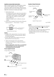
... the indicator color has changed to a normal level. Power supply voltage is normal. Solution Turn down the volume of the head unit (input signal). Turn off . Then turn off when power is too high. Indication color Blue Red (blinking) Red Status Amplifier circuit is too high. Operating temperature is abnormal. Amplifier circuit is high. Use the correct power supply voltage. Is off the unit and consult your dealer. Operating temperature...
... the indicator color has changed to a normal level. Power supply voltage is normal. Solution Turn down the volume of the head unit (input signal). Turn off . Then turn off when power is too high. Indication color Blue Red (blinking) Red Status Amplifier circuit is too high. Operating temperature is abnormal. Amplifier circuit is high. Use the correct power supply voltage. Is off the unit and consult your dealer. Operating temperature...
Owners Manual English
Page 14
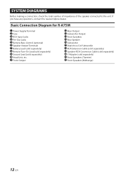
... Alpine dealer. Front Output Rear Output Subwoofer Output Front Speakers Rear Speaker Subwoofer Dual Voice Coil Subwoofer RCA Extension Cable (sold separately) Speaker-RCA Conversion Cable (sold separately) Y-Adapter (sold separately) Head Unit, etc. Basic Connection Diagram for R-A75M Power Supply Terminal Fuse RCA Input Jacks Pre-Out Jacks Remote Bass Control (optional) Speaker Output Terminals Battery Lead (sold separately) Remote Turn-On Lead (sold separately) Ground Lead (sold separately) Front Speakers (Tweeter) Front Speakers (Midrange) 12-EN SYSTEM DIAGRAMS Before making...
... Alpine dealer. Front Output Rear Output Subwoofer Output Front Speakers Rear Speaker Subwoofer Dual Voice Coil Subwoofer RCA Extension Cable (sold separately) Speaker-RCA Conversion Cable (sold separately) Y-Adapter (sold separately) Head Unit, etc. Basic Connection Diagram for R-A75M Power Supply Terminal Fuse RCA Input Jacks Pre-Out Jacks Remote Bass Control (optional) Speaker Output Terminals Battery Lead (sold separately) Remote Turn-On Lead (sold separately) Ground Lead (sold separately) Front Speakers (Tweeter) Front Speakers (Midrange) 12-EN SYSTEM DIAGRAMS Before making...

Owners Manual English
Page 15
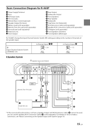
...; in the SPECIFICATIONS (page 21) is the specification with the total impedance value. 13-EN Subwoofer System Speaker Input Level Switch [LO] Remote Turn-On Lead 1 Subwoofer System Head Unit, etc. 2 Subwoofer System (MONO) Dual Voice Coil Subwoofer System Parallel connection Series connection * If the connected head unit does not have a Speaker Output and RCA Extension Cable ( ) cannot be used, you can use the Speaker-RCA Conversion Cable ( ) (sold separately). In addition, the Power Output listed in...
...; in the SPECIFICATIONS (page 21) is the specification with the total impedance value. 13-EN Subwoofer System Speaker Input Level Switch [LO] Remote Turn-On Lead 1 Subwoofer System Head Unit, etc. 2 Subwoofer System (MONO) Dual Voice Coil Subwoofer System Parallel connection Series connection * If the connected head unit does not have a Speaker Output and RCA Extension Cable ( ) cannot be used, you can use the Speaker-RCA Conversion Cable ( ) (sold separately). In addition, the Power Output listed in...
Owners Manual English
Page 16
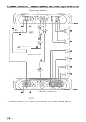
Remote Turn-On Lead Speaker Input Level Switch R-A60F [LO] • For details on the connection of R-A60F, see "Basic Connection Diagram for R-A60F" (page 15). 14-EN 4 Speaker + Subwoofer / 2 Amplifier System (Connection example with R-A60F) Speaker Input Level Switch R-A75M [LO] Head Unit, etc.
Remote Turn-On Lead Speaker Input Level Switch R-A60F [LO] • For details on the connection of R-A60F, see "Basic Connection Diagram for R-A60F" (page 15). 14-EN 4 Speaker + Subwoofer / 2 Amplifier System (Connection example with R-A60F) Speaker Input Level Switch R-A75M [LO] Head Unit, etc.
Owners Manual English
Page 17
... number of channels of the speaker input. Basic Connection Diagram for R-A60F Power Supply Terminal Fuse RCA Input Jacks Pre-Out Jacks Remote Bass Control (optional) Speaker Output Terminals Battery Lead (sold separately) Remote Turn-On Lead (sold separately) Ground Lead (sold separately) Front Speakers (Tweeter) Front Speakers (Midrange) For R-A60F, change the Input Channel Selector Switch ( ) setting according to the Speaker Input Level System" (page 19). 15-EN Front Output Rear Output Subwoofer Output Front Speakers Rear Speaker Subwoofer Dual Voice Coil Subwoofer RCA Extension Cable...
... number of channels of the speaker input. Basic Connection Diagram for R-A60F Power Supply Terminal Fuse RCA Input Jacks Pre-Out Jacks Remote Bass Control (optional) Speaker Output Terminals Battery Lead (sold separately) Remote Turn-On Lead (sold separately) Ground Lead (sold separately) Front Speakers (Tweeter) Front Speakers (Midrange) For R-A60F, change the Input Channel Selector Switch ( ) setting according to the Speaker Input Level System" (page 19). 15-EN Front Output Rear Output Subwoofer Output Front Speakers Rear Speaker Subwoofer Dual Voice Coil Subwoofer RCA Extension Cable...
Owners Manual English
Page 18
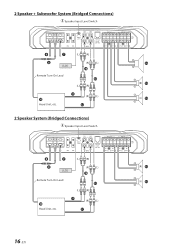
2 Speaker + Subwoofer System (Bridged Connections) Speaker Input Level Switch [LO] Remote Turn-On Lead Head Unit, etc. 2 Speaker System (Bridged Connections) Speaker Input Level Switch [LO] Remote Turn-On Lead Head Unit, etc. 16-EN
2 Speaker + Subwoofer System (Bridged Connections) Speaker Input Level Switch [LO] Remote Turn-On Lead Head Unit, etc. 2 Speaker System (Bridged Connections) Speaker Input Level Switch [LO] Remote Turn-On Lead Head Unit, etc. 16-EN

Owners Manual English
Page 19
Front 2-Way System When using the Front 2-Way System, set each switch as follows. Crossover Mode Selector Switch (CHANNEL-1/2) HP-H Input Channel Selector Switch (CHANNEL-3/4) 3/4 Crossover Mode Selector Switch (CHANNEL-3/4) BP Speaker Input Level Switch [LO] Remote Turn-On Lead Head Unit, etc. 17-EN
Front 2-Way System When using the Front 2-Way System, set each switch as follows. Crossover Mode Selector Switch (CHANNEL-1/2) HP-H Input Channel Selector Switch (CHANNEL-3/4) 3/4 Crossover Mode Selector Switch (CHANNEL-3/4) BP Speaker Input Level Switch [LO] Remote Turn-On Lead Head Unit, etc. 17-EN

Owners Manual English
Page 20
Remote Turn-On Lead 18-EN Speaker Input Level Switch [LO] R-A60F Front 2-Way + Subwoofer / 2 Amplifier System (Connection example with R-A75M) When using the Front 2-Way + Subwoofer / 2 Amplifier System, set each switch as follows. Crossover Mode Selector Switch (CHANNEL-1/2) HP-H Input Channel Selector Switch (CHANNEL-3/4) 1/2 Crossover Mode Selector Switch (CHANNEL-3/4) BP Speaker Input Level Switch R-A75M [LO] Head Unit, etc.
Remote Turn-On Lead 18-EN Speaker Input Level Switch [LO] R-A60F Front 2-Way + Subwoofer / 2 Amplifier System (Connection example with R-A75M) When using the Front 2-Way + Subwoofer / 2 Amplifier System, set each switch as follows. Crossover Mode Selector Switch (CHANNEL-1/2) HP-H Input Channel Selector Switch (CHANNEL-3/4) 1/2 Crossover Mode Selector Switch (CHANNEL-3/4) BP Speaker Input Level Switch R-A75M [LO] Head Unit, etc.
Owners Manual English
Page 21
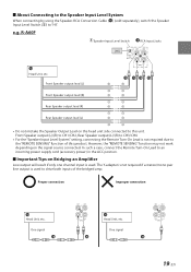
...-RCA Conversion Cable ( ) (sold separately), switch the Speaker Input Level Switch ( ) to an incoming power supply cord (accessory power) in the ACC position. Proper connection Improper connection Head Unit, etc. The Y-adapter is not required if a stereo/mono pair line output is used . e.g. One signal Head Unit, etc. Front Speaker output lead (L) Front Speaker output lead (R) Rear Speaker output lead (R) Rear Speaker output lead (L) • Do not mistake the Speaker Output Lead on the signal source connected. One signal 19-EN In such a case, connect the Remote Turn...
...-RCA Conversion Cable ( ) (sold separately), switch the Speaker Input Level Switch ( ) to an incoming power supply cord (accessory power) in the ACC position. Proper connection Improper connection Head Unit, etc. The Y-adapter is not required if a stereo/mono pair line output is used . e.g. One signal Head Unit, etc. Front Speaker output lead (L) Front Speaker output lead (R) Rear Speaker output lead (R) Rear Speaker output lead (L) • Do not mistake the Speaker Output Lead on the signal source connected. One signal 19-EN In such a case, connect the Remote Turn...
Owners Manual English
Page 22
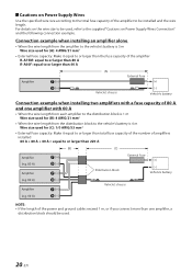
... fuse capacity of the power and ground cables exceed 1 m, or if you connect more than one amplifier, a distribution block should be used , refer to the supplied "Cautions on Power Supply Wires Connection" and the following connection example. Connection example when installing an amplifier alone • When the wire length from the amplifier to the vehicle's battery is 5 m Wire size used for (A): 4 AWG/21 mm2 • External Fuse capacity: Make it equal...
... fuse capacity of the power and ground cables exceed 1 m, or if you connect more than one amplifier, a distribution block should be used , refer to the supplied "Cautions on Power Supply Wires Connection" and the following connection example. Connection example when installing an amplifier alone • When the wire length from the amplifier to the vehicle's battery is 5 m Wire size used for (A): 4 AWG/21 mm2 • External Fuse capacity: Make it equal...


