Owners Manual
Page 3
... Fast Forward/Backward 19 Repeat Play 19 Controlling DVD Changer 19 Navigation System Operation (Optional) Turning on the Navigation Mode 20 Interrupt Feature (NAV. ENGLISH Contents Operating Instructions WARNING ...WARNING 3 CAUTION 3 PRECAUTIONS 4 Basic Operation Detaching the Front Panel 6 Attaching the Front Panel 6 Initial System Start-Up 6 Turning Power On and Off 7 Raising the Monitor 7 Lowering the Monitor 7 Selecting the Monitor's Opening Position ........ 7 Adjusting the Monitor...
... Fast Forward/Backward 19 Repeat Play 19 Controlling DVD Changer 19 Navigation System Operation (Optional) Turning on the Navigation Mode 20 Interrupt Feature (NAV. ENGLISH Contents Operating Instructions WARNING ...WARNING 3 CAUTION 3 PRECAUTIONS 4 Basic Operation Detaching the Front Panel 6 Attaching the Front Panel 6 Initial System Start-Up 6 Turning Power On and Off 7 Raising the Monitor 7 Lowering the Monitor 7 Selecting the Monitor's Opening Position ........ 7 Adjusting the Monitor...
Owners Manual
Page 22
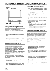
... amplifier. Interrupt Feature(NAV.MIX OUT) With an ALPINE navigation system connected to select ON or OFF. MIX. 1 When the monitor is open , press and hold MUTE/SETUP for at least 2 seconds. Navigation System Operation (Optional) SOURCE/ PWR MUTE/SETUP 3 Press g or f to the CVA-1004, the navigation system's voice guidance is mixed in and output from...
... amplifier. Interrupt Feature(NAV.MIX OUT) With an ALPINE navigation system connected to select ON or OFF. MIX. 1 When the monitor is open , press and hold MUTE/SETUP for at least 2 seconds. Navigation System Operation (Optional) SOURCE/ PWR MUTE/SETUP 3 Press g or f to the CVA-1004, the navigation system's voice guidance is mixed in and output from...
Owners Manual
Page 32
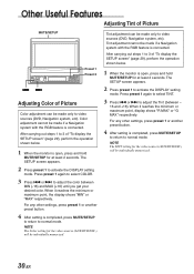
...Color of "To display the SETUP screen" (page 29), perform the operation shown below . 1 When the monitor is completed, press MUTE/SETUP to return to video sources (DVD, Navigation system, etc). When it reaches the minimum or maximum point, display shows "R MAX" or "G MAX" respectively.... For any other settings, press preset 1 or another preset button. 4 After setting is connected. Tint adjustment can be made if a Navigation system with the RGB feature is connected. The SETUP screen appears. 2 Press preset 1 to activate the DISPLAY setting mode. The SETUP screen...
...Color of "To display the SETUP screen" (page 29), perform the operation shown below . 1 When the monitor is completed, press MUTE/SETUP to return to video sources (DVD, Navigation system, etc). When it reaches the minimum or maximum point, display shows "R MAX" or "G MAX" respectively.... For any other settings, press preset 1 or another preset button. 4 After setting is connected. Tint adjustment can be made if a Navigation system with the RGB feature is connected. The SETUP screen appears. 2 Press preset 1 to activate the DISPLAY setting mode. The SETUP screen...
Owners Manual
Page 38
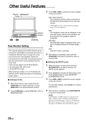
...display on page 39. There are two ways to ON in "Setting the External Input" on page 37), and a rear-seat monitor and navigation system are output. 36-EN SEL 1 When the monitor is turned ON (as shown in "Displaying Spectrum Analyzer"(page 38). OFF : AUX OUT mode is canceled. 4 After setting ... 1 to 4 on this page so the DVD picture and sound are connected to the CVA-1004, the picture/sound for at least 2 seconds, or press REAR ON on the optional Remote Control. . 2 Press CHG/R.SEL to select MONITOR-1 OUT or MONITOR-2 OUT. 3 Press g or f to select the mode to display on the rear-...
...display on page 39. There are two ways to ON in "Setting the External Input" on page 37), and a rear-seat monitor and navigation system are output. 36-EN SEL 1 When the monitor is turned ON (as shown in "Displaying Spectrum Analyzer"(page 38). OFF : AUX OUT mode is canceled. 4 After setting ... 1 to 4 on this page so the DVD picture and sound are connected to the CVA-1004, the picture/sound for at least 2 seconds, or press REAR ON on the optional Remote Control. . 2 Press CHG/R.SEL to select MONITOR-1 OUT or MONITOR-2 OUT. 3 Press g or f to select the mode to display on the rear-...
Owners Manual
Page 43
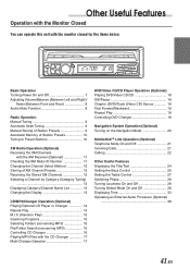
...Monitor Closed You can operate this unit with the CD Changer 17 Multi-Changer Selection 17 DVD/Video CD/CD Player Operation (Optional) Playing DVD/Video CD/CD 18 Still/Pause 18 Chapter (DVD)/Track (Video CD) Sensor 18 Fast Forward/Backward 19 Repeat Play 19 Controlling DVD Changer 19 Navigation... System Operation (Optional) Turning on the Navigation Mode 20 MobileHubTM Link Operation (Optional) Telephone Mode On and Off 21 Incoming Calls 21 Calling 22 Other ...
...Monitor Closed You can operate this unit with the CD Changer 17 Multi-Changer Selection 17 DVD/Video CD/CD Player Operation (Optional) Playing DVD/Video CD/CD 18 Still/Pause 18 Chapter (DVD)/Track (Video CD) Sensor 18 Fast Forward/Backward 19 Repeat Play 19 Controlling DVD Changer 19 Navigation... System Operation (Optional) Turning on the Navigation Mode 20 MobileHubTM Link Operation (Optional) Telephone Mode On and Off 21 Incoming Calls 21 Calling 22 Other ...
Owners Manual
Page 44
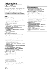
...Make sure the antenna is properly connected; replace with a new one. Check your authorized Alpine dealer. This guide will not operate with the vehicle's ignition off . - Press the Reset switch with the navigation system are not securely made . - Allow the vehicle's interior temperature to the DVD/CD...8226; Connections with a ballpoint pen or other pointed article. • Weak or no battery power. - Check the connections with the navigation system and connect the cables correctly and firmly. Check the fuse on the battery lead of consumption. Make sure the antenna is too...
...Make sure the antenna is properly connected; replace with a new one. Check your authorized Alpine dealer. This guide will not operate with the vehicle's ignition off . - Press the Reset switch with the navigation system are not securely made . - Allow the vehicle's interior temperature to the DVD/CD...8226; Connections with a ballpoint pen or other pointed article. • Weak or no battery power. - Check the connections with the navigation system and connect the cables correctly and firmly. Check the fuse on the battery lead of consumption. Make sure the antenna is too...
Owners Manual
Page 52
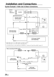
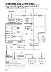
.../DIV 50-EN For details on how to set to ON: Output is from Subwoofer. Speakers 2 1 Rear or Subwoofers∗ Amplifier (NVE-N852A/NVE-N871A) Navigation System (Sold Separately) 3 " 5 4 6 NORM EQ/DIV DVD Video Player (Sold Separately) ! (Yellow) REMOTE IN (White/Brown) 9 (Yellow) 7 (White) (Red) 8 REMOTE OUT (White/Brown) CD Changer...
.../DIV 50-EN For details on how to set to ON: Output is from Subwoofer. Speakers 2 1 Rear or Subwoofers∗ Amplifier (NVE-N852A/NVE-N871A) Navigation System (Sold Separately) 3 " 5 4 6 NORM EQ/DIV DVD Video Player (Sold Separately) ! (Yellow) REMOTE IN (White/Brown) 9 (Yellow) 7 (White) (Red) 8 REMOTE OUT (White/Brown) CD Changer...
Owners Manual
Page 53
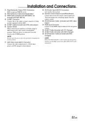
... in the EQ/DIV position. RCA Extension Cable (Included with DVD video player) " RGB Input Connector Connect to the RGB output terminal of the navigation system. # Ai-NET Cable (Included with CD Changer) $ Ai-NET Cable (Included with DVD Changer) % RCA Extension Cable (Included with DVD...System Switch When connecting an equalizer or divider using AiNET feature, place this terminal. 8 AUX Audio Input (AUX1) Connectors (not used for the Navigation System, use the RGB conversion cable KWE-503N (sold separately). 51-EN This lead outputs the controlling signals from the remote control. ! NOTE...
... in the EQ/DIV position. RCA Extension Cable (Included with DVD video player) " RGB Input Connector Connect to the RGB output terminal of the navigation system. # Ai-NET Cable (Included with CD Changer) $ Ai-NET Cable (Included with DVD Changer) % RCA Extension Cable (Included with DVD...System Switch When connecting an equalizer or divider using AiNET feature, place this terminal. 8 AUX Audio Input (AUX1) Connectors (not used for the Navigation System, use the RGB conversion cable KWE-503N (sold separately). 51-EN This lead outputs the controlling signals from the remote control. ! NOTE...
Owners Manual
Page 54
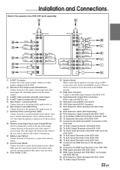
... & (White) (Yellow) ( $# ∗3 NORM EQ/DIV ^ KCE-150V (Sold Separately) TV Tuner (Sold Separately) COLOR ON ∗2 CONTROL OFF Navigation System ~ (Sold Separately) (NVE-N852A/NVE-871A) Rear Camera (Sold Separately) For details of each setting of external devices, refer to "Setting the External... Expansion Box" (page 35), "Rear Monitor Setting" (page 36), "Setting the External Input" (page 37) and "Setting Front/Rear/ Subwoofer Preout of the External Expansion Box" (page...
... & (White) (Yellow) ( $# ∗3 NORM EQ/DIV ^ KCE-150V (Sold Separately) TV Tuner (Sold Separately) COLOR ON ∗2 CONTROL OFF Navigation System ~ (Sold Separately) (NVE-N852A/NVE-871A) Rear Camera (Sold Separately) For details of each setting of external devices, refer to "Setting the External... Expansion Box" (page 35), "Rear Monitor Setting" (page 36), "Setting the External Input" (page 37) and "Setting Front/Rear/ Subwoofer Preout of the External Expansion Box" (page...
Owners Manual
Page 55
...) + RCA Extension Cable (Included with KCE-150V) ^ To Video Output Terminals 53-EN Connect to the RGB Terminal of the Navigation System @ Connect to the RGB Input Terminal of the CVA-1004 [ RGB Cable (Included with KCE-104V) \ RGB Cable (Included with NVE-N852, not included with NVE-N871A) ] RCA...(7.5A) # System Switch When connecting an equalizer or divider using the sheet metal screw provided. Connect to the AUX Input (AUX1) Connectors of the CVA-1004 / To AUX1 Output Terminals of the KCE-104V : To AUX2 Output Terminals of the KCE-104V . To Sound Input Terminals of the KCE-104V...
...) + RCA Extension Cable (Included with KCE-150V) ^ To Video Output Terminals 53-EN Connect to the RGB Terminal of the Navigation System @ Connect to the RGB Input Terminal of the CVA-1004 [ RGB Cable (Included with KCE-104V) \ RGB Cable (Included with NVE-N852, not included with NVE-N871A) ] RCA...(7.5A) # System Switch When connecting an equalizer or divider using the sheet metal screw provided. Connect to the AUX Input (AUX1) Connectors of the CVA-1004 / To AUX1 Output Terminals of the KCE-104V : To AUX2 Output Terminals of the KCE-104V . To Sound Input Terminals of the KCE-104V...


