User Guide
Page 8
... found to comply with EMC Directive 73/23/EEC as amended by 92/31/EEC and 93/68/EEC, in a commercial environment. Japanese Compliance (Voluntary Control Council Initiative) This is operated in accordance with: ■ EN55022 (1998) Emissions ■ EN55024 (1998) Immunity: - vii This equipment has been tested and found to...
... found to comply with EMC Directive 73/23/EEC as amended by 92/31/EEC and 93/68/EEC, in a commercial environment. Japanese Compliance (Voluntary Control Council Initiative) This is operated in accordance with: ■ EN55022 (1998) Emissions ■ EN55024 (1998) Immunity: - vii This equipment has been tested and found to...
User Guide
Page 12
... 8-5 SCSI Midplane 8-5 I/O Modules 8-6 I/O Module Configurations 8-7 Cable Lengths Supported 8-7 SATA Storage Enclosure Technical Specifications 8-7 Currently Supported Disk Drives 8-7 Serial ATA Interface 8-8 SATA I/O Modules 8-8 SATA Cables 8-8 SATA Configurations 8-8 FC Storage Enclosure Technical Specifications 8-9 Disk Drives 8-9 Daisy Chaining Adaptec FC Enclosures 8-9 A Configuring the RAID Controller (FS4500 only) Communication Parameters A-2 Navigating the Terminal Emulation Software A-2 Initial Screen A-2 Creating a Logical...
... 8-5 SCSI Midplane 8-5 I/O Modules 8-6 I/O Module Configurations 8-7 Cable Lengths Supported 8-7 SATA Storage Enclosure Technical Specifications 8-7 Currently Supported Disk Drives 8-7 Serial ATA Interface 8-8 SATA I/O Modules 8-8 SATA Cables 8-8 SATA Configurations 8-8 FC Storage Enclosure Technical Specifications 8-9 Disk Drives 8-9 Daisy Chaining Adaptec FC Enclosures 8-9 A Configuring the RAID Controller (FS4500 only) Communication Parameters A-2 Navigating the Terminal Emulation Software A-2 Initial Screen A-2 Creating a Logical...
User Guide
Page 39
... at one time. Damage to flow into the enclosure and cool the disk drives and enclosure. For drive carrier installation instructions, see page 2-9. Important Safety Precautions Before you remove a drive carrier, read these important cautionary notes: ! During installation, ensure that helps control installation and removal, and have a mechanical button-activated cam system that the...
... at one time. Damage to flow into the enclosure and cool the disk drives and enclosure. For drive carrier installation instructions, see page 2-9. Important Safety Precautions Before you remove a drive carrier, read these important cautionary notes: ! During installation, ensure that helps control installation and removal, and have a mechanical button-activated cam system that the...
User Guide
Page 51
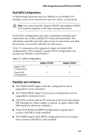
... JBOD configurations require drive carriers with MUX cards installed. ■ The FS4050 single SATA JBOD configuration does not require drive carriers with MUX cards installed. 5-4 Note: You cannot include Adaptec FS4100 and Adaptec FS4500 I /O processor configuration can include one FS4100 or one , two, three, or four hosts. Dual SATA configurations provide a redundant controller and make better...
... JBOD configurations require drive carriers with MUX cards installed. ■ The FS4050 single SATA JBOD configuration does not require drive carriers with MUX cards installed. 5-4 Note: You cannot include Adaptec FS4100 and Adaptec FS4500 I /O processor configuration can include one FS4100 or one , two, three, or four hosts. Dual SATA configurations provide a redundant controller and make better...
User Guide
Page 54
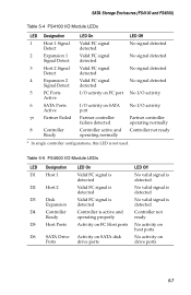
Table 5-5 FS4500 I /O activity 7a Partner Failed Partner controller failure detected Partner controller operating normally 8 Controller Ready Controller active and Controller not ready operating normally a In single controller configurations, this LED is active and operating properly Controller not ready D5 Host Ports Activity on FC Host ports No activity on host ports D6 SATA Drive Activity on SATA disk Ports drive ports...
Table 5-5 FS4500 I /O activity 7a Partner Failed Partner controller failure detected Partner controller operating normally 8 Controller Ready Controller active and Controller not ready operating normally a In single controller configurations, this LED is active and operating properly Controller not ready D5 Host Ports Activity on FC Host ports No activity on host ports D6 SATA Drive Activity on SATA disk Ports drive ports...
User Guide
Page 55
... by battery back-up is not used. See Drive Carrier LEDs on your Adaptec Storage Enclosure CD to the Adaptec Storage Enclosure CD for detailed information about LED functions. 5-8 SATA Storage Enclosures (FS4100 and FS4500) Table 5-5 FS4500 I/O Module LEDs LED Designation D7a Partner Failed LED On Partner controller has failed D8-1 Cache/BBU Fault ■ Data...
... by battery back-up is not used. See Drive Carrier LEDs on your Adaptec Storage Enclosure CD to the Adaptec Storage Enclosure CD for detailed information about LED functions. 5-8 SATA Storage Enclosures (FS4100 and FS4500) Table 5-5 FS4500 I/O Module LEDs LED Designation D7a Partner Failed LED On Partner controller has failed D8-1 Cache/BBU Fault ■ Data...
User Guide
Page 58
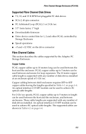
.... ■ FC Arbitrated Loop (FCAL) 1 or 2 Gb/sec ■ 3.5" form factor, 1" high ■ Downloadable firmware ■ Drive device control bits for loop expansion. Copper cabling between the host and the enclosure. For 2 Gb/sec speeds, FCAL copper cables up to achieve FC optical... disk drives installed at an enclosure speed of disk drives installed. FCAL copper cables up to 5 meters can be used between enclosures. An optical interface I /O SFP module can be used between the host and the enclosure, and between enclosures for 1, 2 and other FCAL controlled by the Adaptec FC ...
.... ■ FC Arbitrated Loop (FCAL) 1 or 2 Gb/sec ■ 3.5" form factor, 1" high ■ Downloadable firmware ■ Drive device control bits for loop expansion. Copper cabling between the host and the enclosure. For 2 Gb/sec speeds, FCAL copper cables up to achieve FC optical... disk drives installed at an enclosure speed of disk drives installed. FCAL copper cables up to 5 meters can be used between enclosures. An optical interface I /O SFP module can be used between the host and the enclosure, and between enclosures for 1, 2 and other FCAL controlled by the Adaptec FC ...
User Guide
Page 71
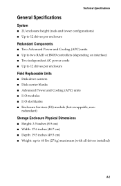
... cm) ■ Width: 17.6 inches (44.7 cm) ■ Depth: 19.5 inches (49.5 cm) ■ Weight: up to 12 drives per enclosure Field Replaceable Units ■ Disk drive carriers ■ Disk carrier blanks ■ Advanced Power and Cooling (APC) units ■ I/O modules ■ I/O slot blanks ■ Enclosure ...9632; 2U enclosure height (rack and tower configurations) ■ Up to 12 drives per enclosure Redundant Components ■ Two Advanced Power and Cooling (APC) units ■ Up to two RAID or JBOD controllers (depending on interface) ■ Two independent AC power cords ■ Up...
... cm) ■ Width: 17.6 inches (44.7 cm) ■ Depth: 19.5 inches (49.5 cm) ■ Weight: up to 12 drives per enclosure Field Replaceable Units ■ Disk drive carriers ■ Disk carrier blanks ■ Advanced Power and Cooling (APC) units ■ I/O modules ■ I/O slot blanks ■ Enclosure ...9632; 2U enclosure height (rack and tower configurations) ■ Up to 12 drives per enclosure Redundant Components ■ Two Advanced Power and Cooling (APC) units ■ Up to two RAID or JBOD controllers (depending on interface) ■ Two independent AC power cords ■ Up...
User Guide
Page 75
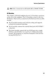
I/O Modules The Adaptec U320 SCSI midplane has two I /O modules connect to the two SCSI buses. The I /O module connectors on the rear of the midplane. There is a dual-bus ... IDs 0 to 5 and 8 to 5. 8-6 Without the Joiner module, the backplane is also a connector for the Enclosure Services (ES) module. ■ The ES module monitors and controls cooling and supports in-band environmental reporting. ■ The IO module contains the external (dual port) SCSI VHDCI connectors. ■ The Joiner module connects the...
I/O Modules The Adaptec U320 SCSI midplane has two I /O modules connect to the two SCSI buses. The I /O module connectors on the rear of the midplane. There is a dual-bus ... IDs 0 to 5 and 8 to 5. 8-6 Without the Joiner module, the backplane is also a connector for the Enclosure Services (ES) module. ■ The ES module monitors and controls cooling and supports in-band environmental reporting. ■ The IO module contains the external (dual port) SCSI VHDCI connectors. ■ The Joiner module connects the...
User Guide
Page 77
... specification, version 1. The interconnect has controlled impedance (50 ohm single-ended, 100 ohm differential) supporting the 1.5 Gb/ sec data rate and allows expansion to additional enclosures. Both I /O modules available--the FS4100 and the FS4500. The minimum length is purely dependent on the host HBA connector selection. The Adaptec FS4500 supports RAID levels 0, 1, 0/1, 3, 5, 10, 30...
... specification, version 1. The interconnect has controlled impedance (50 ohm single-ended, 100 ohm differential) supporting the 1.5 Gb/ sec data rate and allows expansion to additional enclosures. Both I /O modules available--the FS4100 and the FS4500. The minimum length is purely dependent on the host HBA connector selection. The Adaptec FS4500 supports RAID levels 0, 1, 0/1, 3, 5, 10, 30...
User Guide
Page 78
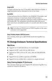
... to from more hosts and added security of a second controller for mix of disk drive vendors in a system for a total of 120 drives. 8-9 The redundant controller provides data access from one to ten Adaptec FC enclosures together in a single enclosure. Note: Including an FS4100 and an FS4500 together in a system. Dual SATA A dual enclosure has two...
... to from more hosts and added security of a second controller for mix of disk drive vendors in a system for a total of 120 drives. 8-9 The redundant controller provides data access from one to ten Adaptec FC enclosures together in a single enclosure. Note: Including an FS4100 and an FS4500 together in a system. Dual SATA A dual enclosure has two...
User Guide
Page 79
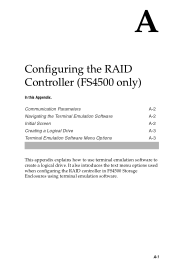
It also introduces the text menu options used when configuring the RAID controller in FS4500 Storage Enclosures using terminal emulation software. Communication Parameters A-2 Navigating the Terminal Emulation Software A-2 Initial Screen A-2 Creating a Logical Drive A-3 Terminal Emulation Software Menu Options A-3 This appendix explains how to use terminal emulation software to create a logical drive. A-1 A Configuring the RAID Controller (FS4500 only) In this Appendix.
It also introduces the text menu options used when configuring the RAID controller in FS4500 Storage Enclosures using terminal emulation software. Communication Parameters A-2 Navigating the Terminal Emulation Software A-2 Initial Screen A-2 Creating a Logical Drive A-3 Terminal Emulation Software Menu Options A-3 This appendix explains how to use terminal emulation software to create a logical drive. A-1 A Configuring the RAID Controller (FS4500 only) In this Appendix.
User Guide
Page 80
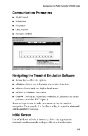
...display the data transfer rates. A-2 Initial Screen Use to open the view and edit Logical drives menu. For example, L is the shortcut key to refresh, if necessary. Configuring the RAID Controller (FS4500 only) Communication Parameters ■ 38,400 baud ■ 8 data bits ■ No ...parity ■ One stop bit ■ No flow control Navigating the Terminal Emulation Software ■ Arrow keys-Move to options. &#...
...display the data transfer rates. A-2 Initial Screen Use to open the view and edit Logical drives menu. For example, L is the shortcut key to refresh, if necessary. Configuring the RAID Controller (FS4500 only) Communication Parameters ■ 38,400 baud ■ 8 data bits ■ No ...parity ■ One stop bit ■ No flow control Navigating the Terminal Emulation Software ■ Arrow keys-Move to options. &#...
User Guide
Page 81
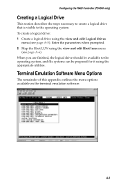
...you are finished, the logical drive should be available to the operating system. Enter the parameters when prompted. 2 Map the Host LUN using the view and edit Host luns menu (see page A-5). Configuring the RAID Controller (FS4500 only) Creating a Logical Drive This section describes the steps necessary... to create a logical drive that is visible to the operating system, and file systems can be prepared for it using ...
...you are finished, the logical drive should be available to the operating system. Enter the parameters when prompted. 2 Map the Host LUN using the view and edit Host luns menu (see page A-5). Configuring the RAID Controller (FS4500 only) Creating a Logical Drive This section describes the steps necessary... to create a logical drive that is visible to the operating system, and file systems can be prepared for it using ...
User Guide
Page 82
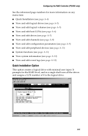
... page A-5) ■ View and edit logical volumes (see page A-5) ■ View and edit host LUNs (see page A-6) ■ View and edit drives (see page A-7) ■ View and edit channels (see page A-8) ■ View and edit configuration parameters (see page A-9) ■ View and edit ...; View system information (see page A-12) ■ View and edit event logs (see page A-12) Quick Installation Option This option creates a logical drive with minimal user input. A-4 Configuring the RAID Controller (FS4500 only) See the referenced page numbers for the RAID level, and in a single shelf uses all the...
... page A-5) ■ View and edit logical volumes (see page A-5) ■ View and edit host LUNs (see page A-6) ■ View and edit drives (see page A-7) ■ View and edit channels (see page A-8) ■ View and edit configuration parameters (see page A-9) ■ View and edit ...; View system information (see page A-12) ■ View and edit event logs (see page A-12) Quick Installation Option This option creates a logical drive with minimal user input. A-4 Configuring the RAID Controller (FS4500 only) See the referenced page numbers for the RAID level, and in a single shelf uses all the...
User Guide
Page 83
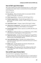
... a valid volume is selected. Configuring the RAID Controller (FS4500 only) View and Edit Logical Drives Option This option displays the Volume Information list, if a valid volume is selected. A-5 View and Edit Logical Volumes Option A logical volume is available, the drive can be added to increase the overall capacity of... volumes, which will appear as Write-Back, Write Through or Default for instance, from Primary to the alternate (for the selected logical drive. If no valid volume is selected, it prompts you to create one . If no valid volume is selected then the menu prompts...
... a valid volume is selected. Configuring the RAID Controller (FS4500 only) View and Edit Logical Drives Option This option displays the Volume Information list, if a valid volume is selected. A-5 View and Edit Logical Volumes Option A logical volume is available, the drive can be added to increase the overall capacity of... volumes, which will appear as Write-Back, Write Through or Default for instance, from Primary to the alternate (for the selected logical drive. If no valid volume is selected, it prompts you to create one . If no valid volume is selected then the menu prompts...
User Guide
Page 84
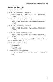
...Controller (FS4500 only) View and Edit Host LUNs Submenu options: ■ CHL 0 ID xxx (Primary Controller) LUN# LV/LD (Type) DRV# Partition# Size (MB) RAID (Level) ■ CHL 0 ID xxx (Secondary Controller) LUN# LV/LD (Type) DRV# Partition# Size (MB) RAID (Level) ■ CHL 1 ID xxx (Primary Controller)...) ■ CHL 1 ID xxx (Secondary Controller) LUN# LV/LD (Type) DRV# Partition# Size (MB) RAID (Level) If no logical drives or volumes are assigned, the submenu changes from an information line to: ■ CHL Y ID xxx (Z Controller) Logical Drive Logical Volume ■ Edit Host-ID/WWN Name...
...Controller (FS4500 only) View and Edit Host LUNs Submenu options: ■ CHL 0 ID xxx (Primary Controller) LUN# LV/LD (Type) DRV# Partition# Size (MB) RAID (Level) ■ CHL 0 ID xxx (Secondary Controller) LUN# LV/LD (Type) DRV# Partition# Size (MB) RAID (Level) ■ CHL 1 ID xxx (Primary Controller)...) ■ CHL 1 ID xxx (Secondary Controller) LUN# LV/LD (Type) DRV# Partition# Size (MB) RAID (Level) If no logical drives or volumes are assigned, the submenu changes from an information line to: ■ CHL Y ID xxx (Z Controller) Logical Drive Logical Volume ■ Edit Host-ID/WWN Name...
User Guide
Page 85
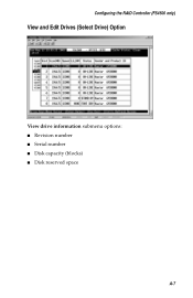
Configuring the RAID Controller (FS4500 only) View and Edit Drives (Select Drive) Option View drive information submenu options: ■ Revision number ■ Serial number ■ Disk capacity (blocks) ■ Disk reserved space A-7
Configuring the RAID Controller (FS4500 only) View and Edit Drives (Select Drive) Option View drive information submenu options: ■ Revision number ■ Serial number ■ Disk capacity (blocks) ■ Disk reserved space A-7
User Guide
Page 86
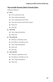
Configuring the RAID Controller (FS4500 only) View and Edit Channels (Select Channel) Option Submenu Options: ■ Host ■ View and edit scsi Id ■ View chip information ■ View channel ... rate ■ Issue lip ■ RCCOM ■ View chip information ■ Data rate ■ Drive/Serial ■ Primary controller scsi id ■ Secondary controller scsi id ■ View chip information ■ Data rate ■ Issue lip ■ Drive/SATA ■ Primary controller scsi id ■ Secondary controller scsi id ■ View chip information ■ Data rate A-8
Configuring the RAID Controller (FS4500 only) View and Edit Channels (Select Channel) Option Submenu Options: ■ Host ■ View and edit scsi Id ■ View chip information ■ View channel ... rate ■ Issue lip ■ RCCOM ■ View chip information ■ Data rate ■ Drive/Serial ■ Primary controller scsi id ■ Secondary controller scsi id ■ View chip information ■ Data rate ■ Issue lip ■ Drive/SATA ■ Primary controller scsi id ■ Secondary controller scsi id ■ View chip information ■ Data rate A-8
User Guide
Page 87
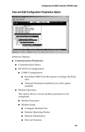
Configuring the RAID Controller (FS4500 only) View and Edit Configuration Parameters Option Submenu Options: ■ Communication Parameters ■ Communication Status ■ RS-232 Port Configuration ■ COM1 Configuration ■ Baud ...
Configuring the RAID Controller (FS4500 only) View and Edit Configuration Parameters Option Submenu Options: ■ Communication Parameters ■ Communication Status ■ RS-232 Port Configuration ■ COM1 Configuration ■ Baud ...