User Guide
Page 5
...CONSEQUENTIAL DAMAGES, INCLUDING WITHOUT LIMITATION LOSS OF DATA, ARISING FROM BREACH OF ANY EXPRESS OR IMPLIED WARRANTY ARE NOT THE RESPONSIBILITY OF ADAPTEC AND, TO THE EXTENT PERMITTED BY LAW, ARE HEREBY EXCLUDED BOTH FOR PROPERTY DAMAGE, AND TO THE EXTENT NOT UNCONSCIONABLE, FOR... HEREAFTER MIGHT OTHERWISE ARISE RESPECT TO THIS PRODUCT. Adaptec, Inc. ("Adaptec") warrants to Adaptec and providing proof of unauthorized service or parts. 3. If the product should become the property of this warranty. 4. This warranty gives you specific legal rights, and you may also have other ...
...CONSEQUENTIAL DAMAGES, INCLUDING WITHOUT LIMITATION LOSS OF DATA, ARISING FROM BREACH OF ANY EXPRESS OR IMPLIED WARRANTY ARE NOT THE RESPONSIBILITY OF ADAPTEC AND, TO THE EXTENT PERMITTED BY LAW, ARE HEREBY EXCLUDED BOTH FOR PROPERTY DAMAGE, AND TO THE EXTENT NOT UNCONSCIONABLE, FOR... HEREAFTER MIGHT OTHERWISE ARISE RESPECT TO THIS PRODUCT. Adaptec, Inc. ("Adaptec") warrants to Adaptec and providing proof of unauthorized service or parts. 3. If the product should become the property of this warranty. 4. This warranty gives you specific legal rights, and you may also have other ...
User Guide
Page 7
... LOST PROFITS, LOST SAVINGS, OR LOSS OF DATA, EVEN IF ADAPTEC OR A LICENSOR HAS BEEN ADVISED OF THE POSSIBILITY OF SUCH DAMAGES, OR FOR ANY CLAIM BY ANY OTHER PARTY. All rights in the Software not specifically granted in materials or workmanship, you may not apply to you ...have any different terms will not export or re-export the Software or documentation in any jurisdiction, then such provision shall be enforceable against Adaptec unless Adaptec gives its distributor is unable ...
... LOST PROFITS, LOST SAVINGS, OR LOSS OF DATA, EVEN IF ADAPTEC OR A LICENSOR HAS BEEN ADVISED OF THE POSSIBILITY OF SUCH DAMAGES, OR FOR ANY CLAIM BY ANY OTHER PARTY. All rights in the Software not specifically granted in materials or workmanship, you may not apply to you ...have any different terms will not export or re-export the Software or documentation in any jurisdiction, then such provision shall be enforceable against Adaptec unless Adaptec gives its distributor is unable ...
User Guide
Page 11
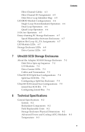
... SCSI Storage Enclosures About the Adaptec SC4100 Storage Enclosure 7-2 Disk Drive Spin-up Sequence 7-2 I/O Modules 7-2 Drive Carrier LEDs 7-3 Cables and Termination 7-3 Ultra320 SCSI Split-bus Configurations 7-4 Split-bus SCSI IDs 7-4 Configuring a Split-bus Enclosure 7-5 Ultra320 SCSI Joined-bus Configurations 7-5 Joined-bus SCSI IDs 7-5 Configuring Joined-Bus 7-6 8 Technical Specifications General Specifications 8-2 System 8-2 Redundant Components 8-2 Field Replaceable...
... SCSI Storage Enclosures About the Adaptec SC4100 Storage Enclosure 7-2 Disk Drive Spin-up Sequence 7-2 I/O Modules 7-2 Drive Carrier LEDs 7-3 Cables and Termination 7-3 Ultra320 SCSI Split-bus Configurations 7-4 Split-bus SCSI IDs 7-4 Configuring a Split-bus Enclosure 7-5 Ultra320 SCSI Joined-bus Configurations 7-5 Joined-bus SCSI IDs 7-5 Configuring Joined-Bus 7-6 8 Technical Specifications General Specifications 8-2 System 8-2 Redundant Components 8-2 Field Replaceable...
User Guide
Page 12
... Bus 8-5 SCSI Midplane 8-5 I/O Modules 8-6 I/O Module Configurations 8-7 Cable Lengths Supported 8-7 SATA Storage Enclosure Technical Specifications 8-7 Currently Supported Disk Drives 8-7 Serial ATA Interface 8-8 SATA I/O Modules 8-8 SATA Cables 8-8 SATA Configurations 8-8 FC Storage Enclosure Technical Specifications 8-9 Disk Drives 8-9 Daisy Chaining Adaptec FC Enclosures 8-9 A Configuring the RAID Controller (FS4500 only) Communication Parameters A-2 Navigating the Terminal Emulation Software A-2 Initial Screen A-2 Creating a Logical...
... Bus 8-5 SCSI Midplane 8-5 I/O Modules 8-6 I/O Module Configurations 8-7 Cable Lengths Supported 8-7 SATA Storage Enclosure Technical Specifications 8-7 Currently Supported Disk Drives 8-7 Serial ATA Interface 8-8 SATA I/O Modules 8-8 SATA Cables 8-8 SATA Configurations 8-8 FC Storage Enclosure Technical Specifications 8-9 Disk Drives 8-9 Daisy Chaining Adaptec FC Enclosures 8-9 A Configuring the RAID Controller (FS4500 only) Communication Parameters A-2 Navigating the Terminal Emulation Software A-2 Initial Screen A-2 Creating a Logical...
User Guide
Page 15
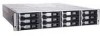
...enclosure ■ Adaptec SC4100 Ultra320 SCSI JBOD enclosure ■ Adaptec FC4100 Fibre Channel JBOD enclosure The Guide assumes that you have basic knowledge of Fibre Channel (FC), Serial ATA (SATA), Small Computer System Interface (SCSI), and Redundant Array of Independent Disks... ■ Adaptec FS4500 Fibre Channel-to set up and use Adaptec's 2U Storage Enclosures. This Guide does not provide any information on your Adaptec Storage Enclosure. the FS4500 enclosure is managed by Adaptec Storage Examiner; It also assumes that present model-specific information and requirements...
...enclosure ■ Adaptec SC4100 Ultra320 SCSI JBOD enclosure ■ Adaptec FC4100 Fibre Channel JBOD enclosure The Guide assumes that you have basic knowledge of Fibre Channel (FC), Serial ATA (SATA), Small Computer System Interface (SCSI), and Redundant Array of Independent Disks... ■ Adaptec FS4500 Fibre Channel-to set up and use Adaptec's 2U Storage Enclosures. This Guide does not provide any information on your Adaptec Storage Enclosure. the FS4500 enclosure is managed by Adaptec Storage Examiner; It also assumes that present model-specific information and requirements...
User Guide
Page 18
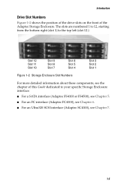
... the bottom right (slot 1) to your specific Storage Enclosure interface: ■ For a SATA interface (Adaptec FS4100 or FS4500), see Chapter 5. ■ For an FC interface (Adaptec FC4100), see Chapter 6. ■ For an Ultra320 SCSI interface (Adaptec SC4100), see Chapter 7. 1-5 Introduction Drive Slot Numbers Figure 1-2 shows the position of the drive slots on the front of this Guide...
... the bottom right (slot 1) to your specific Storage Enclosure interface: ■ For a SATA interface (Adaptec FS4100 or FS4500), see Chapter 5. ■ For an FC interface (Adaptec FC4100), see Chapter 6. ■ For an Ultra320 SCSI interface (Adaptec SC4100), see Chapter 7. 1-5 Introduction Drive Slot Numbers Figure 1-2 shows the position of the drive slots on the front of this Guide...
User Guide
Page 19
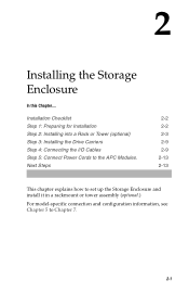
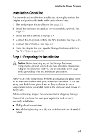
Next Steps 2-2 2-2 2-3 2-9 2-9 2-13 2-13 This chapter explains how to set up the Storage Enclosure and install it in a rackmount or tower assembly (optional.) For model-specific connection and configuration information, see Chapter 5 to the APC Modules. Installation Checklist Step 1: Preparing for Installation Step 2: Installing into a Rack or Tower (optional) Step 3: Installing the Drive Carriers Step 4: Connecting the I/O Cables Step 5: Connect Power Cords to Chapter 7. 2-1 2 Installing the Storage Enclosure In this Chapter....
Next Steps 2-2 2-2 2-3 2-9 2-9 2-13 2-13 This chapter explains how to set up the Storage Enclosure and install it in a rackmount or tower assembly (optional.) For model-specific connection and configuration information, see Chapter 5 to the APC Modules. Installation Checklist Step 1: Preparing for Installation Step 2: Installing into a Rack or Tower (optional) Step 3: Installing the Drive Carriers Step 4: Connecting the I/O Cables Step 5: Connect Power Cords to Chapter 7. 2-1 2 Installing the Storage Enclosure In this Chapter....
User Guide
Page 20
... antistatic precautions. Before continuing, inspect the components for Installation ! See page 2-2. 2 Install the enclosure in a rack or tower assembly (optional.) See page 2-3. 3 Install the drive carriers. Adaptec recommends that you install them on page 2-13. If you are ready to the chapter for your rack does not have the tools you require... and trouble-free installation, thoroughly review this chapter and perform the tasks in the order shown here: 1 Plan and prepare for tightening nuts (if your specific Storage Enclosure interface.
... antistatic precautions. Before continuing, inspect the components for Installation ! See page 2-2. 2 Install the enclosure in a rack or tower assembly (optional.) See page 2-3. 3 Install the drive carriers. Adaptec recommends that you install them on page 2-13. If you are ready to the chapter for your rack does not have the tools you require... and trouble-free installation, thoroughly review this chapter and perform the tasks in the order shown here: 1 Plan and prepare for tightening nuts (if your specific Storage Enclosure interface.
User Guide
Page 27
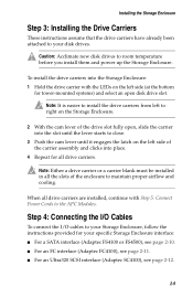
... all the slots of the carrier assembly and clicks into the Storage Enclosure: 1 Hold the drive carrier with Step 5: Connect Power Cords to your specific Storage Enclosure interface: ■ For a SATA interface (Adaptec FS4100 or FS4500), see page 2-10. ■ For an FC interface (Adaptec FC4100), see page 2-11. ■ For an Ultra320 SCSI interface...
... all the slots of the carrier assembly and clicks into the Storage Enclosure: 1 Hold the drive carrier with Step 5: Connect Power Cords to your specific Storage Enclosure interface: ■ For a SATA interface (Adaptec FS4100 or FS4500), see page 2-10. ■ For an FC interface (Adaptec FC4100), see page 2-11. ■ For an Ultra320 SCSI interface...
User Guide
Page 31
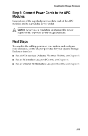
... and to the APC Modules. Caution: Always use a regulating uninterruptible power supply (UPS) to protect your specific Storage Enclosure interface: ■ For a SATA interface (Adaptec FS4100 or FS4500), see Chapter 5. ■ For an FC interface (Adaptec FC4100), see Chapter 6. ■ For an Ultra320 SCSI interface (Adaptec SC4100), see the chapter provided for your Storage Enclosure.
... and to the APC Modules. Caution: Always use a regulating uninterruptible power supply (UPS) to protect your specific Storage Enclosure interface: ■ For a SATA interface (Adaptec FS4100 or FS4500), see Chapter 5. ■ For an FC interface (Adaptec FC4100), see Chapter 6. ■ For an Ultra320 SCSI interface (Adaptec SC4100), see the chapter provided for your Storage Enclosure.
User Guide
Page 34
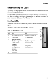
...Monitoring Understanding the LEDs This section explains the LEDs used 3-3 The LEDs function as described in this Guide that's dedicated to the specific interface for your Storage Enclosure. Table 3-1 Front Panel LEDs LED 1 LED On Off 1 Enclosure power on the front panel of ... (Chapter 5 to Chapter 7.) Front Panel LEDs There are four LEDs on Enclosure power off 2 3 2 Shelf fault No shelf fault 3 FS4100/FS4500: 4 Enclosure speed is Enclosure speed is 3 GB/second 1.5 GB/second SC4100: Split-bus configuration Joined-bus configuration FC4100: Not used 4 Not used...
...Monitoring Understanding the LEDs This section explains the LEDs used 3-3 The LEDs function as described in this Guide that's dedicated to the specific interface for your Storage Enclosure. Table 3-1 Front Panel LEDs LED 1 LED On Off 1 Enclosure power on the front panel of ... (Chapter 5 to Chapter 7.) Front Panel LEDs There are four LEDs on Enclosure power off 2 3 2 Shelf fault No shelf fault 3 FS4100/FS4500: 4 Enclosure speed is Enclosure speed is 3 GB/second 1.5 GB/second SC4100: Split-bus configuration Joined-bus configuration FC4100: Not used 4 Not used...
User Guide
Page 44
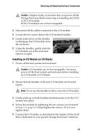
... to hot-swap SCSI I/O modules. ! A blank I /O module configurations. (For detailed information about your specific interface: ■ For a SATA interface (Adaptec FS4100 or FS4500), see Chapter 5. ■ For an FC interface (Adaptec FC4100), see Chapter 6. ■ For an Ultra320 SCSI interface (Adaptec SC4100), see Chapter 7. To maintain proper airflow and cooling, either an I/O module or an...
... to hot-swap SCSI I/O modules. ! A blank I /O module configurations. (For detailed information about your specific interface: ■ For a SATA interface (Adaptec FS4100 or FS4500), see Chapter 5. ■ For an FC interface (Adaptec FC4100), see Chapter 6. ■ For an Ultra320 SCSI interface (Adaptec SC4100), see Chapter 7. To maintain proper airflow and cooling, either an I/O module or an...
User Guide
Page 45
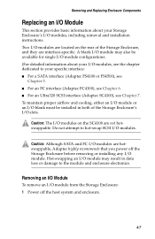
... the I/O module. 3 Gently push up on both handles simultaneously to fix the I /O cables, as described in Step 3 on the handles to your specific Storage Enclosure's interface: 4-8 Do not overtighten them. 5 Connect the I /O module into place. 4 Secure the module by tightening the two screws you... disengage the I/O module from the enclosure. 5 Using the handles, gently slide the I/O module out of the new I /O module. Caution: Adaptec highly recommends that the handles of the enclosure (shown at right). Removing and Replacing Enclosure Components ! You must power off the host system and...
... the I/O module. 3 Gently push up on both handles simultaneously to fix the I /O cables, as described in Step 3 on the handles to your specific Storage Enclosure's interface: 4-8 Do not overtighten them. 5 Connect the I /O module into place. 4 Secure the module by tightening the two screws you... disengage the I/O module from the enclosure. 5 Using the handles, gently slide the I/O module out of the new I /O module. Caution: Adaptec highly recommends that the handles of the enclosure (shown at right). Removing and Replacing Enclosure Components ! You must power off the host system and...
User Guide
Page 53
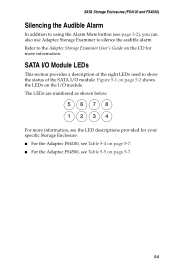
...the CD for more information, see the LED descriptions provided for your specific Storage Enclosure: ■ For the Adaptec FS4100, see Table 5-4 on page 5-7. ■ For the Adaptec FS4500, see page 3-2), you can also use Adaptec Storage Examiner to silence the audible alarm. The LEDs are numbered as... shown below. 5678 1234 For more information. SATA Storage Enclosures (FS4100 and FS4500) Silencing the Audible Alarm In addition to ...
...the CD for more information, see the LED descriptions provided for your specific Storage Enclosure: ■ For the Adaptec FS4100, see Table 5-4 on page 5-7. ■ For the Adaptec FS4500, see page 3-2), you can also use Adaptec Storage Examiner to silence the audible alarm. The LEDs are numbered as... shown below. 5678 1234 For more information. SATA Storage Enclosures (FS4100 and FS4500) Silencing the Audible Alarm In addition to ...
User Guide
Page 70
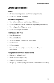
General Specifications 8-2 Ultra320 SCSI Storage Enclosure Technical Specifications 8-5 SATA Storage Enclosure Technical Specifications 8-7 FC Storage Enclosure Technical Specifications 8-9 8-1 8 Technical Specifications In this Chapter....
General Specifications 8-2 Ultra320 SCSI Storage Enclosure Technical Specifications 8-5 SATA Storage Enclosure Technical Specifications 8-7 FC Storage Enclosure Technical Specifications 8-9 8-1 8 Technical Specifications In this Chapter....
User Guide
Page 71
...(8.9 cm) ■ Width: 17.6 inches (44.7 cm) ■ Depth: 19.5 inches (49.5 cm) ■ Weight: up to 12 drives per enclosure Redundant Components ■ Two Advanced Power and Cooling (APC) units ■ Up to two RAID or JBOD controllers (depending on interface) ■...Up to 60 lbs (27 kg) maximum (with all drives installed) 8-2 Technical Specifications General Specifications System ■ 2U enclosure height (rack and tower configurations) ■ Up to 12 drives per enclosure Field Replaceable Units ■ Disk drive carriers ■ Disk carrier blanks ■ Advanced Power and...
...(8.9 cm) ■ Width: 17.6 inches (44.7 cm) ■ Depth: 19.5 inches (49.5 cm) ■ Weight: up to 12 drives per enclosure Redundant Components ■ Two Advanced Power and Cooling (APC) units ■ Up to two RAID or JBOD controllers (depending on interface) ■...Up to 60 lbs (27 kg) maximum (with all drives installed) 8-2 Technical Specifications General Specifications System ■ 2U enclosure height (rack and tower configurations) ■ Up to 12 drives per enclosure Field Replaceable Units ■ Disk drive carriers ■ Disk carrier blanks ■ Advanced Power and...
User Guide
Page 72
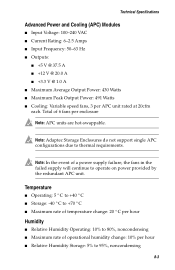
...9632; Storage: -40 ° C to +70 ° C ■ Maximum rate of temperature change: 20 ° C per APC unit rated at 20cfm each. Technical Specifications Advanced Power and Cooling (APC) Modules ■ Input Voltage: 100-240 VAC ■ Current Rating: 6-2.5 Amps ■ Input Frequency: 50-63 Hz ■ Outputs: &#...noncondensing 8-3 Note: In the event of a power supply failure, the fans in the failed supply will continue to thermal requirements. Note: Adaptec Storage Enclosures do not support single APC configurations due to operate on power provided by the redundant APC unit.
...9632; Storage: -40 ° C to +70 ° C ■ Maximum rate of temperature change: 20 ° C per APC unit rated at 20cfm each. Technical Specifications Advanced Power and Cooling (APC) Modules ■ Input Voltage: 100-240 VAC ■ Current Rating: 6-2.5 Amps ■ Input Frequency: 50-63 Hz ■ Outputs: &#...noncondensing 8-3 Note: In the event of a power supply failure, the fans in the failed supply will continue to thermal requirements. Note: Adaptec Storage Enclosures do not support single APC configurations due to operate on power provided by the redundant APC unit.
User Guide
Page 73
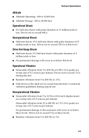
...damage will occur at or below this level. Drives not to exceed 60Gs. Nonoperational Vibration ■ Sinusoidal vibration from 5 to 40,000 feet Operational Shock ■ 8 G half sine shock with pulse duration of 11 milliseconds or less. Technical Specifications Altitude ■ Altitude Operating: -200 to 10...,000 feet ■ Altitude Storage: -200 to 22 Hz at 0.06-inch displacement at a sweep rate of 0.5 octaves per minute. Drives not to exceed 350 Gs at this level....
...damage will occur at or below this level. Drives not to exceed 60Gs. Nonoperational Vibration ■ Sinusoidal vibration from 5 to 40,000 feet Operational Shock ■ 8 G half sine shock with pulse duration of 11 milliseconds or less. Technical Specifications Altitude ■ Altitude Operating: -200 to 10...,000 feet ■ Altitude Storage: -200 to 22 Hz at 0.06-inch displacement at a sweep rate of 0.5 octaves per minute. Drives not to exceed 350 Gs at this level....
User Guide
Page 74
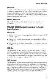
..., hot swap, and direct attach U160 or U320 disk drives. ■ The disk drives are direct connected to the midplane via 80-pin SCA-2 connectors. Technical Specifications Acoustics Acoustic level shall not exceed a weighted sound power of 640 MB/sec. 8-5 SCSI Midplane The Adaptec SCSI Storage Enclosure backplanes contain no fault conditions. SCSI Bus...
..., hot swap, and direct attach U160 or U320 disk drives. ■ The disk drives are direct connected to the midplane via 80-pin SCA-2 connectors. Technical Specifications Acoustics Acoustic level shall not exceed a weighted sound power of 640 MB/sec. 8-5 SCSI Midplane The Adaptec SCSI Storage Enclosure backplanes contain no fault conditions. SCSI Bus...
User Guide
Page 75
... IDs 0 to 5 and 8 to 13. There is 280MB/560MB. The I /O module connectors on the rear of the midplane. I/O Modules The Adaptec U320 SCSI midplane has two I /O modules connect to 5. 8-6 Technical Specifications Note: Note: Actual real-world bandwidth is also a connector for the Enclosure Services (ES) module. ■ The ES module monitors and...
... IDs 0 to 5 and 8 to 13. There is 280MB/560MB. The I /O module connectors on the rear of the midplane. I/O Modules The Adaptec U320 SCSI midplane has two I /O modules connect to 5. 8-6 Technical Specifications Note: Note: Actual real-world bandwidth is also a connector for the Enclosure Services (ES) module. ■ The ES module monitors and...