User Manual
Page 1
adaptec, inc. AHA-1540 User's Manual AT-to-SCSI Host Adapter
adaptec, inc. AHA-1540 User's Manual AT-to-SCSI Host Adapter
User Manual
Page 2
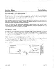
...-1 J6 J8 J5 J7 J1 LED J4 J9 RN6 RN7 J10 O F1 S S C C S S AHA-1540 3 - 1 adaptec NOTE: The AHA-1540, like all electronic equipment is configured and ready to a SCSI target. Please take the proper precautions when handling the board. In case of setting the various on-board jumpers... are the functions of the equipment to SCSI host adapter. Keep the board in your freight company representative so that the necessary insurance claims can be initiated. The following section details the installation procedure for the Adaptec AHA-1540 AT to the factory necessary. Section Three...
...-1 J6 J8 J5 J7 J1 LED J4 J9 RN6 RN7 J10 O F1 S S C C S S AHA-1540 3 - 1 adaptec NOTE: The AHA-1540, like all electronic equipment is configured and ready to a SCSI target. Please take the proper precautions when handling the board. In case of setting the various on-board jumpers... are the functions of the equipment to SCSI host adapter. Keep the board in your freight company representative so that the necessary insurance claims can be initiated. The following section details the installation procedure for the Adaptec AHA-1540 AT to the factory necessary. Section Three...

User Manual
Page 3
... XX 1 X- X 2 - -X 3 X X- 4 - Pin pair 1 is the left most pair of pins. AHA-1540 3 - 2 adaptec Section Three Installation 3.2.1 SCSI Jumper Configuration Jumper set J1, pin pair 3, is the parity enable/disable jumper. The SCSI address consists of pin pairs 4, 5, and 6 in the large block of jumper pins located in the upper... corner of the PCB. The SCSI address is 7. The SCSI parity jumper, pin pair 3 is not the first or the last SCSI device in a string of SCSI devices, or if in the upper right hand corner of the PCB. If the AHA-1540 is located in the large block...
... XX 1 X- X 2 - -X 3 X X- 4 - Pin pair 1 is the left most pair of pins. AHA-1540 3 - 2 adaptec Section Three Installation 3.2.1 SCSI Jumper Configuration Jumper set J1, pin pair 3, is the parity enable/disable jumper. The SCSI address consists of pin pairs 4, 5, and 6 in the large block of jumper pins located in the upper... corner of the PCB. The SCSI address is 7. The SCSI parity jumper, pin pair 3 is not the first or the last SCSI device in a string of SCSI devices, or if in the upper right hand corner of the PCB. If the AHA-1540 is located in the large block...

User Manual
Page 4
... 7 X = Jumper Installed J1 7 8 0 0 0 0 0 0 0 X 0 0 0 0 0 0 0 0 0 0 X 0 0 0 pin pair 1 AHA-1540 3 - 3 adaptec J1 3 0 0 0 0 0 0 0 0 0 0 0 0 0 0 0 0 0 0 0 0 0 0 pin pair 1 The AHA-1540 will still support synchronous SCSI transfers, but the target must initiate the negotiation. Default is the left most pair of the printed circuit board. This jumper...be removed. Default is the leftmost pair of the PCB. Section Three Installation 3.2.4 SCSI Terminator Power Fuse, Fl, controls the terminator power. Pin pair 1 is jumper removed, synchronous negotiation initiation disabled....
... 7 X = Jumper Installed J1 7 8 0 0 0 0 0 0 0 X 0 0 0 0 0 0 0 0 0 0 X 0 0 0 pin pair 1 AHA-1540 3 - 3 adaptec J1 3 0 0 0 0 0 0 0 0 0 0 0 0 0 0 0 0 0 0 0 0 0 0 pin pair 1 The AHA-1540 will still support synchronous SCSI transfers, but the target must initiate the negotiation. Default is the left most pair of the printed circuit board. This jumper...be removed. Default is the leftmost pair of the PCB. Section Three Installation 3.2.4 SCSI Terminator Power Fuse, Fl, controls the terminator power. Pin pair 1 is jumper removed, synchronous negotiation initiation disabled....
User Manual
Page 5
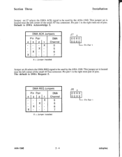
...- X X - - - This jumper set is located near the left corner of the small AT bus connector. Pin Pair 4 3 21 X X X X DMA Channel 0 5 6 7 X = Jumper Installed J6 2 0 0 X 0 0 0 X 0 Pin Pair 1 AHA-1540 3 - 4 adaptec This jumper set is located near the left corner of the small AT bus connector. Pin pair 1 is the right most set of pins. The... Pin pair 1 is the right most pair of pins. Section Three Installation Jumper set J7 selects the DMA ACK signal to be used by the AHA-1540. Pin Pair 1 Jumper set J6 selects the DMA REQ signal to be used by the...
...- X X - - - This jumper set is located near the left corner of the small AT bus connector. Pin Pair 4 3 21 X X X X DMA Channel 0 5 6 7 X = Jumper Installed J6 2 0 0 X 0 0 0 X 0 Pin Pair 1 AHA-1540 3 - 4 adaptec This jumper set is located near the left corner of the small AT bus connector. Pin pair 1 is the right most set of pins. The... Pin pair 1 is the right most pair of pins. Section Three Installation Jumper set J7 selects the DMA ACK signal to be used by the AHA-1540. Pin Pair 1 Jumper set J6 selects the DMA REQ signal to be used by the...
User Manual
Page 6
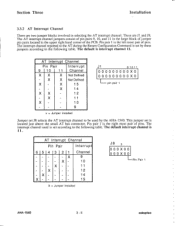
... jumper set J8 selects the AT interrupt channel to the following table. AT Interrupt Channel Pin Pair Interrupt 654 3 21 Channel 9 10 11 12 14 15 X = Jumper Installed J8 3 0 0 0 X 0 0 0 0 0 X 0 0 I-Pin Pair 1 AHA-1540 3 - 5 adaptec Section Three Installation 3.3.2 AT Interrupt Channel There are J1 and J8. Pin pair 1 is located just above the small AT...
... jumper set J8 selects the AT interrupt channel to the following table. AT Interrupt Channel Pin Pair Interrupt 654 3 21 Channel 9 10 11 12 14 15 X = Jumper Installed J8 3 0 0 0 X 0 0 0 0 0 X 0 0 I-Pin Pair 1 AHA-1540 3 - 5 adaptec Section Three Installation 3.3.2 AT Interrupt Channel There are J1 and J8. Pin pair 1 is located just above the small AT...
User Manual
Page 7
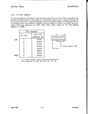
... not be changed unless a new BIOS is selected by the jumpers in jumper block J9. Valid Addresses Are: 334, 330, 234, 230, 134, 130 AHA-1540 3 - 6 adaptec Section Three Installation 3.3.3 AT Port Address The starting address of the block of pins. LSB MSB Port Address Pin Pair 1 2 3 4 5 6 7 ...8 Port I /O ports required by the AHA-1540 is supplied. The default address is located just above the left most pair of four I /O Address Bit 004H 008H 010H 020H 040H 080H 100H 200H 3 4 ...
... not be changed unless a new BIOS is selected by the jumpers in jumper block J9. Valid Addresses Are: 334, 330, 234, 230, 134, 130 AHA-1540 3 - 6 adaptec Section Three Installation 3.3.3 AT Port Address The starting address of the block of pins. LSB MSB Port Address Pin Pair 1 2 3 4 5 6 7 ...8 Port I /O ports required by the AHA-1540 is supplied. The default address is located just above the left most pair of four I /O Address Bit 004H 008H 010H 020H 040H 080H 100H 200H 3 4 ...

User Manual
Page 8
...shunts installed. X X- -- - This jumper set is necessary to change the state of this jumper after the system has been configured, the SCSI hard disk must not have one wait state added by the jumper pins located in the system. The default is no jumper installed. 3.3.7 ...and LA19 and SA19 together. The default address is jumper installed. Default is ODCOOOH. AHA-1540 3- 7 adaptec Default is prevented. Contact your system manufacturer if in immediate system problems. If it is located to the Adaptec BIOS can have any other BIOS in J10. AT BIOS Address Pin Pair 12 3 ...
...shunts installed. X X- -- - This jumper set is necessary to change the state of this jumper after the system has been configured, the SCSI hard disk must not have one wait state added by the jumper pins located in the system. The default is no jumper installed. 3.3.7 ...and LA19 and SA19 together. The default address is jumper installed. Default is ODCOOOH. AHA-1540 3- 7 adaptec Default is prevented. Contact your system manufacturer if in immediate system problems. If it is located to the Adaptec BIOS can have any other BIOS in J10. AT BIOS Address Pin Pair 12 3 ...
