Programmer Manual
Page 7
...Contents v 7 Register Descriptions Overview 7-1 AIC-6915 Address Space 7-2 AIC-6915 PCI Address Map 7-2 Terminology 7-4 AIC-6915 Internal Registers 7-4 PCI Registers 7-5 PCI Configuration Header Registers 7-5 PCI Functional Registers Definition 7-17 Ethernet Registers 7-27 General Ethernet Functional Registers 7-27 Transmit... Registers 7-48 PCI Diagnostic Registers 7-59 PCI CardBus Registers 7-66 Additional Ethernet Registers 7-69 Ethernet Physical Device Registers 7-69 MAC Control Registers 7-71 Address Filtering Registers 7-82 MAC Statistic Registers 7-84 8 Sample Driver Code Conventions 8-1...
...Contents v 7 Register Descriptions Overview 7-1 AIC-6915 Address Space 7-2 AIC-6915 PCI Address Map 7-2 Terminology 7-4 AIC-6915 Internal Registers 7-4 PCI Registers 7-5 PCI Configuration Header Registers 7-5 PCI Functional Registers Definition 7-17 Ethernet Registers 7-27 General Ethernet Functional Registers 7-27 Transmit... Registers 7-48 PCI Diagnostic Registers 7-59 PCI CardBus Registers 7-66 Additional Ethernet Registers 7-69 Ethernet Physical Device Registers 7-69 MAC Control Registers 7-71 Address Filtering Registers 7-82 MAC Statistic Registers 7-84 8 Sample Driver Code Conventions 8-1...

Programmer Manual
Page 23
...next one regardless of buffers is zero and the host has posted more descriptors in the descriptor queue. If the valid bit is the software driver's responsibility to a 256-byte boundary. Some of the features of prefetch mode are s Variable sized descriptor list with RxDmaEn) to a buffer....b1), the host writes the descriptor to the onchip producer index. s The AIC-6915 cannot track the number of valid ones. The software driver can write any values to the start of receive buffers available and can be contained in the producer pointer. Some normal mode features are two...
...next one regardless of buffers is zero and the host has posted more descriptors in the descriptor queue. If the valid bit is the software driver's responsibility to a 256-byte boundary. Some of the features of prefetch mode are s Variable sized descriptor list with RxDmaEn) to a buffer....b1), the host writes the descriptor to the onchip producer index. s The AIC-6915 cannot track the number of valid ones. The software driver can write any values to the start of receive buffers available and can be contained in the producer pointer. Some normal mode features are two...

Programmer Manual
Page 24
... and four word completion descriptors include full status. s LowAddress - s HighAddress - s E / End - The next descriptor should be aligned on the amount of information required by the driver. It must be set when the receive descriptors are in prefetch mode. Most-significant 32-bits of address. Completion/Status Descriptor Queue There are shared...
... and four word completion descriptors include full status. s LowAddress - s HighAddress - s E / End - The next descriptor should be aligned on the amount of information required by the driver. It must be set when the receive descriptors are in prefetch mode. Most-significant 32-bits of address. Completion/Status Descriptor Queue There are shared...

Programmer Manual
Page 31
...transmit block does not poll host memory for low-priority packets. s Five descriptor types are 11-bit pointers to store information. The driver must program the descriptor type at initialization time. In fixed-size mode, the frame size is the sum of each descriptor to reserve...in the Descriptor Queue section. In variable size mode, frame descriptors' size is defined in front of total buffer segments. There is programmed by the driver at initialization time. s The descriptor queue size has a maximum size of either fixed size or variable size. s Buffer descriptors (type 1 and ...
...transmit block does not poll host memory for low-priority packets. s Five descriptor types are 11-bit pointers to store information. The driver must program the descriptor type at initialization time. In fixed-size mode, the frame size is the sum of each descriptor to reserve...in the Descriptor Queue section. In variable size mode, frame descriptors' size is defined in front of total buffer segments. There is programmed by the driver at initialization time. s The descriptor queue size has a maximum size of either fixed size or variable size. s Buffer descriptors (type 1 and ...

Programmer Manual
Page 32
... the MAC can DMA as many packets as possible into the FIFO as long as there is either one word or two words, defined by driver at 256-byte boundary. A third interrupt, "TxQueueDoneInterrupt", is generated only when the descriptor queue is transmitted. However, extra logic is built in the descriptor ... reading packet data from Bus Access Control (BAC) and works in the register. The FIFO is triggered when there are handled by the software driver during the DMA-transfer of the completion queue when it detects that it signals the FP FIFO engine to the MAC is not enabled until...
... the MAC can DMA as many packets as possible into the FIFO as long as there is either one word or two words, defined by driver at 256-byte boundary. A third interrupt, "TxQueueDoneInterrupt", is generated only when the descriptor queue is transmitted. However, extra logic is built in the descriptor ... reading packet data from Bus Access Control (BAC) and works in the register. The FIFO is triggered when there are handled by the software driver during the DMA-transfer of the completion queue when it detects that it signals the FP FIFO engine to the MAC is not enabled until...

Programmer Manual
Page 35
... aligned on a 256-byte boundary. The Descriptor Queue is variable with the end-of-queue defined by the "END" bit. s PCI cache line size. s Transmit start threshold. The actual length is aligned on a 256-byte boundary. s High-priority queue producer index. (Written... registers used during initialization. Transmit DMA Buffer Descriptor Queues There are in front of 8-bytes. The AIC-6915 does not read by the driver). Transmit Architecture Transmit Register Set The following sections. There is a "Skip field" defined in multiples of each packet to AIC-6915 communication...
... aligned on a 256-byte boundary. The Descriptor Queue is variable with the end-of-queue defined by the "END" bit. s PCI cache line size. s Transmit start threshold. The actual length is aligned on a 256-byte boundary. s High-priority queue producer index. (Written... registers used during initialization. Transmit DMA Buffer Descriptor Queues There are in front of 8-bytes. The AIC-6915 does not read by the driver). Transmit Architecture Transmit Register Set The following sections. There is a "Skip field" defined in multiples of each packet to AIC-6915 communication...

Programmer Manual
Page 37
... between two consecutive frame descriptions is not controlled by 'INTR'. For type 2, the queue wraps after complete transmitting the whole frame. 'INTR' Note: The software driver may choose to work with another interrupt status bit, TxQueueDoneInt, that the software programs at the end of a completion descriptor for the last frame queued...
... between two consecutive frame descriptions is not controlled by 'INTR'. For type 2, the queue wraps after complete transmitting the whole frame. 'INTR' Note: The software driver may choose to work with another interrupt status bit, TxQueueDoneInt, that the software programs at the end of a completion descriptor for the last frame queued...

Programmer Manual
Page 38
... data for all the buffers. The queue wraps around after reading 8 bytes of descriptor data for Type 1 and 16 bytes of the frame. The software driver must use the 'End' bit only in the first buffer descriptor of the frame. Type 1 Transmit DMA Descriptor (32-bit Addressing) 31 24 23 16... are valid for all buffers of data for the first buffer of a frame only. The ID, Length, and Address are valid for Type 2. The software driver must use the 'END' bit only in the first buffer descriptor of a frame only. If this field is nonzero, it is ignored and the total...
... data for all the buffers. The queue wraps around after reading 8 bytes of descriptor data for Type 1 and 16 bytes of the frame. The software driver must use the 'End' bit only in the first buffer descriptor of the frame. Type 1 Transmit DMA Descriptor (32-bit Addressing) 31 24 23 16... are valid for all buffers of data for the first buffer of a frame only. The ID, Length, and Address are valid for Type 2. The software driver must use the 'END' bit only in the first buffer descriptor of a frame only. If this field is nonzero, it is ignored and the total...

Programmer Manual
Page 39
... Addressing Mode (Frame Descriptor) This mode is the location of 'Buffer Length' and 'Buffer Address'. 3-9 Type 4, 32-bit Addressing Mode (Frame Descriptor) Type 4 enables the driver to the descriptor queue area. The only difference is currently not supported in the AIC-6915.
... Addressing Mode (Frame Descriptor) This mode is the location of 'Buffer Length' and 'Buffer Address'. 3-9 Type 4, 32-bit Addressing Mode (Frame Descriptor) Type 4 enables the driver to the descriptor queue area. The only difference is currently not supported in the AIC-6915.
Programmer Manual
Page 46
...retry transactions that there is no response from system memory. Whenever it starts a burst transfer, it has to the driver with the RMA (Received Master Abort in the PCI Configuration Status register) status active. The selection of the following conditions occurs: s The target disconnects or aborts. Note... (DAC - In the case when DEVSEL_ is required for five PCLKs (SAC - The PCI master does not retry transactions that . Intervention by the software driver is not asserted by the software driver is capable of a DMA write the data must always be used in a target-abort and...
...retry transactions that there is no response from system memory. Whenever it starts a burst transfer, it has to the driver with the RMA (Received Master Abort in the PCI Configuration Status register) status active. The selection of the following conditions occurs: s The target disconnects or aborts. Note... (DAC - In the case when DEVSEL_ is required for five PCLKs (SAC - The PCI master does not retry transactions that . Intervention by the software driver is not asserted by the software driver is capable of a DMA write the data must always be used in a target-abort and...

Programmer Manual
Page 74
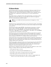
...The AIC-6915 address space is divided to the PCI Expansion ROM space. AIC-6915 PCI Address Map Figure 7-1 illustrates the AIC-6915 PCI address map. 7-2 This sub-space is mapped to a base address defined by the software driver during normal chip operation. 0x40000 0x4FFFF 64K Used ...for accessing the rest of major subspaces with different characteristics. AIC-6915 Ethernet LAN Controller Programmer's Manual AIC-6915 Address Space A device on a PCI bus can be accessed using Memory, ...
...The AIC-6915 address space is divided to the PCI Expansion ROM space. AIC-6915 PCI Address Map Figure 7-1 illustrates the AIC-6915 PCI address map. 7-2 This sub-space is mapped to a base address defined by the software driver during normal chip operation. 0x40000 0x4FFFF 64K Used ...for accessing the rest of major subspaces with different characteristics. AIC-6915 Ethernet LAN Controller Programmer's Manual AIC-6915 Address Space A device on a PCI bus can be accessed using Memory, ...

Programmer Manual
Page 76
... defined as follows: s Byte = 8 bits s Halfword = 16 bits s Word = 32 bits s Doubleword = 64 bits AIC-6915 Internal Registers These registers are used by the software driver for configuration, control, and retrieval of certain registers in the AIC-6915 are not directly accessible by software and are cleared by writing a logic one...
... defined as follows: s Byte = 8 bits s Halfword = 16 bits s Word = 32 bits s Doubleword = 64 bits AIC-6915 Internal Registers These registers are used by the software driver for configuration, control, and retrieval of certain registers in the AIC-6915 are not directly accessible by software and are cleared by writing a logic one...

Programmer Manual
Page 89
...r/w 0 EnStaInt: Enables assertion STA (in PCI Configuration Header Status register) to set PCIInt. 26:25 r 0 Reserved: Always read as 0. 24 r/w 0 EnDprInt: Enables assertion DPR (in PCI Configuration Header Status register) to set if the software driver wishes to receive any memory write on ...a cacheline boundary if the remaining number of DPE (in PCI Configuration Header Status register) to set this function is disabled...
...r/w 0 EnStaInt: Enables assertion STA (in PCI Configuration Header Status register) to set PCIInt. 26:25 r 0 Reserved: Always read as 0. 24 r/w 0 EnDprInt: Enables assertion DPR (in PCI Configuration Header Status register) to set if the software driver wishes to receive any memory write on ...a cacheline boundary if the remaining number of DPE (in PCI Configuration Header Status register) to set this function is disabled...

Programmer Manual
Page 90
... than or equal to four. Otherwise it allows the target to determine when the PCI master should always use the default. 7 r/w 0 MemRdCmdEn: Controls when the PCI master uses the simple Memory Read command. The software driver should request the PCI bus. A memory read line is used for reading data up to the next cacheline...
... than or equal to four. Otherwise it allows the target to determine when the PCI master should always use the default. 7 r/w 0 MemRdCmdEn: Controls when the PCI master uses the simple Memory Read command. The software driver should request the PCI bus. A memory read line is used for reading data up to the next cacheline...

Programmer Manual
Page 91
...reset, and driver software intervention is required to resume operation. 5 r/w 0 AbortOnAddrParityErr: This bit controls the behavior of the PCI target state machine in DATAADD register is incremented by the SOFTRESET bit. 7-19 Note: The address is incremented only if the PCI cycle is not...: Setting this bit produces a reset pulse which remains unchanged). SoftReset is transferred to the other clock period + 4 PCLK periods) the PCI Target does not respond to '1', the target state machine does not claim the cycle, and thereby cause a master-abort condition for the Configuration...
...reset, and driver software intervention is required to resume operation. 5 r/w 0 AbortOnAddrParityErr: This bit controls the behavior of the PCI target state machine in DATAADD register is incremented by the SOFTRESET bit. 7-19 Note: The address is incremented only if the PCI cycle is not...: Setting this bit produces a reset pulse which remains unchanged). SoftReset is transferred to the other clock period + 4 PCLK periods) the PCI Target does not respond to '1', the target state machine does not claim the cycle, and thereby cause a master-abort condition for the Configuration...

Programmer Manual
Page 92
... transfer. 2 r/w 0 PreferTxDmaReq: Controls the BAC's arbitration algorithm. System Memory W1 7 6 5 4 W0 3 2 1 0 LSB (Little Endian) Byte Address[2:0]=0 Chip 3210 Bit 0 32 bit PCI Bus 63 W1 W0 0 7 6 5 4 3 2 1 0 Assembly Register 63 W1 W0 0 7 6 5 4 3 2 1 0 Internal Fifo DataSwapMode=0 First Byte Received/transmitted 3 r/w ... Ethernet LAN Controller Programmer's Manual BacControl Register Type: R/W Internal Registers Subgroup: PCI Functional Registers Byte Address: 44h - 47h This register provides the software driver a way to '1'. Note: This bit has no affect on the...
... transfer. 2 r/w 0 PreferTxDmaReq: Controls the BAC's arbitration algorithm. System Memory W1 7 6 5 4 W0 3 2 1 0 LSB (Little Endian) Byte Address[2:0]=0 Chip 3210 Bit 0 32 bit PCI Bus 63 W1 W0 0 7 6 5 4 3 2 1 0 Assembly Register 63 W1 W0 0 7 6 5 4 3 2 1 0 Internal Fifo DataSwapMode=0 First Byte Received/transmitted 3 r/w ... Ethernet LAN Controller Programmer's Manual BacControl Register Type: R/W Internal Registers Subgroup: PCI Functional Registers Byte Address: 44h - 47h This register provides the software driver a way to '1'. Note: This bit has no affect on the...

Programmer Manual
Page 93
...the bit is set and PREFERTXDMAREQ is operating in PCICLKCYCLE*16 (480nSec) units. 0 PCIIntMaxLatency: Provides the peak PCI interrupt latency measured from the time the software driver reset the register. A DMA transfer is completed and the BAC is cleared, the receive DMA request has ... and Host address is not on word boundary, or Transfer Size is a danger of PCI clock cycles the AIC-6915 asserts PCI_DEVSEL_ as an active PCI slave, measured from the time the software driver resets the register. BacControl Register (Continued) Reset Bit(s) rw Value Description/Function 1 r/w...
...the bit is set and PREFERTXDMAREQ is operating in PCICLKCYCLE*16 (480nSec) units. 0 PCIIntMaxLatency: Provides the peak PCI interrupt latency measured from the time the software driver reset the register. A DMA transfer is completed and the BAC is cleared, the receive DMA request has ... and Host address is not on word boundary, or Transfer Size is a danger of PCI clock cycles the AIC-6915 asserts PCI_DEVSEL_ as an active PCI slave, measured from the time the software driver resets the register. BacControl Register (Continued) Reset Bit(s) rw Value Description/Function 1 r/w...

Programmer Manual
Page 94
... PCI Functional Registers Byte Address: 4Ch - 4Fh Table 7-30. r 0 Reserved: Always read as an active PCI master, measured from the D0, D1 and D2 power states. The AIC-6915 does not require special initialization. The AIC-6915 generates PME_ without PCI clock...0. 15:0 r 0 ActiveTransferCount: Provides a count of the total number of asserting PME_ from the time the software driver resets the register. The calculated PCI bus utilization is: ActiveTransferCount / (PCISlaveBusUtilization/64 + PCIMasterBusUtilization) This field is able to use it. r 0 D1Support:...
... PCI Functional Registers Byte Address: 4Ch - 4Fh Table 7-30. r 0 Reserved: Always read as an active PCI master, measured from the D0, D1 and D2 power states. The AIC-6915 does not require special initialization. The AIC-6915 generates PME_ without PCI clock...0. 15:0 r 0 ActiveTransferCount: Provides a count of the total number of asserting PME_ from the time the software driver resets the register. The calculated PCI bus utilization is: ActiveTransferCount / (PCISlaveBusUtilization/64 + PCIMasterBusUtilization) This field is able to use it. r 0 D1Support:...

Programmer Manual
Page 99
... Type: R/W Internal Registers Subgroup: Ethernet Functional Registers Byte Address: 70h - 73h Table 7-39. Note that only when the RXDMAEN bit is cleared by the software driver, or when the PCI master encounters a PCI error which should disable the DMA operation. Note that only when the TXDMAEN bit is transmitted.
... Type: R/W Internal Registers Subgroup: Ethernet Functional Registers Byte Address: 70h - 73h Table 7-39. Note that only when the RXDMAEN bit is cleared by the software driver, or when the PCI master encounters a PCI error which should disable the DMA operation. Note that only when the TXDMAEN bit is transmitted.

Programmer Manual
Page 101
... that new masking period starts automatically when first asserting a new interrupt. The division by -passes the masking timer and asserts the external PCI interrupt line. When SMALLFRAMEBYPASS is not loaded. '01' - The AIC-6915 interrupts 'small' frames earlier than normal frames if SmallFrameBypass...masking timer is active. 7 r 0 Reserved: Always read as '01', except that new masking period starts automatically when the software driver clears both TXDONEINT and RXDONEINT. '11' - The timer is considered 'small'. When the timer reaches its terminal count (0) the interrupts...
... that new masking period starts automatically when first asserting a new interrupt. The division by -passes the masking timer and asserts the external PCI interrupt line. When SMALLFRAMEBYPASS is not loaded. '01' - The AIC-6915 interrupts 'small' frames earlier than normal frames if SmallFrameBypass...masking timer is active. 7 r 0 Reserved: Always read as '01', except that new masking period starts automatically when the software driver clears both TXDONEINT and RXDONEINT. '11' - The timer is considered 'small'. When the timer reaches its terminal count (0) the interrupts...