Aspire X1200 / X3200 Service Guide
Page 6
...web or channel. add-on your regional office MAY have a DIFFERENT part number code to -date information available on card, modem, or extra memory capability). If, for whatever reason, a part number change is made, it will NOT be noted in the printed Service Guide. vi These ...LOCALIZED FEATURES will not be covered in the FRU list of customer machines. For ACER-AUTHORIZED SERVICE PROVIDERS, your regional Acer office to the BASIC CONFIGURATION decided for repair and service of this generic service guide. FRU Information Please note WHEN...
...web or channel. add-on your regional office MAY have a DIFFERENT part number code to -date information available on card, modem, or extra memory capability). If, for whatever reason, a part number change is made, it will NOT be noted in the printed Service Guide. vi These ...LOCALIZED FEATURES will not be covered in the FRU list of customer machines. For ACER-AUTHORIZED SERVICE PROVIDERS, your regional Acer office to the BASIC CONFIGURATION decided for repair and service of this generic service guide. FRU Information Please note WHEN...
Aspire X1200 / X3200 Service Guide
Page 7
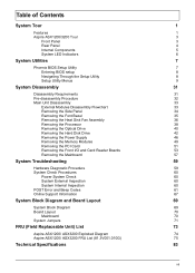
...Fan Assembly 36 Removing the Processor 38 Removing the Optical Drive 40 Removing the Hard Disk Drive 42 Removing the Power Supply 46 Removing the Memory Modules 49 Removing the PCI Card 51 Removing the Front I/O and Card Reader Boards 53 Removing the Mainboard 57 System Troubleshooting 59 Hardware ...Diagram and Board Layout 69 System Block Diagram 69 Board Layout 70 Mainboard 70 System Jumpers 71 FRU (Field Replaceable Unit) List 73 Aspire ASX1200/ ASX3200 Exploded Diagram 74 Aspire ASX1200/ ASX3200 FRU List (81.3V001.010G) 75 Technical Specifications 83 vii
...Fan Assembly 36 Removing the Processor 38 Removing the Optical Drive 40 Removing the Hard Disk Drive 42 Removing the Power Supply 46 Removing the Memory Modules 49 Removing the PCI Card 51 Removing the Front I/O and Card Reader Boards 53 Removing the Mainboard 57 System Troubleshooting 59 Hardware ...Diagram and Board Layout 69 System Block Diagram 69 Board Layout 70 Mainboard 70 System Jumpers 71 FRU (Field Replaceable Unit) List 73 Aspire ASX1200/ ASX3200 Exploded Diagram 74 Aspire ASX1200/ ASX3200 FRU List (81.3V001.010G) 75 Technical Specifications 83 vii
Aspire X1200 / X3200 Service Guide
Page 9
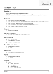
... T Supports up to two DDR2-667 registered ECC modules Media storage T DVD-ROM SATA drive T Super-Multi SATA DVD drive T 160 GB SATA hard disk drive Serial ATA controller T Embedded SATA2 controller T Two SATA ports Networking T One Gigabit Ethernet LAN port (RJ-45) PCI I/O T ...One PCI Express x16 bus slot T One PCI Express x1 bus slot I/O ports T Front t Three USB 2.0 ports t Memory Stick t Memory Stick PRO t Secure Digitial (SD) Card Chapter 1 1 Chapter 1 System Tour Features Below is a brief summary of the server depends on the model purchased.
... T Supports up to two DDR2-667 registered ECC modules Media storage T DVD-ROM SATA drive T Super-Multi SATA DVD drive T 160 GB SATA hard disk drive Serial ATA controller T Embedded SATA2 controller T Two SATA ports Networking T One Gigabit Ethernet LAN port (RJ-45) PCI I/O T ...One PCI Express x16 bus slot T One PCI Express x1 bus slot I/O ports T Front t Three USB 2.0 ports t Memory Stick t Memory Stick PRO t Secure Digitial (SD) Card Chapter 1 1 Chapter 1 System Tour Features Below is a brief summary of the server depends on the model purchased.
Aspire X1200 / X3200 Service Guide
Page 15
BIOS setup loads the configuration values in CMOS. This memory area is not part of the system RAM which allows configuration data to be retained when power is no need to make sure that you have saved all open files. NOTE: PhoenixBIOS ... utility under the following conditions. In this utility. Before you run this case, the system cannot retain configuration values in a battery-backed nonvolatile memory called CMOS RAM. The screenshots used in this guide display default system values. The system reboots immediately after you close the Setup. These values may be bad...
BIOS setup loads the configuration values in CMOS. This memory area is not part of the system RAM which allows configuration data to be retained when power is no need to make sure that you have saved all open files. NOTE: PhoenixBIOS ... utility under the following conditions. In this utility. Before you run this case, the system cannot retain configuration values in a battery-backed nonvolatile memory called CMOS RAM. The screenshots used in this guide display default system values. The system reboots immediately after you close the Setup. These values may be bad...
Aspire X1200 / X3200 Service Guide
Page 19
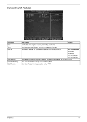
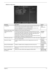
... All Errors All, But Diskette All, But Disk/Key Also called conventional memory. Total size of extended memory detected during POST Total size of system memory detected during the POST. Standard CMOS Features Parameter Date Time Halt On Base Memory Extended Memory Total Memory Description Option Set the date following the hour-minute-second format. Set...
... All Errors All, But Diskette All, But Disk/Key Also called conventional memory. Total size of extended memory detected during POST Total size of system memory detected during the POST. Standard CMOS Features Parameter Date Time Halt On Base Memory Extended Memory Total Memory Description Option Set the date following the hour-minute-second format. Set...
Aspire X1200 / X3200 Service Guide
Page 21
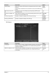
... and VIA to enable or disable the AMD Virtualization Technology (VT) function. Select OS/2 if the system is running OS/2 operating system and the system memory is only required for the password each time the system boots up. Specifies the version of the Multiprocessor Specification (MPS) that the mainboard will ask...
... and VIA to enable or disable the AMD Virtualization Technology (VT) function. Select OS/2 if the system is running OS/2 operating system and the system memory is only required for the password each time the system boots up. Specifies the version of the Multiprocessor Specification (MPS) that the mainboard will ask...
Aspire X1200 / X3200 Service Guide
Page 23
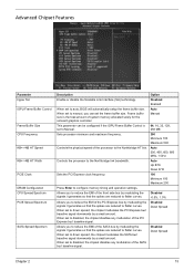
...any modulation of the SATA bus by a small amount. Disabled Enabled When set to disabled, the chipset disables any modulation of system memory allocated solely for the onboard graphics controller. Disabled -0.5%, 1.0% Allows you can be configured if the iGPU Frame Buffer Control is the ...physical speed of the processor to flatter curves. Auto 200, 400, 600, 800 MHz, 1 GHz Controls the processor to configure memory timing and operation settings. Advanced Chipset Features Parameter Hyper SLI iGPU Frame Buffer Control Frame Buffer Size CPU Frequency KBNB HT Speed KBNB...
...any modulation of the SATA bus by a small amount. Disabled Enabled When set to disabled, the chipset disables any modulation of system memory allocated solely for the onboard graphics controller. Disabled -0.5%, 1.0% Allows you can be configured if the iGPU Frame Buffer Control is the ...physical speed of the processor to flatter curves. Auto 200, 400, 600, 800 MHz, 1 GHz Controls the processor to configure memory timing and operation settings. Advanced Chipset Features Parameter Hyper SLI iGPU Frame Buffer Control Frame Buffer Size CPU Frequency KBNB HT Speed KBNB...
Aspire X1200 / X3200 Service Guide
Page 25
...and Alt VD Enabled Disabled Enabled Disabled Minimim 0000 Maximum 00FC Chapter 2 17 Allows you to auto optimize maximal memory size when kernel assigns PCI Resources. Option Auto MaxMemClk Disabled Enabled Per Channel Per CS Disabled Memclock tristating during...power state at which the memory retains data. Enables or disables memory remapping around the memory hole. All synchronous memory devices can manually specify the memory clock frequency independent of the memory modules and adjusts the timings accordingly. Displays the current memory clock frequency. Sets the CKE...
...and Alt VD Enabled Disabled Enabled Disabled Minimim 0000 Maximum 00FC Chapter 2 17 Allows you to auto optimize maximal memory size when kernel assigns PCI Resources. Option Auto MaxMemClk Disabled Enabled Per Channel Per CS Disabled Memclock tristating during...power state at which the memory retains data. Enables or disables memory remapping around the memory hole. All synchronous memory devices can manually specify the memory clock frequency independent of the memory modules and adjusts the timings accordingly. Displays the current memory clock frequency. Sets the CKE...
Aspire X1200 / X3200 Service Guide
Page 27
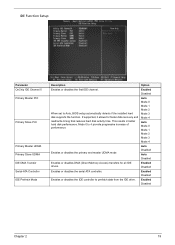
... 3 Mode 4 Auto Mode 0 Mode 1 Mode 2 Mode 3 Mode 4 Enables or disables the primary and master UDMA mode Auto Disabled Auto Disabled Enables or disables DMA (Direct Memory Access) transfers for faster data recovery and read/write timing that reduces hard disk activity time. This results in better hard disk performance. IDE Function...
... 3 Mode 4 Auto Mode 0 Mode 1 Mode 2 Mode 3 Mode 4 Enables or disables the primary and master UDMA mode Auto Disabled Auto Disabled Enables or disables DMA (Direct Memory Access) transfers for faster data recovery and read/write timing that reduces hard disk activity time. This results in better hard disk performance. IDE Function...
Aspire X1200 / X3200 Service Guide
Page 33
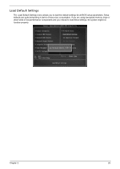
Setup defaults are using low-speed memory chips or other kinds of resources consumption. Load Default Settings The Load Default Settings menu allows you are quite demanding in terms of low-performance components and you choose to load the default settings for all BIOS setup parameters. If you to load these settings, the system might not function properly. Chapter 2 25
Setup defaults are using low-speed memory chips or other kinds of resources consumption. Load Default Settings The Load Default Settings menu allows you are quite demanding in terms of low-performance components and you choose to load the default settings for all BIOS setup parameters. If you to load these settings, the system might not function properly. Chapter 2 25
Aspire X1200 / X3200 Service Guide
Page 41
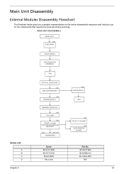
... SIDE PANEL FRONT BEZEL HEAT SINK FAN ASSEMBLY CPU OPTICAL DISK DRIVE Ax1 HDD-ODD BRACKET Ax4 POWER SUPPLY Bx1 HDD MODULE HDD Screw List A B C D MEMORY MODULES Ax1 PCI CARD Bx2 FRONT I/O AND CARD READER BOARD BRACKET Dx2 Ax6, Cx1 MAINBOARD Screw #6-32 L5 BZN #6-32*3/16 NI M3xL5 BZN Hex...
... SIDE PANEL FRONT BEZEL HEAT SINK FAN ASSEMBLY CPU OPTICAL DISK DRIVE Ax1 HDD-ODD BRACKET Ax4 POWER SUPPLY Bx1 HDD MODULE HDD Screw List A B C D MEMORY MODULES Ax1 PCI CARD Bx2 FRONT I/O AND CARD READER BOARD BRACKET Dx2 Ax6, Cx1 MAINBOARD Screw #6-32 L5 BZN #6-32*3/16 NI M3xL5 BZN Hex...
Aspire X1200 / X3200 Service Guide
Page 57
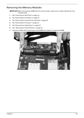
Removing the Memory Modules IMPORTANT:Before removing any DIMM from the memory board, make sure to create a backup file of the DIMM slot outward to release the DIMM. See "Removing the Processor" on page 34. 2. Press the holding clips on both sides of all important data. 1. Chapter 3 49 See "Removing the Side Panel" on page 38. 5. See "Removing the Heat Sink Fan Assembly" on page 42. 7. See "Removing the Hard Disk Drive" on page 36. 4. See "Removing the Optical Drive" on page 35. 3. See "Removing the Font Bezel" on page 40. 6.
Removing the Memory Modules IMPORTANT:Before removing any DIMM from the memory board, make sure to create a backup file of the DIMM slot outward to release the DIMM. See "Removing the Processor" on page 34. 2. Press the holding clips on both sides of all important data. 1. Chapter 3 49 See "Removing the Side Panel" on page 38. 5. See "Removing the Heat Sink Fan Assembly" on page 42. 7. See "Removing the Hard Disk Drive" on page 36. 4. See "Removing the Optical Drive" on page 35. 3. See "Removing the Font Bezel" on page 40. 6.
Aspire X1200 / X3200 Service Guide
Page 61
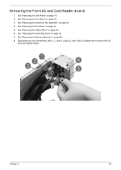
See "Removing the Processor" on page 36. 4. See "Removing the Heat Sink Fan Assembly" on page 38. 5. Disconnect one end of the three USB (1, 2, and 4), audio (2), and 1394 (5) cables from the rear of the I /O and Card Reader Boards 1. See "Removing the Optical Drive" on page 34. 2. See "Removing the Side Panel" on page 40. 6. See "Removing the Hard Disk Drive" on page 49. 8. See "Removing the Memory Modules" on page 42. 7. Removing the Front I /O and card reader boards. Chapter 3 53 See "Removing the Font Bezel" on page 35. 3.
See "Removing the Processor" on page 36. 4. See "Removing the Heat Sink Fan Assembly" on page 38. 5. Disconnect one end of the three USB (1, 2, and 4), audio (2), and 1394 (5) cables from the rear of the I /O and Card Reader Boards 1. See "Removing the Optical Drive" on page 34. 2. See "Removing the Side Panel" on page 40. 6. See "Removing the Hard Disk Drive" on page 49. 8. See "Removing the Memory Modules" on page 42. 7. Removing the Front I /O and card reader boards. Chapter 3 53 See "Removing the Font Bezel" on page 35. 3.
Aspire X1200 / X3200 Service Guide
Page 65
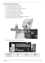
... N/A Part No. 86.1A324.5R0 N/A 57 Disconnect the LED cable from the rear panel. See "Removing the Optical Drive" on page 38. 5. See "Removing the Memory Modules" on page 34. 2. Removing the Mainboard 1. See "Removing the Side Panel" on page 49. 8. See "Removing the PCI Card" on page 51. 9. Remove the...
... N/A Part No. 86.1A324.5R0 N/A 57 Disconnect the LED cable from the rear panel. See "Removing the Optical Drive" on page 38. 5. See "Removing the Memory Modules" on page 34. 2. Removing the Mainboard 1. See "Removing the Side Panel" on page 49. 8. See "Removing the PCI Card" on page 51. 9. Remove the...
Aspire X1200 / X3200 Service Guide
Page 69
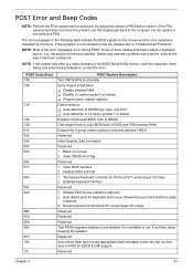
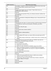
... 0Bh 0Ch 0Dh 0Eh 0Fh 10h 11h POST Routine Description Test CMOS R/W functionality Early chipset initialization T Disable shadow RAM T Disable L2 cache (socket 7 or below) T Program basic chipset registers Detect memory T Auto-detection of DRAM size, type, and ECC T Auto-detection of L2 cache (socket 7 or below...) Expand compressed BIOS code to DRAM Call chipset hook to copy BIOS back to E000 and F000 shadow RAM Expand the X group codes locating in ...
... 0Bh 0Ch 0Dh 0Eh 0Fh 10h 11h POST Routine Description Test CMOS R/W functionality Early chipset initialization T Disable shadow RAM T Disable L2 cache (socket 7 or below) T Program basic chipset registers Detect memory T Auto-detection of DRAM size, type, and ECC T Auto-detection of L2 cache (socket 7 or below...) Expand compressed BIOS code to DRAM Call chipset hook to copy BIOS back to E000 and F000 shadow RAM Expand the X group codes locating in ...
Aspire X1200 / X3200 Service Guide
Page 70
...ESCD is not defined Onboard clock generator initialization. a value of 5Ah is defined. Early PCI Initialization: T Enumerate PCI bus number T Assign memory & I/O resource T Search for Pentium class CPU. 3 Program early chipset according to SPURIOUS_soft_HDLR. Reserved Invoke Video BIOS Reserved 62 Chapter 4...Init onboard PWM 3 Init onboard H/W monitor devices Initialize INT 09 buffer Reserved 1 Program CPU internal MTRR (P6 & PII) for 0-640K memory address. 2 Initialize the APIC for a valid VGA device & VGA BIOS, and put it into BIOS stack. Reserved Initial onboard clock generator ...
...ESCD is not defined Onboard clock generator initialization. a value of 5Ah is defined. Early PCI Initialization: T Enumerate PCI bus number T Assign memory & I/O resource T Search for Pentium class CPU. 3 Program early chipset according to SPURIOUS_soft_HDLR. Reserved Invoke Video BIOS Reserved 62 Chapter 4...Init onboard PWM 3 Init onboard H/W monitor devices Initialize INT 09 buffer Reserved 1 Program CPU internal MTRR (P6 & PII) for 0-640K memory address. 2 Initialize the APIC for a valid VGA device & VGA BIOS, and put it into BIOS stack. Reserved Initial onboard clock generator ...
Aspire X1200 / X3200 Service Guide
Page 71
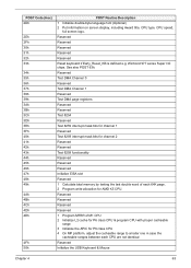
... bits for channel 1 Reserved Test 8259 interrupt mask bits for channel 2 Reserved Reserved Test 8259 functionality Reserved Reserved Reserved Initialize EISA slot Reserved 1 Calculate total memory by testing the last double word of M1 CPU 2 Initialize L2 cache for P6 class CPU & program CPU with proper cacheable range 3 Initialize the APIC...
... bits for channel 1 Reserved Test 8259 interrupt mask bits for channel 2 Reserved Reserved Test 8259 functionality Reserved Reserved Reserved Initialize EISA slot Reserved 1 Calculate total memory by testing the last double word of M1 CPU 2 Initialize L2 cache for P6 class CPU & program CPU with proper cacheable range 3 Initialize the APIC...
Aspire X1200 / X3200 Service Guide
Page 72
... ports to onboard COM ports if the corresponding item in Setup is not defined Reserved Initialize PS/2 Mouse Reserved Prepare memory size information for entering AWDFLASH.EXE from FDD Reserved 1 Initialize Init_Onboard_Super_IO 2 Initialize Init_Onbaord_AUDIO Reserved Reserved Okay to enter Setup... h 6 h 6h 67h 68h 69h 6Ah 6Bh 6Ch 6Dh 6Eh 6Fh 70h 71h 72h 73h 74h 75h POST Routine Description Reserved Test all memory (clear all extended memory to 0) Clear password according to H/W jumper (Optional) Reserved Display number of processors (multi-processor platform) Reserved 1 Display PnP logo 2 ...
... ports to onboard COM ports if the corresponding item in Setup is not defined Reserved Initialize PS/2 Mouse Reserved Prepare memory size information for entering AWDFLASH.EXE from FDD Reserved 1 Initialize Init_Onboard_Super_IO 2 Initialize Init_Onbaord_AUDIO Reserved Reserved Okay to enter Setup... h 6 h 6h 67h 68h 69h 6Ah 6Bh 6Ch 6Dh 6Eh 6Fh 70h 71h 72h 73h 74h 75h POST Routine Description Reserved Test all memory (clear all extended memory to 0) Clear password according to H/W jumper (Optional) Reserved Display number of processors (multi-processor platform) Reserved 1 Display PnP logo 2 ...
Aspire X1200 / X3200 Service Guide
Page 73
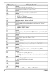
... screen back to text mode Reserved NET PC: Build SYSID Structure Reserved 1 Assign IRQs to PCI devices 2 Set up ACPI table at top of the memory Reserved 1 Invoke all ISA adapter ROMs 2 Invoke all data in floppy drive. -ALT+F2 is supported. Detect serial ports & parallel ports Reserved Reserved Detect & install...
... screen back to text mode Reserved NET PC: Build SYSID Structure Reserved 1 Assign IRQs to PCI devices 2 Set up ACPI table at top of the memory Reserved 1 Invoke all ISA adapter ROMs 2 Invoke all data in floppy drive. -ALT+F2 is supported. Detect serial ports & parallel ports Reserved Reserved Detect & install...
Aspire X1200 / X3200 Service Guide
Page 78
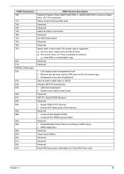
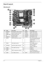
... Layout Mainboard No Code Description No Code 1 CPUFAN1 Processor fan cable connector 13 JBIOS1 2 PWR2 24-pin ATX power connector 14 FIREH1 3 DIMM1 and 2 System memory slots 15 AUDIOF1 4 UI Processor socket 16 PCIEX16 5 DEBUGH1 Debug connector 17 PCIEX1 6 SATA2 SATA 2 data cable connector 18 7 LEDH1 8 SYSFAN1 9 USBF3 10 USBF2 11...
... Layout Mainboard No Code Description No Code 1 CPUFAN1 Processor fan cable connector 13 JBIOS1 2 PWR2 24-pin ATX power connector 14 FIREH1 3 DIMM1 and 2 System memory slots 15 AUDIOF1 4 UI Processor socket 16 PCIEX16 5 DEBUGH1 Debug connector 17 PCIEX1 6 SATA2 SATA 2 data cable connector 18 7 LEDH1 8 SYSFAN1 9 USBF3 10 USBF2 11...


