Aspire X1200 / X3200 Service Guide
Page 7
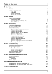
... the Front I/O and Card Reader Boards 53 Removing the Mainboard 57 System Troubleshooting 59 Hardware Diagnostic Procedure 59 System Check Procedures 60 Power System Check 60 System External Inspection 60 System Internal Inspection 60 POST Error and Beep Codes 61 Online Support Information 67 System Block ...Board Layout 69 System Block Diagram 69 Board Layout 70 Mainboard 70 System Jumpers 71 FRU (Field Replaceable Unit) List 73 Aspire ASX1200/ ASX3200 Exploded Diagram 74 Aspire ASX1200/ ASX3200 FRU List (81.3V001.010G) 75 Technical Specifications 83 vii
... the Front I/O and Card Reader Boards 53 Removing the Mainboard 57 System Troubleshooting 59 Hardware Diagnostic Procedure 59 System Check Procedures 60 Power System Check 60 System External Inspection 60 System Internal Inspection 60 POST Error and Beep Codes 61 Online Support Information 67 System Block ...Board Layout 69 System Block Diagram 69 Board Layout 70 Mainboard 70 System Jumpers 71 FRU (Field Replaceable Unit) List 73 Aspire ASX1200/ ASX3200 Exploded Diagram 74 Aspire ASX1200/ ASX3200 FRU List (81.3V001.010G) 75 Technical Specifications 83 vii
Aspire X1200 / X3200 Service Guide
Page 10
...-45) Operating system and software T Operating system options: t Genuine Windows Vista® Ultimate (32/64-bit) t Genuine Windows Vista Home Premium (32/64-bit) T Applications t Acer Empowering Technology (Acer eRecovery Management) t Acer Arcade Live t McAfee Internet Security Suite 2008 Trial version t Adobe Reader t eSobi t NTI MediaMaker...
...-45) Operating system and software T Operating system options: t Genuine Windows Vista® Ultimate (32/64-bit) t Genuine Windows Vista Home Premium (32/64-bit) T Applications t Acer Empowering Technology (Acer eRecovery Management) t Acer Arcade Live t McAfee Internet Security Suite 2008 Trial version t Adobe Reader t eSobi t NTI MediaMaker...
Aspire X1200 / X3200 Service Guide
Page 11
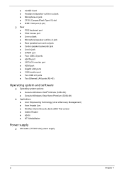
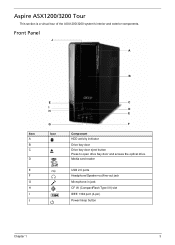
Media card reader USB 2.0 ports Headphone/Speaker-out/line-out jack Microphone-in jack CF I/II (CompactFlash Type I H G Icon C D E F Component HDD activity indicator Drive bay door Drive bay door eject button Press to open drive bay door and access the optical drive. Aspire ASX1200/3200 Tour This section is a virtual tour of the ASX1200/3200 system's interior and exterior components. Front Panel J A B Item A B C D E F G H I J E I /II) slot IEEE 1394 port (4-pin) Power/sleep button Chapter 1 3
Media card reader USB 2.0 ports Headphone/Speaker-out/line-out jack Microphone-in jack CF I/II (CompactFlash Type I H G Icon C D E F Component HDD activity indicator Drive bay door Drive bay door eject button Press to open drive bay door and access the optical drive. Aspire ASX1200/3200 Tour This section is a virtual tour of the ASX1200/3200 system's interior and exterior components. Front Panel J A B Item A B C D E F G H I J E I /II) slot IEEE 1394 port (4-pin) Power/sleep button Chapter 1 3
Aspire X1200 / X3200 Service Guide
Page 12
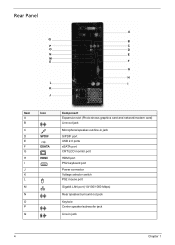
Rear Panel A Q B P C O D N E M E F G H L I K J Item A B C D E F G H I J K L M N O P Q Icon SPDIF ESATA HDMI Component Expansion slot (Photo shows graphics card and network/modem card) Line-out jack Microphone/speaker-out/line-in jack S/PDIF port USB 2.0 ports eSATA port CRT/LCD monitor port HDMI port PS2 keyboard port Power connector Voltage selector switch PS2 mouse port Gigabit LAN port (10/100/1000 Mbps) Rear speaker/surround out jack Keyhole Center speaker/subwoofer jack Line-in jack 4 Chapter 1
Rear Panel A Q B P C O D N E M E F G H L I K J Item A B C D E F G H I J K L M N O P Q Icon SPDIF ESATA HDMI Component Expansion slot (Photo shows graphics card and network/modem card) Line-out jack Microphone/speaker-out/line-in jack S/PDIF port USB 2.0 ports eSATA port CRT/LCD monitor port HDMI port PS2 keyboard port Power connector Voltage selector switch PS2 mouse port Gigabit LAN port (10/100/1000 Mbps) Rear speaker/surround out jack Keyhole Center speaker/subwoofer jack Line-in jack 4 Chapter 1
Aspire X1200 / X3200 Service Guide
Page 13
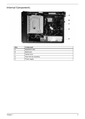
Internal Components A B C D E Item A B C D E Component Expansion card Mainboard Optical drive Heat sink fan assembly Power supply Chapter 1 5
Internal Components A B C D E Item A B C D E Component Expansion card Mainboard Optical drive Heat sink fan assembly Power supply Chapter 1 5
Aspire X1200 / X3200 Service Guide
Page 14
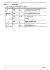
... data activity Off-line network 6 Chapter 1 The system is installed and functioning correctly. HDD is in standby mode. System is powered on . Green Green Green/ Amber Amber Amber Green - Green LED status On Blinking Off On Blinking Flashing Description The system has AC... power and is not powered on . System LED Indicators This section describes the different system LED indicators. LED indicator Power HDD activity LAN port network speed LED (left) LAN port network connection LED (right...
... data activity Off-line network 6 Chapter 1 The system is installed and functioning correctly. HDD is in standby mode. System is powered on . Green Green Green/ Amber Amber Amber Green - Green LED status On Blinking Off On Blinking Flashing Description The system has AC... power and is not powered on . System LED Indicators This section describes the different system LED indicators. LED indicator Power HDD activity LAN port network speed LED (left) LAN port network connection LED (right...
Aspire X1200 / X3200 Service Guide
Page 15
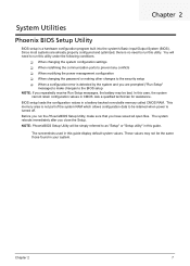
This memory area is not part of the system RAM which allows configuration data to the BIOS setup NOTE: If you repeatedly receive Run Setup messages, the battery may not be retained when power is a hardware configuration program built into the system's Basic Input/Output ...open files. The screenshots used in a battery-backed nonvolatile memory called CMOS RAM. T When changing the system configuration settings T When redefining the communication ports to prevent any conflicts T When modifying the power management configuration T When changing the password or making other changes to the ...
This memory area is not part of the system RAM which allows configuration data to the BIOS setup NOTE: If you repeatedly receive Run Setup messages, the battery may not be retained when power is a hardware configuration program built into the system's Basic Input/Output ...open files. The screenshots used in a battery-backed nonvolatile memory called CMOS RAM. T When changing the system configuration settings T When redefining the communication ports to prevent any conflicts T When modifying the power management configuration T When changing the password or making other changes to the ...
Aspire X1200 / X3200 Service Guide
Page 17
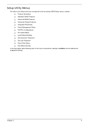
Setup Utility Menus The tabs on the Setup menu bar correspond to the six primary BIOS Setup menus, namely: T Product Information T Standard CMOS Features T Advanced BIOS Features T Advanced Chipset Features T Integrated Peripherals T Power Management Setup T PnP/PCI Configurations T PC Health Status T Load Default Settings T Set Supervisor Password T Set User Password T Save & Exit Setup T Exit Without Saving In the descriptive table following each of the menu screenshots, settings in boldface are the default and suggested settings. Chapter 2 9
Setup Utility Menus The tabs on the Setup menu bar correspond to the six primary BIOS Setup menus, namely: T Product Information T Standard CMOS Features T Advanced BIOS Features T Advanced Chipset Features T Integrated Peripherals T Power Management Setup T PnP/PCI Configurations T PC Health Status T Load Default Settings T Set Supervisor Password T Set User Password T Save & Exit Setup T Exit Without Saving In the descriptive table following each of the menu screenshots, settings in boldface are the default and suggested settings. Chapter 2 9
Aspire X1200 / X3200 Service Guide
Page 20
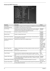
...Disk Boot Priority Press Enter to skip certain test while booting. Enabled Disabled External Cache Enables or disables internal cache. Enabled Disabled Quick Power On Self Test Allows the system to select hard disk boot device priority. Disabled Enabled CPU Internal Cache Enables or disables CPU internal... the time needed to configure the CPU Virtualization and AMD K8 Cool and Quiet Control features. Enabled Boot Up NumLock Status Selects power on the screen or an alarm beep when someone attempts to fast, the motherboard chipset controls the operation of Gate A20. This...
...Disk Boot Priority Press Enter to skip certain test while booting. Enabled Disabled External Cache Enables or disables internal cache. Enabled Disabled Quick Power On Self Test Allows the system to select hard disk boot device priority. Disabled Enabled CPU Internal Cache Enables or disables CPU internal... the time needed to configure the CPU Virtualization and AMD K8 Cool and Quiet Control features. Enabled Boot Up NumLock Status Selects power on the screen or an alarm beep when someone attempts to fast, the motherboard chipset controls the operation of Gate A20. This...
Aspire X1200 / X3200 Service Guide
Page 21
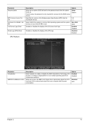
.... If set to auto, the AMD Cool'n'Quiet driver dynamically adjust the CPU clock and VIA to reduce heat output from your computer and its power consumption. Specifies the version of the Multiprocessor Specification (MPS) that the mainboard will ask for access into the BIOS setup menus. Enables or disables the...
.... If set to auto, the AMD Cool'n'Quiet driver dynamically adjust the CPU clock and VIA to reduce heat output from your computer and its power consumption. Specifies the version of the Multiprocessor Specification (MPS) that the mainboard will ask for access into the BIOS setup menus. Enables or disables the...
Aspire X1200 / X3200 Service Guide
Page 25
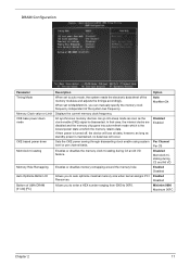
...or per channel basis. DRAM Configuration Parameter Timing Mode Memory Clock value or Limit CKE base power down mode CKE based power down Memclock tri-stating Memory Hole Remapping Auto Optimize Bottom IO Bottom of UMA DRAM [31...clocks are disabled and the memory chip goes into sleep mode as soon as standby power is maintained, no data loss will lose all data, however, as long as the clock enable (CKE...) signal is the lowest power state at which is disasserted. Displays the current memory clock frequency. Allows you to auto optimize...
...or per channel basis. DRAM Configuration Parameter Timing Mode Memory Clock value or Limit CKE base power down mode CKE based power down Memclock tri-stating Memory Hole Remapping Auto Optimize Bottom IO Bottom of UMA DRAM [31...clocks are disabled and the memory chip goes into sleep mode as soon as standby power is maintained, no data loss will lose all data, however, as long as the clock enable (CKE...) signal is the lowest power state at which is disasserted. Displays the current memory clock frequency. Allows you to auto optimize...
Aspire X1200 / X3200 Service Guide
Page 28
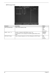
This parameter can be configured if the SATA Operation Mode is set to 6. Option AHCI IDE RAID Linux AHCI Disabled Enabled Off Partial Slumber 20 Chapter 2 Enables or disables the SATA RAID on ports 1 to RAID Select a Supports Aggressive Link Power Management (SALP) feature. Port 1 ~ 6 SATA SALP Feature Description Select a SATA operation mode. MCP Storage Config Parameter SATA Operation Mode SATA 0 --
This parameter can be configured if the SATA Operation Mode is set to 6. Option AHCI IDE RAID Linux AHCI Disabled Enabled Off Partial Slumber 20 Chapter 2 Enables or disables the SATA RAID on ports 1 to RAID Select a Supports Aggressive Link Power Management (SALP) feature. Port 1 ~ 6 SATA SALP Feature Description Select a SATA operation mode. MCP Storage Config Parameter SATA Operation Mode SATA 0 --
Aspire X1200 / X3200 Service Guide
Page 30
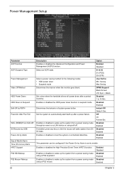
... function in Suspend Soft-Off by PBTN PowerOn After Pwr-Fail WOL (PME#)/From Soft-Off S5 Resume by USB Power-On by Alarm is set to wake up after a period inactivity. Option Enabled Disabled S1 & S3 S1 (POS) S3 (STR) User Define Min. Enables or ...disables to boot the system on a LAN device or using a PS2 mouse. Power Management Setup Parameter ACPI function ACPI Suspend Type Power Management Video Off Method HDD Power Down HDD Down in suspend mode. Select an ACPI state. Enables or disables to wake up the system from...
... function in Suspend Soft-Off by PBTN PowerOn After Pwr-Fail WOL (PME#)/From Soft-Off S5 Resume by USB Power-On by Alarm is set to wake up after a period inactivity. Option Enabled Disabled S1 & S3 S1 (POS) S3 (STR) User Define Min. Enables or ...disables to boot the system on a LAN device or using a PS2 mouse. Power Management Setup Parameter ACPI function ACPI Suspend Type Power Management Video Off Method HDD Power Down HDD Down in suspend mode. Select an ACPI state. Enables or disables to wake up the system from...

Aspire X1200 / X3200 Service Guide
Page 40
Turn off the system and all peripheral cables from the power outlets. 3. Pre-disassembly Procedure Before proceeding with the disassembly procedure, perform the steps listed below: 1. Place the system unit on a flat, stable surface. 32 Chapter 3 Unplug all the peripherals connected to it. 2. Unplug the power cord from the system. 5. Unplug the power cord from the system. 4.
Turn off the system and all peripheral cables from the power outlets. 3. Pre-disassembly Procedure Before proceeding with the disassembly procedure, perform the steps listed below: 1. Place the system unit on a flat, stable surface. 32 Chapter 3 Unplug all the peripherals connected to it. 2. Unplug the power cord from the system. 5. Unplug the power cord from the system. 4.
Aspire X1200 / X3200 Service Guide
Page 41
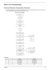
MAIN UNIT DISASSEMBLY MAIN UNIT Ax2 SIDE PANEL FRONT BEZEL HEAT SINK FAN ASSEMBLY CPU OPTICAL DISK DRIVE Ax1 HDD-ODD BRACKET Ax4 POWER SUPPLY Bx1 HDD MODULE HDD Screw List A B C D MEMORY MODULES Ax1 PCI CARD Bx2 FRONT I/O AND CARD READER BOARD BRACKET Dx2 Ax6, Cx1 MAINBOARD Screw #6-32 ...
MAIN UNIT DISASSEMBLY MAIN UNIT Ax2 SIDE PANEL FRONT BEZEL HEAT SINK FAN ASSEMBLY CPU OPTICAL DISK DRIVE Ax1 HDD-ODD BRACKET Ax4 POWER SUPPLY Bx1 HDD MODULE HDD Screw List A B C D MEMORY MODULES Ax1 PCI CARD Bx2 FRONT I/O AND CARD READER BOARD BRACKET Dx2 Ax6, Cx1 MAINBOARD Screw #6-32 ...
Aspire X1200 / X3200 Service Guide
Page 48
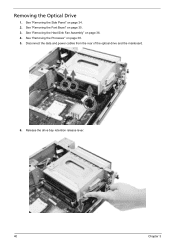
See "Removing the Side Panel" on page 36. 4. See "Removing the Heat Sink Fan Assembly" on page 34. 2. See "Removing the Processor" on page 35. 3. Release the drive bay retention release lever. 40 Chapter 3 Disconnect the data and power cables from the rear of the optical drive and the mainboard. 6. See "Removing the Font Bezel" on page 38. 5. Removing the Optical Drive 1.
See "Removing the Side Panel" on page 36. 4. See "Removing the Heat Sink Fan Assembly" on page 34. 2. See "Removing the Processor" on page 35. 3. Release the drive bay retention release lever. 40 Chapter 3 Disconnect the data and power cables from the rear of the optical drive and the mainboard. 6. See "Removing the Font Bezel" on page 38. 5. Removing the Optical Drive 1.
Aspire X1200 / X3200 Service Guide
Page 52
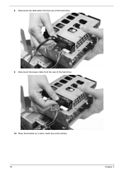
Place the bracket on a clean, static-free work surface. 44 Chapter 3 8. Disconnect the data cable from the rear of the hard drive. 9. Disconnect the power cable from the rear of the hard drive. 10.
Place the bracket on a clean, static-free work surface. 44 Chapter 3 8. Disconnect the data cable from the rear of the hard drive. 9. Disconnect the power cable from the rear of the hard drive. 10.
Aspire X1200 / X3200 Service Guide
Page 54
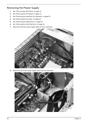
See "Removing the Font Bezel" on page 40. 6. Disconnect the 8-pin power supply cable from the mainboard. 46 Chapter 3 See "Removing the Optical Drive" on page 35. 3. Disconnect the 24-pin power supply cable from the mainboard. 8. See "Removing the Side Panel" on page 42. 7. See "Removing the Hard Disk Drive" on page 34. 2. See "Removing the Heat Sink Fan Assembly" on page 38. 5. See "Removing the Processor" on page 36. 4. Removing the Power Supply 1.
See "Removing the Font Bezel" on page 40. 6. Disconnect the 8-pin power supply cable from the mainboard. 46 Chapter 3 See "Removing the Optical Drive" on page 35. 3. Disconnect the 24-pin power supply cable from the mainboard. 8. See "Removing the Side Panel" on page 42. 7. See "Removing the Hard Disk Drive" on page 34. 2. See "Removing the Heat Sink Fan Assembly" on page 38. 5. See "Removing the Processor" on page 36. 4. Removing the Power Supply 1.
Aspire X1200 / X3200 Service Guide
Page 55
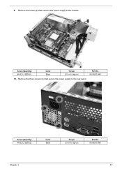
Remove the three screws (A) that secures the power supply to the rear panel. Screw (Quantity) #6-32 L5 BZN (3) Color Black Torque 5.5 to 6.5 kgf-cm Part No. 86.00J07.B60 10. Screw (Quantity) #6-32 L5 BZN (1) Color Black Torque 5.5 to 6.5 kgf-cm Part No. 86.00J07.B60 Chapter 3 47 9. Remove the screw (A) that secure the power supply to the chassis.
Remove the three screws (A) that secures the power supply to the rear panel. Screw (Quantity) #6-32 L5 BZN (3) Color Black Torque 5.5 to 6.5 kgf-cm Part No. 86.00J07.B60 10. Screw (Quantity) #6-32 L5 BZN (1) Color Black Torque 5.5 to 6.5 kgf-cm Part No. 86.00J07.B60 Chapter 3 47 9. Remove the screw (A) that secure the power supply to the chassis.
Aspire X1200 / X3200 Service Guide
Page 56
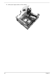
Lift the power supply module out of the chassis. 48 Chapter 3 11.
Lift the power supply module out of the chassis. 48 Chapter 3 11.


