Aspire X1200 / X3200 Service Guide
Page 6
... or the responsible personnel/channel to provide you with all technical information relating to the BASIC CONFIGURATION decided for Acer's "global" product offering. For ACER-AUTHORIZED SERVICE PROVIDERS, your regional web or channel. You MUST use the list provided by your regional office ... printed Service Guide. vi To better fit local market requirements and enhance product competitiveness, your regional Acer office to -date information available on card, modem, or extra memory capability). If, for repair and service of a machine (e.g. Service Guide Coverage This Service Guide ...
... or the responsible personnel/channel to provide you with all technical information relating to the BASIC CONFIGURATION decided for Acer's "global" product offering. For ACER-AUTHORIZED SERVICE PROVIDERS, your regional web or channel. You MUST use the list provided by your regional office ... printed Service Guide. vi To better fit local market requirements and enhance product competitiveness, your regional Acer office to -date information available on card, modem, or extra memory capability). If, for repair and service of a machine (e.g. Service Guide Coverage This Service Guide ...
Aspire X1200 / X3200 Service Guide
Page 7
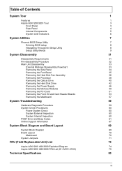
...Fan Assembly 36 Removing the Processor 38 Removing the Optical Drive 40 Removing the Hard Disk Drive 42 Removing the Power Supply 46 Removing the Memory Modules 49 Removing the PCI Card 51 Removing the Front I/O and Card Reader Boards 53 Removing the Mainboard 57 System Troubleshooting 59 Hardware ...Diagram and Board Layout 69 System Block Diagram 69 Board Layout 70 Mainboard 70 System Jumpers 71 FRU (Field Replaceable Unit) List 73 Aspire ASX1200/ ASX3200 Exploded Diagram 74 Aspire ASX1200/ ASX3200 FRU List (81.3V001.010G) 75 Technical Specifications 83 vii
...Fan Assembly 36 Removing the Processor 38 Removing the Optical Drive 40 Removing the Hard Disk Drive 42 Removing the Power Supply 46 Removing the Memory Modules 49 Removing the PCI Card 51 Removing the Front I/O and Card Reader Boards 53 Removing the Mainboard 57 System Troubleshooting 59 Hardware ...Diagram and Board Layout 69 System Block Diagram 69 Board Layout 70 Mainboard 70 System Jumpers 71 FRU (Field Replaceable Unit) List 73 Aspire ASX1200/ ASX3200 Exploded Diagram 74 Aspire ASX1200/ ASX3200 FRU List (81.3V001.010G) 75 Technical Specifications 83 vii
Aspire X1200 / X3200 Service Guide
Page 9
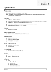
... processor T AMD Phenom X4 Quad-Core 9100e/9150e/9500/9550/9600/9650 processor T AMD Sempron LE-1250/1300 or 2100 processor Chipset T NVIDIA nForce MCP78 Memory subsystem T Supports up to two DDR2-667 registered ECC modules Media storage T DVD-ROM SATA drive T Super-Multi SATA DVD drive T 160... GB SATA hard disk drive Serial ATA controller T Embedded SATA2 controller T Two SATA ports Networking T One Gigabit Ethernet LAN port (RJ-45) PCI I/O T One PCI Express ...
... processor T AMD Phenom X4 Quad-Core 9100e/9150e/9500/9550/9600/9650 processor T AMD Sempron LE-1250/1300 or 2100 processor Chipset T NVIDIA nForce MCP78 Memory subsystem T Supports up to two DDR2-667 registered ECC modules Media storage T DVD-ROM SATA drive T Super-Multi SATA DVD drive T 160... GB SATA hard disk drive Serial ATA controller T Embedded SATA2 controller T Two SATA ports Networking T One Gigabit Ethernet LAN port (RJ-45) PCI I/O T One PCI Express ...
Aspire X1200 / X3200 Service Guide
Page 15
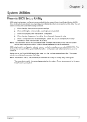
Since most systems are prompted ("Run Setup" message) to make sure that you have saved all open files. In this guide. This memory area is not part of the system RAM which allows configuration data to be retained when power is no need to run the PhoenixBIOS Setup Utility, make changes to as... optimized, there is turned off. BIOS setup loads the configuration values in this utility under the following conditions. The screenshots used in a battery-backed nonvolatile memory called CMOS RAM.
Since most systems are prompted ("Run Setup" message) to make sure that you have saved all open files. In this guide. This memory area is not part of the system RAM which allows configuration data to be retained when power is no need to run the PhoenixBIOS Setup Utility, make changes to as... optimized, there is turned off. BIOS setup loads the configuration values in this utility under the following conditions. The screenshots used in a battery-backed nonvolatile memory called CMOS RAM.
Aspire X1200 / X3200 Service Guide
Page 19
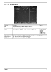
...CMOS Features Parameter Date Time Halt On Base Memory Extended Memory Total Memory Description Option Set the date following the hour-minute-second format. All, But Keyboard No Errors All Errors All, But Diskette All, But Disk/Key Also called conventional memory. Typically, 640 KB will stop for the... MS-DOS OS. Total size of extended memory detected during POST Total size of system memory detected during the POST. Determines whether the system will be reserved for...
...CMOS Features Parameter Date Time Halt On Base Memory Extended Memory Total Memory Description Option Set the date following the hour-minute-second format. All, But Keyboard No Errors All Errors All, But Diskette All, But Disk/Key Also called conventional memory. Typically, 640 KB will stop for the... MS-DOS OS. Total size of extended memory detected during POST Total size of system memory detected during the POST. Determines whether the system will be reserved for...
Aspire X1200 / X3200 Service Guide
Page 21
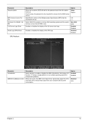
Select OS/2 if the system is running OS/2 operating system and the system memory is only required for the password each time the system boots up. Option Setup System 1.4 1.1 Non-OS/2 OS/2 Enabled Disabled Disabled Enabled CPU Feature Parameter ...
Select OS/2 if the system is running OS/2 operating system and the system memory is only required for the password each time the system boots up. Option Setup System 1.4 1.1 Non-OS/2 OS/2 Enabled Disabled Disabled Enabled CPU Feature Parameter ...
Aspire X1200 / X3200 Service Guide
Page 23
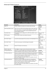
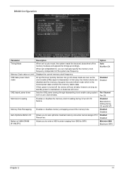
...PCI Express bus' baseline signal downwards by modulating the signals it generates so that the spikes are reduced to flatter curves. When set to configure memory timing and operation settings. Allows you to reduce the EMI of the front side bus by a small amount. When set to flatter curves.... is 64, 16, 32, 128, set to the Northbridge HT link. When set to disabled, the chipset disables any modulation of system memory allocated solely for the onboard graphics controller. Disabled Enabled When set to auto, BIOS will automatically setup the frame buffer size.
...PCI Express bus' baseline signal downwards by modulating the signals it generates so that the spikes are reduced to flatter curves. When set to configure memory timing and operation settings. Allows you to reduce the EMI of the front side bus by a small amount. When set to flatter curves.... is 64, 16, 32, 128, set to the Northbridge HT link. When set to disabled, the chipset disables any modulation of system memory allocated solely for the onboard graphics controller. Disabled Enabled When set to auto, BIOS will automatically setup the frame buffer size.
Aspire X1200 / X3200 Service Guide
Page 25
...all data, however, as long as the clock enable (CKE) signal is disasserted. Displays the current memory clock frequency. All synchronous memory devices can manually specify the memory clock frequency independent of the system bus frequency. When set to auto mode, the system reads the electronic... Disabled Enabled Per Channel Per CS Disabled Memclock tristating during C3 an Alt VD feature. Enables or disables memory remapping around the memory hole. DRAM Configuration Parameter Timing Mode Memory Clock value or Limit CKE base power down mode CKE based power down Memclock tri-stating...
...all data, however, as long as the clock enable (CKE) signal is disasserted. Displays the current memory clock frequency. All synchronous memory devices can manually specify the memory clock frequency independent of the system bus frequency. When set to auto mode, the system reads the electronic... Disabled Enabled Per Channel Per CS Disabled Memclock tristating during C3 an Alt VD feature. Enables or disables memory remapping around the memory hole. DRAM Configuration Parameter Timing Mode Memory Clock value or Limit CKE base power down mode CKE based power down Memclock tri-stating...
Aspire X1200 / X3200 Service Guide
Page 27
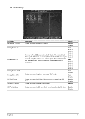
... 3 Mode 4 Auto Mode 0 Mode 1 Mode 2 Mode 3 Mode 4 Enables or disables the primary and master UDMA mode Auto Disabled Auto Disabled Enables or disables DMA (Direct Memory Access) transfers for faster data recovery and read/write timing that reduces hard disk activity time. Enabled Disabled Enables or disables the IDE controller to...
... 3 Mode 4 Auto Mode 0 Mode 1 Mode 2 Mode 3 Mode 4 Enables or disables the primary and master UDMA mode Auto Disabled Auto Disabled Enables or disables DMA (Direct Memory Access) transfers for faster data recovery and read/write timing that reduces hard disk activity time. Enabled Disabled Enables or disables the IDE controller to...
Aspire X1200 / X3200 Service Guide
Page 33
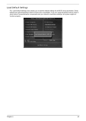
Setup defaults are using low-speed memory chips or other kinds of resources consumption. If you are quite demanding in terms of low-performance components and you to load these settings, the system might not function properly. Chapter 2 25 Load Default Settings The Load Default Settings menu allows you choose to load the default settings for all BIOS setup parameters.
Setup defaults are using low-speed memory chips or other kinds of resources consumption. If you are quite demanding in terms of low-performance components and you to load these settings, the system might not function properly. Chapter 2 25 Load Default Settings The Load Default Settings menu allows you choose to load the default settings for all BIOS setup parameters.
Aspire X1200 / X3200 Service Guide
Page 41
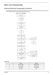
... SIDE PANEL FRONT BEZEL HEAT SINK FAN ASSEMBLY CPU OPTICAL DISK DRIVE Ax1 HDD-ODD BRACKET Ax4 POWER SUPPLY Bx1 HDD MODULE HDD Screw List A B C D MEMORY MODULES Ax1 PCI CARD Bx2 FRONT I/O AND CARD READER BOARD BRACKET Dx2 Ax6, Cx1 MAINBOARD Screw #6-32 L5 BZN #6-32*3/16 NI M3xL5 BZN Hex...
... SIDE PANEL FRONT BEZEL HEAT SINK FAN ASSEMBLY CPU OPTICAL DISK DRIVE Ax1 HDD-ODD BRACKET Ax4 POWER SUPPLY Bx1 HDD MODULE HDD Screw List A B C D MEMORY MODULES Ax1 PCI CARD Bx2 FRONT I/O AND CARD READER BOARD BRACKET Dx2 Ax6, Cx1 MAINBOARD Screw #6-32 L5 BZN #6-32*3/16 NI M3xL5 BZN Hex...
Aspire X1200 / X3200 Service Guide
Page 57
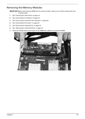
See "Removing the Heat Sink Fan Assembly" on page 38. 5. See "Removing the Processor" on page 36. 4. See "Removing the Font Bezel" on page 42. 7. See "Removing the Hard Disk Drive" on page 35. 3. Removing the Memory Modules IMPORTANT:Before removing any DIMM from the memory board, make sure to create a backup file of the DIMM slot outward to release the DIMM. Chapter 3 49 See "Removing the Optical Drive" on both sides of all important data. 1. Press the holding clips on page 40. 6. See "Removing the Side Panel" on page 34. 2.
See "Removing the Heat Sink Fan Assembly" on page 38. 5. See "Removing the Processor" on page 36. 4. See "Removing the Font Bezel" on page 42. 7. See "Removing the Hard Disk Drive" on page 35. 3. Removing the Memory Modules IMPORTANT:Before removing any DIMM from the memory board, make sure to create a backup file of the DIMM slot outward to release the DIMM. Chapter 3 49 See "Removing the Optical Drive" on both sides of all important data. 1. Press the holding clips on page 40. 6. See "Removing the Side Panel" on page 34. 2.
Aspire X1200 / X3200 Service Guide
Page 61
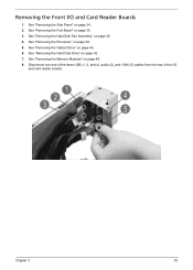
See "Removing the Hard Disk Drive" on page 35. 3. See "Removing the Font Bezel" on page 42. 7. Disconnect one end of the three USB (1, 2, and 4), audio (2), and 1394 (5) cables from the rear of the I /O and Card Reader Boards 1. See "Removing the Heat Sink Fan Assembly" on page 38. 5. Removing the Front I /O and card reader boards. See "Removing the Processor" on page 36. 4. See "Removing the Optical Drive" on page 49. 8. Chapter 3 53 See "Removing the Memory Modules" on page 40. 6. See "Removing the Side Panel" on page 34. 2.
See "Removing the Hard Disk Drive" on page 35. 3. See "Removing the Font Bezel" on page 42. 7. Disconnect one end of the three USB (1, 2, and 4), audio (2), and 1394 (5) cables from the rear of the I /O and Card Reader Boards 1. See "Removing the Heat Sink Fan Assembly" on page 38. 5. Removing the Front I /O and card reader boards. See "Removing the Processor" on page 36. 4. See "Removing the Optical Drive" on page 49. 8. Chapter 3 53 See "Removing the Memory Modules" on page 40. 6. See "Removing the Side Panel" on page 34. 2.
Aspire X1200 / X3200 Service Guide
Page 65
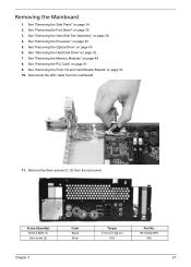
... 53. 10. Screw (Quantity) M3xL5 BZN (1) Hex screw (2) Chapter 3 Color Black Silver Torque 5.5 to 6.5 kgf-cm N/A Part No. 86.1A324.5R0 N/A 57 See "Removing the Memory Modules" on page 36. 4. Remove the three screws (C, D) from the mainboard. 11. Removing the Mainboard 1. See "Removing the Heat Sink Fan Assembly" on page 49...
... 53. 10. Screw (Quantity) M3xL5 BZN (1) Hex screw (2) Chapter 3 Color Black Silver Torque 5.5 to 6.5 kgf-cm N/A Part No. 86.1A324.5R0 N/A 57 See "Removing the Memory Modules" on page 36. 4. Remove the three screws (C, D) from the mainboard. 11. Removing the Mainboard 1. See "Removing the Heat Sink Fan Assembly" on page 49...
Aspire X1200 / X3200 Service Guide
Page 69
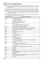
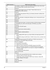
... 0Bh 0Ch 0Dh 0Eh 0Fh 10h 11h POST Routine Description Test CMOS R/W functionality Early chipset initialization T Disable shadow RAM T Disable L2 cache (socket 7 or below) T Program basic chipset registers Detect memory T Auto-detection of DRAM size, type, and ECC T Auto-detection of L2 cache (socket 7 or below...) Expand compressed BIOS code to DRAM Call chipset hook to copy BIOS back to E000 and F000 shadow RAM Expand the X group codes locating in ...
... 0Bh 0Ch 0Dh 0Eh 0Fh 10h 11h POST Routine Description Test CMOS R/W functionality Early chipset initialization T Disable shadow RAM T Disable L2 cache (socket 7 or below) T Program basic chipset registers Detect memory T Auto-detection of DRAM size, type, and ECC T Auto-detection of L2 cache (socket 7 or below...) Expand compressed BIOS code to DRAM Call chipset hook to copy BIOS back to E000 and F000 shadow RAM Expand the X group codes locating in ...
Aspire X1200 / X3200 Service Guide
Page 70
... & DIMM slots. 2 Init onboard PWM 3 Init onboard H/W monitor devices Initialize INT 09 buffer Reserved 1 Program CPU internal MTRR (P6 & PII) for 0-640K memory address. 2 Initialize the APIC for Pentium class CPU. 3 Program early chipset according to check out interface in CMOS circuitry. Measure CPU speed. POST Code (Hex... matrix (notebook platform) Reserved HPM initialization (notebook platform) Reserved 1 Check validity of RTC value: e.g. Early PCI Initialization: T Enumerate PCI bus number T Assign memory & I/O resource T Search for override. Example: onboard IDE controller.
... & DIMM slots. 2 Init onboard PWM 3 Init onboard H/W monitor devices Initialize INT 09 buffer Reserved 1 Program CPU internal MTRR (P6 & PII) for 0-640K memory address. 2 Initialize the APIC for Pentium class CPU. 3 Program early chipset according to check out interface in CMOS circuitry. Measure CPU speed. POST Code (Hex... matrix (notebook platform) Reserved HPM initialization (notebook platform) Reserved 1 Check validity of RTC value: e.g. Early PCI Initialization: T Enumerate PCI bus number T Assign memory & I/O resource T Search for override. Example: onboard IDE controller.
Aspire X1200 / X3200 Service Guide
Page 71
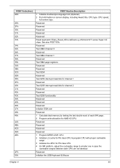
... bits for channel 1 Reserved Test 8259 interrupt mask bits for channel 2 Reserved Reserved Test 8259 functionality Reserved Reserved Reserved Initialize EISA slot Reserved 1 Calculate total memory by testing the last double word of M1 CPU 2 Initialize L2 cache for P6 class CPU & program CPU with proper cacheable range 3 Initialize the APIC...
... bits for channel 1 Reserved Test 8259 interrupt mask bits for channel 2 Reserved Reserved Test 8259 functionality Reserved Reserved Reserved Initialize EISA slot Reserved 1 Calculate total memory by testing the last double word of M1 CPU 2 Initialize L2 cache for P6 class CPU & program CPU with proper cacheable range 3 Initialize the APIC...
Aspire X1200 / X3200 Service Guide
Page 72
... 6 h 6h 67h 68h 69h 6Ah 6Bh 6Ch 6Dh 6Eh 6Fh 70h 71h 72h 73h 74h 75h POST Routine Description Reserved Test all memory (clear all extended memory to 0) Clear password according to H/W jumper (Optional) Reserved Display number of processors (multi-processor platform) Reserved 1 Display PnP logo ...Reserved Program chipset registers according to items described in Setup is not defined Reserved Initialize PS/2 Mouse Reserved Prepare memory size information for entering AWDFLASH.EXE from FDD Reserved 1 Initialize Init_Onboard_Super_IO 2 Initialize Init_Onbaord_AUDIO Reserved Reserved Okay to enter...
... 6 h 6h 67h 68h 69h 6Ah 6Bh 6Ch 6Dh 6Eh 6Fh 70h 71h 72h 73h 74h 75h POST Routine Description Reserved Test all memory (clear all extended memory to 0) Clear password according to H/W jumper (Optional) Reserved Display number of processors (multi-processor platform) Reserved 1 Display PnP logo ...Reserved Program chipset registers according to items described in Setup is not defined Reserved Initialize PS/2 Mouse Reserved Prepare memory size information for entering AWDFLASH.EXE from FDD Reserved 1 Initialize Init_Onboard_Super_IO 2 Initialize Init_Onbaord_AUDIO Reserved Reserved Okay to enter...
Aspire X1200 / X3200 Service Guide
Page 73
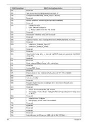
... Reserved Reserved Detect & install co-processor Reserved Init HDD write protect Reserved Reserved Switch back to CMOS setup 2 APM Initialization Reserved Clear noise of the memory Reserved 1 Invoke all ISA adapter ROMs 2 Invoke all data in floppy drive. -ALT+F2 is pressed. POST Code (Hex) 76h 77h 78h 79h 7Ah 7Bh...
... Reserved Reserved Detect & install co-processor Reserved Init HDD write protect Reserved Reserved Switch back to CMOS setup 2 APM Initialization Reserved Clear noise of the memory Reserved 1 Invoke all ISA adapter ROMs 2 Invoke all data in floppy drive. -ALT+F2 is pressed. POST Code (Hex) 76h 77h 78h 79h 7Ah 7Bh...
Aspire X1200 / X3200 Service Guide
Page 78
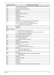
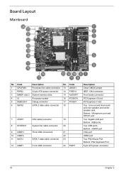
... Layout Mainboard No Code Description No Code 1 CPUFAN1 Processor fan cable connector 13 JBIOS1 2 PWR2 24-pin ATX power connector 14 FIREH1 3 DIMM1 and 2 System memory slots 15 AUDIOF1 4 UI Processor socket 16 PCIEX16 5 DEBUGH1 Debug connector 17 PCIEX1 6 SATA2 SATA 2 data cable connector 18 7 LEDH1 8 SYSFAN1 9 USBF3 10 USBF2 11...
... Layout Mainboard No Code Description No Code 1 CPUFAN1 Processor fan cable connector 13 JBIOS1 2 PWR2 24-pin ATX power connector 14 FIREH1 3 DIMM1 and 2 System memory slots 15 AUDIOF1 4 UI Processor socket 16 PCIEX16 5 DEBUGH1 Debug connector 17 PCIEX1 6 SATA2 SATA 2 data cable connector 18 7 LEDH1 8 SYSFAN1 9 USBF3 10 USBF2 11...


