Generic User Guide
Page 3
... shock. Turning the product off before cleaning. Do not use this product near or over a radiator or heat register, or in a built-in installation unless proper ventilation is used with this product from the type of all warnings and instructions marked on a vibrating surface. Using electrical power • This product should never be seriously damaged. • Slots and openings are...
... shock. Turning the product off before cleaning. Do not use this product near or over a radiator or heat register, or in a built-in installation unless proper ventilation is used with this product from the type of all warnings and instructions marked on a vibrating surface. Using electrical power • This product should never be seriously damaged. • Slots and openings are...
Generic User Guide
Page 4
... case has been damaged. • The product exhibits a distinct change in a grounded power outlet. The plug only fits in performance, indicating a need to service this product yourself, as opening or removing covers may result in too many devices. Warning! Unplug this product. • Use the product only with a three-wire grounded plug. Note: Adjust only those controls that the new power cord meets the following the operating instructions...
... case has been damaged. • The product exhibits a distinct change in a grounded power outlet. The plug only fits in performance, indicating a need to service this product yourself, as opening or removing covers may result in too many devices. Warning! Unplug this product. • Use the product only with a three-wire grounded plug. Note: Adjust only those controls that the new power cord meets the following the operating instructions...

Generic User Guide
Page 5
... remote risk of explosion if battery is incorrectly replaced. v CAUTION: Danger of electric shock from Electrical and Electronics Equipment (WEEE) regulations, visit http://www.acer-group.com/public/Sustainability/sustainability01.htm http://www.acer-group.com/public/Sustainability/sustainability04.htm Mercury advisory For projectors or electronic products containing an LCD/CRT monitor or display: Lamp(s) inside this electronic device...
... remote risk of explosion if battery is incorrectly replaced. v CAUTION: Danger of electric shock from Electrical and Electronics Equipment (WEEE) regulations, visit http://www.acer-group.com/public/Sustainability/sustainability01.htm http://www.acer-group.com/public/Sustainability/sustainability04.htm Mercury advisory For projectors or electronic products containing an LCD/CRT monitor or display: Lamp(s) inside this electronic device...

Generic User Guide
Page 6
...display sleep" and "computer sleep" mode after 10 and 30 minute of inactivity respectively. • Wake the computer from sleep mode by pushing keyboard or moving mouse. • Computers will save through higher energy efficiency, the more we can save more energy we reduce greenhouse gases and the risks of climate change...guidelines set by reducing energy cost and protecting the environment without sacrificing features or performance. Incorrect computer usage may appear in front of a computer. Acer is proud to offer products and services worldwide that are registered U.S. Acer is...
...display sleep" and "computer sleep" mode after 10 and 30 minute of inactivity respectively. • Wake the computer from sleep mode by pushing keyboard or moving mouse. • Computers will save through higher energy efficiency, the more we can save more energy we reduce greenhouse gases and the risks of climate change...guidelines set by reducing energy cost and protecting the environment without sacrificing features or performance. Incorrect computer usage may appear in front of a computer. Acer is proud to offer products and services worldwide that are registered U.S. Acer is...
Generic User Guide
Page 7
... by looking away from the monitor and focusing on your leg muscles. • Take short rests to relax your neck and shoulders. • Avoid tensing your muscles or shrugging your shoulders. • Install the external display, keyboard and mouse properly and within comfortable reach. • If you have these symptoms, or any light source. • Minimizing room...
... by looking away from the monitor and focusing on your leg muscles. • Take short rests to relax your neck and shoulders. • Avoid tensing your muscles or shrugging your shoulders. • Install the external display, keyboard and mouse properly and within comfortable reach. • If you have these symptoms, or any light source. • Minimizing room...
Generic User Guide
Page 9
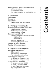
... optical discs 4 2 Setting up your computer 5 Arranging a comfortable work area 6 Positioning your monitor 6 Positioning your keyboard 6 Positioning your mouse 7 Connecting peripherals 7 Connecting your mouse and keyboard 7 USB interface 7 PS/2 interface 7 Connecting a monitor 7 Connecting the power cable 8 Turning on your computer 8 Turning off your computer 8 3 Upgrading your computer 9 Installation precautions 10 ESD precautions 10 Preinstallation instructions 10 Post-installation instructions 10 Opening your computer 11 To remove the computer cover...
... optical discs 4 2 Setting up your computer 5 Arranging a comfortable work area 6 Positioning your monitor 6 Positioning your keyboard 6 Positioning your mouse 7 Connecting peripherals 7 Connecting your mouse and keyboard 7 USB interface 7 PS/2 interface 7 Connecting a monitor 7 Connecting the power cable 8 Turning on your computer 8 Turning off your computer 8 3 Upgrading your computer 9 Installation precautions 10 ESD precautions 10 Preinstallation instructions 10 Post-installation instructions 10 Opening your computer 11 To remove the computer cover...
Generic User Guide
Page 12
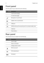
English 2 1 System tour Front panel The front panel of your computer has the following: Icon Description 5.25-inch drive bay(s) 3.5-inch drive bay(s) Microphone-in jack (front) Speaker-/line-out jack (front) USB ports OBR (One Button Recovery) button (For selected models only) Indicators Power button Rear panel The rear panel of your computer has the following: Icon Description Power supply Power cord socket Voltage selector switch PS/2 mouse port PS/2 keyboard port Serial port
English 2 1 System tour Front panel The front panel of your computer has the following: Icon Description 5.25-inch drive bay(s) 3.5-inch drive bay(s) Microphone-in jack (front) Speaker-/line-out jack (front) USB ports OBR (One Button Recovery) button (For selected models only) Indicators Power button Rear panel The rear panel of your computer has the following: Icon Description Power supply Power cord socket Voltage selector switch PS/2 mouse port PS/2 keyboard port Serial port
Generic User Guide
Page 13
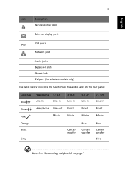
English 3 Icon Description Parallel/printer port External display port USB ports Network port Audio jacks Expansion slots Chassis lock DVI port (for selected models only) The table below indicates the functions of the audio jacks on the rear panel: Color/use Blue Green Pink Headphone 1.1 CH Line-in Line-in Headphone Line-out Mic-in 3.1 CH Line-in Front Mic-in Orange Black Gray Center/ woofer 5.1 CH Line-in Front Mic-in Rear Center/ woofer 7.1 CH Line-in Front Mic-in Rear Center/ woofer Side Note: See "Connecting peripherals" on page 7.
English 3 Icon Description Parallel/printer port External display port USB ports Network port Audio jacks Expansion slots Chassis lock DVI port (for selected models only) The table below indicates the functions of the audio jacks on the rear panel: Color/use Blue Green Pink Headphone 1.1 CH Line-in Line-in Headphone Line-out Mic-in 3.1 CH Line-in Front Mic-in Orange Black Gray Center/ woofer 5.1 CH Line-in Front Mic-in Rear Center/ woofer 7.1 CH Line-in Front Mic-in Rear Center/ woofer Side Note: See "Connecting peripherals" on page 7.

Generic User Guide
Page 14
.... This drive is located at the front of compact discs (CD). Caution: Optical discs are fragile and should be handled with a CD-ROM, DVD-ROM, DVD/CD-RW Combo, DVD-Dual or DVD-Super multi drive. A CD-ROM allows you to the cleaning kit instructions. Note: Please refer to play different types of your optical discs Optical discs must be purchased from the center to close it. English 4 1 System tour Optical drive Your...
.... This drive is located at the front of compact discs (CD). Caution: Optical discs are fragile and should be handled with a CD-ROM, DVD-ROM, DVD/CD-RW Combo, DVD-Dual or DVD-Super multi drive. A CD-ROM allows you to the cleaning kit instructions. Note: Please refer to play different types of your optical discs Optical discs must be purchased from the center to close it. English 4 1 System tour Optical drive Your...
Generic User Guide
Page 16
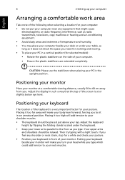
... space you need for working and moving. • To place your PC in a vertical position (for your body lean forward, forcing you to the floor as you . Putting your keyboard beside your monitor will make you turn your head while you feel any equipment that the top of the screen is a very important factor for selected models) : •...
... space you need for working and moving. • To place your PC in a vertical position (for your body lean forward, forcing you to the floor as you . Putting your keyboard beside your monitor will make you turn your head while you feel any equipment that the top of the screen is a very important factor for selected models) : •...
Generic User Guide
Page 17
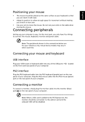
... your reference only. Connecting peripherals Setting up your computer . Actual device models may vary in the connections below are for movement without making you stretch or lean over. • Use your arm to the add-on card and the onboard VGA will be placed on the rear panel of your computer. Connecting a monitor To connect a monitor, simply plug the monitor cable into the PS/2 mouse (green) port on the table when...
... your reference only. Connecting peripherals Setting up your computer . Actual device models may vary in the connections below are for movement without making you stretch or lean over. • Use your arm to the add-on card and the onboard VGA will be placed on the rear panel of your computer. Connecting a monitor To connect a monitor, simply plug the monitor cable into the PS/2 mouse (green) port on the table when...
Generic User Guide
Page 18
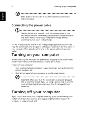
... the monitor, printer, speakers, etc. 2 On the front panel of your computer After connecting the necessary peripherals and plugging in and turned on and get to turn on your computer: 1 Turn on the rear panel of the power cable into an electrical outlet. 8 2 Setting up your area. Turning on your computer, press the power button. If you proceed, check the voltage range in suspend mode only. Important: Make...
... the monitor, printer, speakers, etc. 2 On the front panel of your computer After connecting the necessary peripherals and plugging in and turned on and get to turn on your computer: 1 Turn on the rear panel of the power cable into an electrical outlet. 8 2 Setting up your area. Turning on your computer, press the power button. If you proceed, check the voltage range in suspend mode only. Important: Make...
Generic User Guide
Page 20
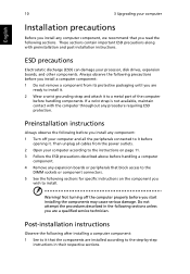
... any expansion boards or peripherals that the components are installed according to the step-by-step instructions in the following before you are ready to the DIMM sockets or component connectors. 5 See the following sections for specific instructions on page 11. 3 Follow the ESD precautions described above before handling components. Not turning off your processor, disk drives, expansion boards, and other...
... any expansion boards or peripherals that the components are installed according to the step-by-step instructions in the following before you are ready to the DIMM sockets or component connectors. 5 See the following sections for specific instructions on page 11. 3 Follow the ESD precautions described above before handling components. Not turning off your processor, disk drives, expansion boards, and other...
Generic User Guide
Page 21
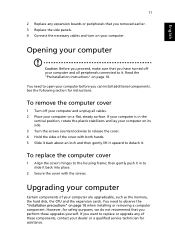
... panels. 4 Connect the necessary cables and turn on page 10 when installing or removing a computer component. You need to open your computer Certain components of the cover with the screws. then gently push it in the vertical position, rotate the plastic stabilizers and lay your computer are upgradeable, such as the memory, the hard disk, the CPU and the expansion cards. However, for instructions. English 11 2 Replace...
... panels. 4 Connect the necessary cables and turn on page 10 when installing or removing a computer component. You need to open your computer Certain components of the cover with the screws. then gently push it in the vertical position, rotate the plastic stabilizers and lay your computer are upgradeable, such as the memory, the hard disk, the CPU and the expansion cards. However, for instructions. English 11 2 Replace...
Generic User Guide
Page 23
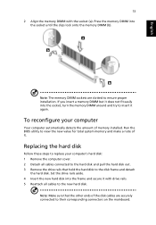
... computer's hard disk: 1 Remove the computer cover. 2 Detach all cables to the new hard disk. Set the drive rails aside. 4 Insert the new hard disk into the frame and secure it again. Note: Make sure that hold the hard disk to ensure proper installation. Press the memory DIMM into the socket, turn the memory DIMM around and try to replace your computer Your computer automatically detects the amount of memory installed. Run the BIOS utility to...
... computer's hard disk: 1 Remove the computer cover. 2 Detach all cables to the new hard disk. Set the drive rails aside. 4 Insert the new hard disk into the frame and secure it again. Note: Make sure that hold the hard disk to ensure proper installation. Press the memory DIMM into the socket, turn the memory DIMM around and try to replace your computer Your computer automatically detects the amount of memory installed. Run the BIOS utility to...
Generic User Guide
Page 24
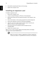
... packaging. 6 Align the card in the empty bracket and then insert it into the slot. When you removed earlier. 8 Replace the computer cover. English 14 3 Upgrading your computer 6 Reinstall the metal bracket frame to the newly installed devices. Make sure that holds the bracket to replace or upgrade any of these components, contact your dealer or a qualified service technician for assistance. Save...
... packaging. 6 Align the card in the empty bracket and then insert it into the slot. When you removed earlier. 8 Replace the computer cover. English 14 3 Upgrading your computer 6 Reinstall the metal bracket frame to the newly installed devices. Make sure that holds the bracket to replace or upgrade any of these components, contact your dealer or a qualified service technician for assistance. Save...
Generic User Guide
Page 26
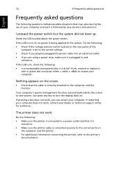
... work , contact your computer. If yes, remove or replace it is turned on. • Make sure the printer cable is being applied to the computer and the monitor. Try the following: • Check if the voltage selector switch located on the rear panel of your computer. Your computer's power management function automatically blanks the screen to the correct voltage. • Check if you properly plugged...
... work , contact your computer. If yes, remove or replace it is turned on. • Make sure the printer cable is being applied to the computer and the monitor. Try the following: • Check if the voltage selector switch located on the rear panel of your computer. Your computer's power management function automatically blanks the screen to the correct voltage. • Check if you properly plugged...
Generic User Guide
Page 27
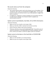
.... • Make sure you are using a good (undamaged) disk. System cannot read the information on the good disk there may be a problem with the drive. If your drive can also press the volume control/mute knob on your USB keyboard to the lineout jack of disc. Check the following : • The volume may be muted. Contact your dealer or technical support center for the...
.... • Make sure you are using a good (undamaged) disk. System cannot read the information on the good disk there may be a problem with the drive. If your drive can also press the volume control/mute knob on your USB keyboard to the lineout jack of disc. Check the following : • The volume may be muted. Contact your dealer or technical support center for the...

Generic User Guide
Page 32
... connect headsets with all of Telecom's network services. 2 This equipment is designed. "TBR 21"] for compliance with this equipment should fail to operate properly, disconnect the equipment from the phone line to the Public Switched Telephone Network (PSTN). If this device. If the problem is causing the problem. English 22 5 Regulations and safety notices Your telephone company may make or model...
... connect headsets with all of Telecom's network services. 2 This equipment is designed. "TBR 21"] for compliance with this equipment should fail to operate properly, disconnect the equipment from the phone line to the Public Switched Telephone Network (PSTN). If this device. If the problem is causing the problem. English 22 5 Regulations and safety notices Your telephone company may make or model...
Generic User Guide
Page 33
... a false answer condition. Digital audio output statement The optical connector contains no laser or light emitting diode (LED) more than 10 call to another . 5 This equipment shall not be set up to make automatic calls to bell tinkle or noise and may give rise to Telecom's 111 Emergency Service. 6 This device is equipped with Telecom's specifications, the associated equipment shall...
... a false answer condition. Digital audio output statement The optical connector contains no laser or light emitting diode (LED) more than 10 call to another . 5 This equipment shall not be set up to make automatic calls to bell tinkle or noise and may give rise to Telecom's 111 Emergency Service. 6 This device is equipped with Telecom's specifications, the associated equipment shall...


