
User Guide
Page 3
... locate this product through cabinet slots as they may touch dangerous voltage points or short-out parts that the total ampere rating of all warnings and instructions marked on the power cord. Keep this product from the type of power available, consult your safety and comfort Safety instructions Read these instructions carefully. The openings should be seriously damaged. • Slots and openings...
... locate this product through cabinet slots as they may touch dangerous voltage points or short-out parts that the total ampere rating of all warnings and instructions marked on the power cord. Keep this product from the type of power available, consult your safety and comfort Safety instructions Read these instructions carefully. The openings should be seriously damaged. • Slots and openings...
User Guide
Page 4
... water • the product has been dropped or the case has been damaged • the product exhibits a distinct change in performance, indicating a need to qualified service personnel. Warning! iv circuit rating. Refer all servicing to replace the power cord set, make sure that the new power cord meets the following the operating instructions Note: Adjust only those controls that is equipped with the supplied power supply cord set.
... water • the product has been dropped or the case has been damaged • the product exhibits a distinct change in performance, indicating a need to qualified service personnel. Warning! iv circuit rating. Refer all servicing to replace the power cord set, make sure that the new power cord meets the following the operating instructions Note: Adjust only those controls that is equipped with the supplied power supply cord set.
User Guide
Page 5
... pollution and ensure utmost protection of used batteries according to the manufacturer's instructions. For lamp-specific disposal information, check www.lamprecycle.org. Telephone line safety • Disconnect all telephone lines from the equipment when not in use and/or before servicing. • To avoid the remote risk of explosion if battery is incorrectly replaced. For more information, contact the...
... pollution and ensure utmost protection of used batteries according to the manufacturer's instructions. For lamp-specific disposal information, check www.lamprecycle.org. Telephone line safety • Disconnect all telephone lines from the equipment when not in use and/or before servicing. • To avoid the remote risk of explosion if battery is incorrectly replaced. For more information, contact the...
User Guide
Page 6
... efficiency guidelines set by pushing power button. • More power management settings can be done through Acer ePower Management. Incorrect computer usage may complain of eyestrain and headaches after long hours of physical injury. Tips and information for power management: • Activate display' Sleep mode within 15 minutes of user inactivity. • Activate computer's Sleep mode within 30 minutes of user inactivity. • Wake the computer from Sleep mode by...
... efficiency guidelines set by pushing power button. • More power management settings can be done through Acer ePower Management. Incorrect computer usage may complain of eyestrain and headaches after long hours of physical injury. Tips and information for power management: • Activate display' Sleep mode within 15 minutes of user inactivity. • Activate computer's Sleep mode within 30 minutes of user inactivity. • Wake the computer from Sleep mode by...

User Guide
Page 7
... shoulders • install the external display, keyboard and mouse properly and within ...use . Finding your comfort zone Find your comfort zone by adjusting the viewing angle of your vision Long viewing hours, wearing incorrect glasses or contact lenses, glare, excessive room lighting, poorly focused screens, very small typefaces and low-contrast displays...monitor more comfortable computer use , consult a physician immediately and inform your company's health and safety department. Observe the following section provides tips for more than your documents, place the display at the center...
... shoulders • install the external display, keyboard and mouse properly and within ...use . Finding your comfort zone Find your comfort zone by adjusting the viewing angle of your vision Long viewing hours, wearing incorrect glasses or contact lenses, glare, excessive room lighting, poorly focused screens, very small typefaces and low-contrast displays...monitor more comfortable computer use , consult a physician immediately and inform your company's health and safety department. Observe the following section provides tips for more than your documents, place the display at the center...
User Guide
Page 9
... 7 Connecting your mouse and keyboard 7 USB interface 7 PS/2 interface 7 Connecting a monitor 7 Connecting the power cable 8 Turning on your computer 8 Turning off your computer 8 3 Upgrading your computer 9 Installation precautions 10 ESD precautions 10 Preinstallation instructions 10 Post-installation instructions 11 Opening your computer 11 To remove the computer cover 11 To replace the computer cover 11 Upgrading your computer 11 To remove a memory DIMM 12 To install a memory DIMM 12 To reconfigure your computer 13 Replacing the hard disk 13
... 7 Connecting your mouse and keyboard 7 USB interface 7 PS/2 interface 7 Connecting a monitor 7 Connecting the power cable 8 Turning on your computer 8 Turning off your computer 8 3 Upgrading your computer 9 Installation precautions 10 ESD precautions 10 Preinstallation instructions 10 Post-installation instructions 11 Opening your computer 11 To remove the computer cover 11 To replace the computer cover 11 Upgrading your computer 11 To remove a memory DIMM 12 To install a memory DIMM 12 To reconfigure your computer 13 Replacing the hard disk 13

User Guide
Page 12
... panel Your computer's front panel consists of the following: Icon Component 5.25" drive bay(s) 3.5" floppy drive Microphone-in jack (front) Speaker-out/line-out port USB ports OBR (One Button Recovery) button (for selected models) Indicators Power button Rear panel Your computer's rear panel consists of the following: Icon Component Power supply Power cord socket Voltage selector switch PS/2 mouse port PS/2 keyboard port Serial port Parallel/printer port CRT/LCD monitor port USB ports Network port Audio jack Expansion slots Chassis lock pad DVI port (for selected models...
... panel Your computer's front panel consists of the following: Icon Component 5.25" drive bay(s) 3.5" floppy drive Microphone-in jack (front) Speaker-out/line-out port USB ports OBR (One Button Recovery) button (for selected models) Indicators Power button Rear panel Your computer's rear panel consists of the following: Icon Component Power supply Power cord socket Voltage selector switch PS/2 mouse port PS/2 keyboard port Serial port Parallel/printer port CRT/LCD monitor port USB ports Network port Audio jack Expansion slots Chassis lock pad DVI port (for selected models...

User Guide
Page 13
... you to carry around. When the disk tray slides open, place the CD or DVD gently on page 7 Optical drive Your computer may come with a CD-ROM, DVD-ROM, DVD/CD-RW combo, DVD-Dual or DVD-Super multi drive. Make sure that the label or title side of the disk is a type of disk media with extra care. Taking care of your computer. However, they are also...
... you to carry around. When the disk tray slides open, place the CD or DVD gently on page 7 Optical drive Your computer may come with a CD-ROM, DVD-ROM, DVD/CD-RW combo, DVD-Dual or DVD-Super multi drive. Make sure that the label or title side of the disk is a type of disk media with extra care. Taking care of your computer. However, they are also...
User Guide
Page 16
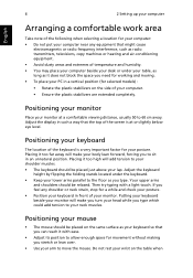
... the floor as your keyboard so that you can reach it with a light touch. Placing it too far away will make you turn your head while you stretch or lean over. • Use your arm to 60 cm away. Placing it too high will make your body lean forward, forcing you need for working and moving. • To...
... the floor as your keyboard so that you can reach it with a light touch. Placing it too far away will make you turn your head while you stretch or lean over. • Use your arm to 60 cm away. Placing it too high will make your body lean forward, forcing you need for working and moving. • To...

User Guide
Page 17
...added to the PCI Express slot, the monitor should be disabled. Connecting your mouse and keyboard USB interface Plug your USB mouse or keyboard cable into any of the USB ports on the rear panel of your reference only. located PS/2 interface Plug the PS/2 mouse and keyboard cable into the monitor port (blue port) located on card and the onboard VGA will be connected to connect: the mouse, the keyboard, the monitor, and the power cable. Connecting a monitor To connect a monitor, simply plug the monitor cable into the PS/2 keyboard port (purple port) and mouse port (green port) located...
...added to the PCI Express slot, the monitor should be disabled. Connecting your mouse and keyboard USB interface Plug your USB mouse or keyboard cable into any of the USB ports on the rear panel of your reference only. located PS/2 interface Plug the PS/2 mouse and keyboard cable into the monitor port (blue port) located on card and the onboard VGA will be connected to connect: the mouse, the keyboard, the monitor, and the power cable. Connecting a monitor To connect a monitor, simply plug the monitor cable into the PS/2 keyboard port (purple port) and mouse port (green port) located...
User Guide
Page 18
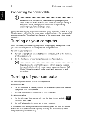
... suspend mode only. If they don't match, change your computer's voltage setting according to your area (a). Make sure that the power cable is plugged in and turned on the rear panel of the power cable into an electrical outlet. Set the voltage selector switch to the voltage range applicable to your area's voltage range. To turn off all peripherals connected to work. 8 2 Setting up your computer Connecting the power cable English...
... suspend mode only. If they don't match, change your computer's voltage setting according to your area (a). Make sure that the power cable is plugged in and turned on the rear panel of the power cable into an electrical outlet. Set the voltage selector switch to the voltage range applicable to your area's voltage range. To turn off all peripherals connected to work. 8 2 Setting up your computer Connecting the power cable English...
User Guide
Page 20
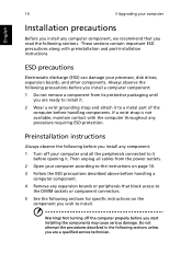
... you are a qualified service technician. English 10 3 Upgrading your computer Installation precautions Before you install any computer component, we recommend that block access to the DIMM sockets or component connectors. 5 See the following sections for specific instructions on the component you read the following precautions before you install a computer component: 1 Do not remove a component from the power outlets. 2 Open your computer according...
... you are a qualified service technician. English 10 3 Upgrading your computer Installation precautions Before you install any computer component, we recommend that block access to the DIMM sockets or component connectors. 5 See the following sections for specific instructions on the component you read the following precautions before you install a computer component: 1 Do not remove a component from the power outlets. 2 Open your computer according...

User Guide
Page 21
... stands and place your computer and unplug all peripherals connected to release the cover. 4 Hold the sides of the cover with the screws. English 11 Post-installation instructions Observe the following section for instructions. by-step instructions in to open your computer before you removed earlier. 3 Replace the side panels. 4 Connect the necessary cables and turn on your computer. then gently push it in...
... stands and place your computer and unplug all peripherals connected to release the cover. 4 Hold the sides of the cover with the screws. English 11 Post-installation instructions Observe the following section for instructions. by-step instructions in to open your computer before you removed earlier. 3 Replace the side panels. 4 Connect the necessary cables and turn on your computer. then gently push it in...
User Guide
Page 22
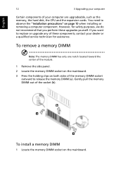
... only one notch located toward the center of the module. 1 Remove the side panel. 2 Locate the memory DIMM socket on the mainboard. 3 Press the holding clips on both sides of the memory DIMM socket outward to replace or upgrade any of these upgrades yourself. To install a memory DIMM 1 Locate the memory DIMM socket on page 10 when installing or removing a computer component. You need to observe the...
... only one notch located toward the center of the module. 1 Remove the side panel. 2 Locate the memory DIMM socket on the mainboard. 3 Press the holding clips on both sides of the memory DIMM socket outward to replace or upgrade any of these upgrades yourself. To install a memory DIMM 1 Locate the memory DIMM socket on page 10 when installing or removing a computer component. You need to observe the...
User Guide
Page 23
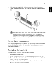
... memory DIMM with drive rails. 5 Reattach all cables connected to the hard disk and pull the hard disk out. 3 Remove the drive rails that hold the hard disk to the disk frame and detach the hard disk. Set the drive rails aside. 4 Insert the new hard disk into the frame and secure it with the socket (a). Run the BIOS utility to view the new value for total system memory and make a note of memory installed. If you insert a memory...
... memory DIMM with drive rails. 5 Reattach all cables connected to the hard disk and pull the hard disk out. 3 Remove the drive rails that hold the hard disk to the disk frame and detach the hard disk. Set the drive rails aside. 4 Insert the new hard disk into the frame and secure it with the socket (a). Run the BIOS utility to view the new value for total system memory and make a note of memory installed. If you insert a memory...
User Guide
Page 24
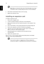
... Note: Make sure that the card is properly seated. 7 Secure the card to your dealer or a qualified service technician for assistance. Installing an expansion card To install an expansion card: 1 Remove the computer cover. 2 Locate an empty PCI Express or PCI slot on the computer, BIOS automatically detects and assigns resources to the newly installed devices. If you want to replace or upgrade any of the disk cables are securely connected to...
... Note: Make sure that the card is properly seated. 7 Secure the card to your dealer or a qualified service technician for assistance. Installing an expansion card To install an expansion card: 1 Remove the computer cover. 2 Locate an empty PCI Express or PCI slot on the computer, BIOS automatically detects and assigns resources to the newly installed devices. If you want to replace or upgrade any of the disk cables are securely connected to...
User Guide
Page 26
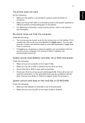
... yes, remove or replace it is plugged in the floppy drive? If restarting your computer does not work , you are using a power strip, make sure it with a system diskette and press + + to save power. Try the following : • Is a nonbootable (nonsystem) diskette in and turned on the rear panel of your dealer or technical support center for assistance. Your computer's power management function automatically blanks the screen to...
... yes, remove or replace it is plugged in the floppy drive? If restarting your computer does not work , you are using a power strip, make sure it with a system diskette and press + + to save power. Try the following : • Is a nonbootable (nonsystem) diskette in and turned on the rear panel of your dealer or technical support center for assistance. Your computer's power management function automatically blanks the screen to...
User Guide
Page 27
... your drive by using the correct type of disk. • Make sure the CD or DVD is inserted into the drive correctly. • Check if the CD or DVD is clean and unscratched. • Check your USB keyboard to a power outlet and that it is connected securely to the system's parallel or USB port and the corresponding port on . • If headphones, earphones or external speakers are connected...
... your drive by using the correct type of disk. • Make sure the CD or DVD is inserted into the drive correctly. • Check if the CD or DVD is clean and unscratched. • Check your USB keyboard to a power outlet and that it is connected securely to the system's parallel or USB port and the corresponding port on . • If headphones, earphones or external speakers are connected...

User Guide
Page 32
... Australia For safety reasons, only connect headsets with this However, due to the Public Switched Telephone Network (PSTN). Notice for compliance with minimum conditions for which it provide any sort of problems, you should difficulties arise in the country of fire, use only No. 26 AWG or larger UL Listed or CSA Certified Telecommunication Line Cord...
... Australia For safety reasons, only connect headsets with this However, due to the Public Switched Telephone Network (PSTN). Notice for compliance with minimum conditions for which it provide any sort of problems, you should difficulties arise in the country of fire, use only No. 26 AWG or larger UL Listed or CSA Certified Telecommunication Line Cord...
User Guide
Page 33
... limits for compliance with Telecom's Specifications: a There shall be set to ensure that automatic calls to Telecom's 111 Emergency Service. 6 This device is equipped with Telecom's specifications, the associated equipment shall be set to bell tinkle or noise and may not operate. AVOID EXPOSURE TO BEAM. Laser compliance statement The CD or DVD drive used with this equipment is a laser...
... limits for compliance with Telecom's Specifications: a There shall be set to ensure that automatic calls to Telecom's 111 Emergency Service. 6 This device is equipped with Telecom's specifications, the associated equipment shall be set to bell tinkle or noise and may not operate. AVOID EXPOSURE TO BEAM. Laser compliance statement The CD or DVD drive used with this equipment is a laser...


