
Veriton X461x Desktop Series Service Guide
Page 7
... Utilities 13 CMOS Setup Utility 13 Entering CMOS setup 14 Navigating Through the Setup Utility 14 Main 15 System Disassembly and Assembly 27 Disassembly Requirements 27 Pre-disassembly Procedure 28 Removing the Side Panel 29 Removing the Front Bezel 30 Removing the Heat Sink Fan Assembly 31 Removing the Processor 33 Removing the Wireless LAN Card 35 Removing the VGA Card 36 Removing the Memory Modules 37 Removing the Optical Drive 38 Removing the Hard Disk Drive 39 Removing the COM Port Cable and Printer Port Cable 42 Removing the Power Supply 44 Removing...
... Utilities 13 CMOS Setup Utility 13 Entering CMOS setup 14 Navigating Through the Setup Utility 14 Main 15 System Disassembly and Assembly 27 Disassembly Requirements 27 Pre-disassembly Procedure 28 Removing the Side Panel 29 Removing the Front Bezel 30 Removing the Heat Sink Fan Assembly 31 Removing the Processor 33 Removing the Wireless LAN Card 35 Removing the VGA Card 36 Removing the Memory Modules 37 Removing the Optical Drive 38 Removing the Hard Disk Drive 39 Removing the COM Port Cable and Printer Port Cable 42 Removing the Power Supply 44 Removing...
Veriton X461x Desktop Series Service Guide
Page 8
Install the Front Bezel 77 Install the Side Panel 78 System Troubleshooting 79 Hardware Diagnostic Procedure 79 System Check Procedures 80 Power System Check 80 System External Inspection 80 System Internal Inspection 80 Beep Codes 81 Checkpoints 82 BIOS Recovery 85 Jumper and Connector Information 86 M/B Placement 86 Jumper Setting 88 Setting Jumper 88 FRU (Field Replaceable Unit) List 96 Veriton X4610/X4610G/X4618G Exploded Diagram 97 Veriton X4610/X4610G/X4618G FRU List 98 viii
Install the Front Bezel 77 Install the Side Panel 78 System Troubleshooting 79 Hardware Diagnostic Procedure 79 System Check Procedures 80 Power System Check 80 System External Inspection 80 System Internal Inspection 80 Beep Codes 81 Checkpoints 82 BIOS Recovery 85 Jumper and Connector Information 86 M/B Placement 86 Jumper Setting 88 Setting Jumper 88 FRU (Field Replaceable Unit) List 96 Veriton X4610/X4610G/X4618G Exploded Diagram 97 Veriton X4610/X4610G/X4618G FRU List 98 viii
Veriton X461x Desktop Series Service Guide
Page 10
... Clear Video technology support • 1 D-sub VGA port on rear • 1 DVI-D port at rear side • Dual View function support • Need to 16GB Max memory support(using 4Gb tech). • DDR3 1.5V 1066/1333. • Design Criteria: • Should meet Intel Sandy Bridge Family design guide. • Support 1.5V DIMM. • Dual channel should be enabled always when plug-in the single PCIe X16 slot. Serial ATA controller • Slot Type: SATA connector • Slot...
... Clear Video technology support • 1 D-sub VGA port on rear • 1 DVI-D port at rear side • Dual View function support • Need to 16GB Max memory support(using 4Gb tech). • DDR3 1.5V 1066/1333. • Design Criteria: • Should meet Intel Sandy Bridge Family design guide. • Support 1.5V DIMM. • Dual channel should be enabled always when plug-in the single PCIe X16 slot. Serial ATA controller • Slot Type: SATA connector • Slot...
Veriton X461x Desktop Series Service Guide
Page 11
... color coding: should meet Microsoft Windows Logo Program Device Requirements: Audio-0002. • 1 front panel audio header (2*5). • 1 internal speaker header (2*4). • S/N ration: 90dB at rear output jack. • 1 front panel audio header (2*5). • Follow Acer Audio spec v4.1 & audio C/R should support Acer Internal speaker spec. • BIOS should meet MS Pin Configuration Guidelines for front daughter board. • 4 ports reserved. • Connector Pin: standard Intel FPIO pin definition. • Data transfer rate support: • USB 2.0/1.1 (3.0 by BOM option...
... color coding: should meet Microsoft Windows Logo Program Device Requirements: Audio-0002. • 1 front panel audio header (2*5). • 1 internal speaker header (2*4). • S/N ration: 90dB at rear output jack. • 1 front panel audio header (2*5). • Follow Acer Audio spec v4.1 & audio C/R should support Acer Internal speaker spec. • BIOS should meet MS Pin Configuration Guidelines for front daughter board. • 4 ports reserved. • Connector Pin: standard Intel FPIO pin definition. • Data transfer rate support: • USB 2.0/1.1 (3.0 by BOM option...
Veriton X461x Desktop Series Service Guide
Page 12
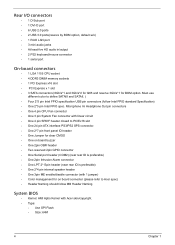
... keyboard/mouse connector • 1 serial port On-board connectors • 1 LGA 1155 CPU socket • 4 DDR3 DIMM memory sockets • 1 PCI Express x16 slot • PCI Express x 1 slot • 3 SATA connectors( 6Gb/s*1 and 3Gb/s*2 for Q65 and reserve 3Gb/s*1 for on board connecter (please refer to define SATAIII and SATAII. ) • Four 2*5 pin Intel FPIO specification USB pin connectors (follow MB Header Naming System BIOS • Kernel: AMI Aptio Kernel with 1 jumper) • Color management...
... keyboard/mouse connector • 1 serial port On-board connectors • 1 LGA 1155 CPU socket • 4 DDR3 DIMM memory sockets • 1 PCI Express x16 slot • PCI Express x 1 slot • 3 SATA connectors( 6Gb/s*1 and 3Gb/s*2 for Q65 and reserve 3Gb/s*1 for on board connecter (please refer to define SATAIII and SATAII. ) • Four 2*5 pin Intel FPIO specification USB pin connectors (follow MB Header Naming System BIOS • Kernel: AMI Aptio Kernel with 1 jumper) • Color management...
Veriton X461x Desktop Series Service Guide
Page 17
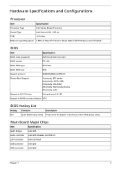
Hardware Specifications and Configurations Processor Item Specification Processor Type Intel Sandy Bridge Processor Socket Type Intel Socket LGA 1155 pin FSB 1333 MHz Minimum operating speed 0 MHz (If Stop CPU Clock in Sleep State in BIOS Setup is set to Enabled.) BIOS Item Specification BIOS code programer AMI Kernel with Acer skin BIOS version P01-A0 BIOS ROM type SPI Flash BIOS ROM size 8Mb Support protocol SMBIOS(DMI)2.4/DMI2.0 Device Boot Support 1st priority: EFI device 2nd priority: SATA HDD 3rd priority: CD-ROM 4th priority: Removable Device 5th priority...
Hardware Specifications and Configurations Processor Item Specification Processor Type Intel Sandy Bridge Processor Socket Type Intel Socket LGA 1155 pin FSB 1333 MHz Minimum operating speed 0 MHz (If Stop CPU Clock in Sleep State in BIOS Setup is set to Enabled.) BIOS Item Specification BIOS code programer AMI Kernel with Acer skin BIOS version P01-A0 BIOS ROM type SPI Flash BIOS ROM size 8Mb Support protocol SMBIOS(DMI)2.4/DMI2.0 Device Boot Support 1st priority: EFI device 2nd priority: SATA HDD 3rd priority: CD-ROM 4th priority: Removable Device 5th priority...
Veriton X461x Desktop Series Service Guide
Page 18
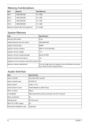
... feature Yes Support to error correction code (ECC) feature No Memory module combinations You can install memory modules in any combination as long as they match the above specifications. Audio Interface Item Audio controller Audio controller type Audio channel Audio function control Mono or stereo Compatibility Music synthesizer Sampling rate MPU-401 UART support Microphone/Headphone jack Specification Intel Q65 HDA controller ALC662-VC codec 5.1CH Enable/disable by BIOS Setup Stereo High...
... feature Yes Support to error correction code (ECC) feature No Memory module combinations You can install memory modules in any combination as long as they match the above specifications. Audio Interface Item Audio controller Audio controller type Audio channel Audio function control Mono or stereo Compatibility Music synthesizer Sampling rate MPU-401 UART support Microphone/Headphone jack Specification Intel Q65 HDA controller ALC662-VC codec 5.1CH Enable/disable by BIOS Setup Stereo High...
Veriton X461x Desktop Series Service Guide
Page 19
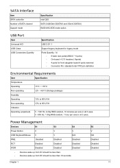
Chapter 1 S5 V N/A Disabled Disabled Disabled 11 SATA Interface Item SATA controller Number of SATA channel Support mode Specification Intel Q65 SATA X4(6Gb/s*2SATAIII and 3Gb/s*2SATAII) RAID/AHCI/IDE mode option USB Port Item Universal HCI USB Class USB Connectors Quantity Specification USB 2.0/1.1 Support legacy keyboard for legacy mode Ports Quantity: 14 • 6 back rear ports(USB2.0 * 6 ports) • On-board: 4 2*5 headers ( 8ports) • 4 ports for front daughter board,4 ports reserved • Connector Pin: standard Intel FPIO pin definition Environmental Requirements Item...
Chapter 1 S5 V N/A Disabled Disabled Disabled 11 SATA Interface Item SATA controller Number of SATA channel Support mode Specification Intel Q65 SATA X4(6Gb/s*2SATAIII and 3Gb/s*2SATAII) RAID/AHCI/IDE mode option USB Port Item Universal HCI USB Class USB Connectors Quantity Specification USB 2.0/1.1 Support legacy keyboard for legacy mode Ports Quantity: 14 • 6 back rear ports(USB2.0 * 6 ports) • On-board: 4 2*5 headers ( 8ports) • 4 ports for front daughter board,4 ports reserved • Connector Pin: standard Intel FPIO pin definition Environmental Requirements Item...
Veriton X461x Desktop Series Service Guide
Page 21
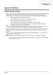
... Utilities CMOS Setup Utility CMOS setup is turned off. NOTE: CMOS Setup Utility will need to the CMOS setup NOTE: If you repeatedly receive Run Setup messages, the battery may not be simply referred to as "BIOS", "Setup", or "Setup utility" in this utility under the following conditions. • When changing the system configuration settings • When redefining the communication ports to prevent any conflicts • When modifying the power management configuration • When changing the password or making other changes to...
... Utilities CMOS Setup Utility CMOS setup is turned off. NOTE: CMOS Setup Utility will need to the CMOS setup NOTE: If you repeatedly receive Run Setup messages, the battery may not be simply referred to as "BIOS", "Setup", or "Setup utility" in this utility under the following conditions. • When changing the system configuration settings • When redefining the communication ports to prevent any conflicts • When modifying the power management configuration • When changing the password or making other changes to...
Veriton X461x Desktop Series Service Guide
Page 23
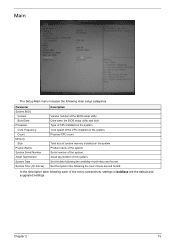
... built Type of the BIOS setup utility. Product name of system memory installed on the system. Set the system time following main setup categories. Physical CPU count Total size of the system. Asset tag number of the CPU installed on the system. Chapter 2 15 Core speed of this system. Set the date following each of the system. Serial number of the menu screenshots, settings in boldface are the default...
... built Type of the BIOS setup utility. Product name of system memory installed on the system. Set the system time following main setup categories. Physical CPU count Total size of the system. Asset tag number of the CPU installed on the system. Chapter 2 15 Core speed of this system. Set the date following each of the system. Serial number of the menu screenshots, settings in boldface are the default...

Veriton X461x Desktop Series Service Guide
Page 27
... Onboard SATA Mode Onboard USB Controller Legacy USB Support USB Storage Emulation Onboard Graphics Controller Onboard Audio Controller Onboard LAN Controller Onboard LAN Option ROM Serial Port1 Address Serial Port2 Address Description Enables or disables the onboard SATA controller. If Auto, USB device equal or less than 2GB will be used to force a HDD formatted drive to enable or disable the onboard controller. Option Enabled Disabled Native IDE AHCI Enabled Disabled Enabled Disabled Auto Floppy Hard Disk Enabled Disabled Enabled Disabled Enabled Disabled Enabled Disabled Disabled 3F8...
... Onboard SATA Mode Onboard USB Controller Legacy USB Support USB Storage Emulation Onboard Graphics Controller Onboard Audio Controller Onboard LAN Controller Onboard LAN Option ROM Serial Port1 Address Serial Port2 Address Description Enables or disables the onboard SATA controller. If Auto, USB device equal or less than 2GB will be used to force a HDD formatted drive to enable or disable the onboard controller. Option Enabled Disabled Native IDE AHCI Enabled Disabled Enabled Disabled Auto Floppy Hard Disk Enabled Disabled Enabled Disabled Enabled Disabled Enabled Disabled Disabled 3F8...
Veriton X461x Desktop Series Service Guide
Page 31
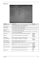
... Password User Password HDD Password Change Supervisor Password Change HDD Password TPM Support TPM State TPM Operation TPM Enabled Status TPM Active Status TPM Owner Status Removable Device Boot BIOS Write Protect Chassis Open Warning Chassis Open Description Option This item indicates whether a supervisor password has been set . Disabled Use this option and press to be active or not. Enabled Disabled This item enables or disables the warning if the case is set to access the sub menu. If not, Not Installed displays. If not, Not Installed displays...
... Password User Password HDD Password Change Supervisor Password Change HDD Password TPM Support TPM State TPM Operation TPM Enabled Status TPM Active Status TPM Owner Status Removable Device Boot BIOS Write Protect Chassis Open Warning Chassis Open Description Option This item indicates whether a supervisor password has been set . Disabled Use this option and press to be active or not. Enabled Disabled This item enables or disables the warning if the case is set to access the sub menu. If not, Not Installed displays. If not, Not Installed displays...
Veriton X461x Desktop Series Service Guide
Page 33
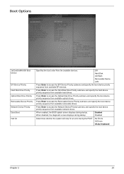
...Press Enter to access the EFI Device Priority submenu and specify the boot device priority sequence from the available devices. EFI Hard Disk CD^DVD Removable Device LAN Press Enter to access the Removable Device Priority submenu and specify the boot device priority sequence from available hard drives. No Errors All Errors All,but keyboard Chapter 2 25 When enabled, the BIOS splash screen displays during startup. Boot Options 1st/2nd/3rd/4th/5th Boot Device EFI Device Priority Hard Disk Drive Priority Optical Disk Drive Priority Removable Device Priority Network Device Priority...
...Press Enter to access the EFI Device Priority submenu and specify the boot device priority sequence from the available devices. EFI Hard Disk CD^DVD Removable Device LAN Press Enter to access the Removable Device Priority submenu and specify the boot device priority sequence from available hard drives. No Errors All Errors All,but keyboard Chapter 2 25 When enabled, the BIOS splash screen displays during startup. Boot Options 1st/2nd/3rd/4th/5th Boot Device EFI Device Priority Hard Disk Drive Priority Optical Disk Drive Priority Removable Device Priority Network Device Priority...

Veriton X461x Desktop Series Service Guide
Page 87
... to "Power System check" on page 80 and "Beep Codes" on how to troubleshoot system hardware problems. Hardware Diagnostic Procedure IMPORTANT:The diagnostic tests described in as much detail as possible. 2. NonAcerproducts, prototype cards, or modified options can give false errors and invalid systemresponses. 1. Chapter 4 System Troubleshooting This chapter provides instructions on page 81 to determine which corrective action to recreate the failure by running the diagnostic tests or...
... to "Power System check" on page 80 and "Beep Codes" on how to troubleshoot system hardware problems. Hardware Diagnostic Procedure IMPORTANT:The diagnostic tests described in as much detail as possible. 2. NonAcerproducts, prototype cards, or modified options can give false errors and invalid systemresponses. 1. Chapter 4 System Troubleshooting This chapter provides instructions on page 81 to determine which corrective action to recreate the failure by running the diagnostic tests or...
Veriton X461x Desktop Series Service Guide
Page 90
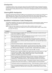
... copied from add-in scratch CMOS. Main BIOS checksum is uncompressed into memory. The Runtime module is tested. Save power-on CPUID value in PCI devices. Disable CACHE before system memory is given to it. Verify that checkpoints may differ between different platforms based on system configuration.Checkpoints may appear on a LED display. Performs main BIOS checksum and updates recovery status accordingly. If BIOS recovery is enabled. Restore CPUID value...
... copied from add-in scratch CMOS. Main BIOS checksum is uncompressed into memory. The Runtime module is tested. Save power-on CPUID value in PCI devices. Disable CACHE before system memory is given to it. Verify that checkpoints may differ between different platforms based on system configuration.Checkpoints may appear on a LED display. Performs main BIOS checksum and updates recovery status accordingly. If BIOS recovery is enabled. Restore CPUID value...
Veriton X461x Desktop Series Service Guide
Page 92
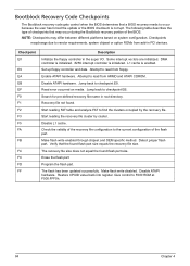
... recovery file configuration to vendor requirements, system chipset or option ROMs from add-in the super I/O. The flash has been updated successfully. Checkpoints maychange due to the current configuration of the BIOS. DMA controller is initialized. 8259 interrupt controller is enabled. Jump back to F000 ROM at F000:FFF0h. 84 Chapter 4 Make flash write disabled. Bootblock Recovery Code Checkpoints The Bootblock recovery code gets control when the BIOS determines that the found flash part...
... recovery file configuration to vendor requirements, system chipset or option ROMs from add-in the super I/O. The flash has been updated successfully. Checkpoints maychange due to the current configuration of the BIOS. DMA controller is initialized. 8259 interrupt controller is enabled. Jump back to F000 ROM at F000:FFF0h. 84 Chapter 4 Make flash write disabled. Bootblock Recovery Code Checkpoints The Bootblock recovery code gets control when the BIOS determines that the found flash part...

Veriton X461x Desktop Series Service Guide
Page 93
... USB flash drive(Disk on Key, DOK). 2. Chapter 4 85 The BIOS recovery function will auto reboot. 6. After BIOS is used to flash update a BIOS from the boot block. Please enter the setup menu to flash BIOS ROM. 1. The following is the process that user should follow to load default after system reboot. This is updated completely, the system will be used to update a BIOS image without the need to boot to the system. 3. Install the DOK to an operating system. BIOS Recovery AMIBIOS supports a "recovery flash" mode, which...
... USB flash drive(Disk on Key, DOK). 2. Chapter 4 85 The BIOS recovery function will auto reboot. 6. After BIOS is used to flash update a BIOS from the boot block. Please enter the setup menu to flash BIOS ROM. 1. The following is the process that user should follow to load default after system reboot. This is updated completely, the system will be used to update a BIOS image without the need to boot to the system. 3. Install the DOK to an operating system. BIOS Recovery AMIBIOS supports a "recovery flash" mode, which...
Veriton X461x Desktop Series Service Guide
Page 95
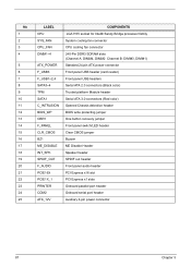
... connector CPU cooling fan connector 240-Pin DDR3 SDRAM slots (Channel A: DIMM4, DIMM2 Channel B: DIMM3, DIMM1) Standard 24-pin ATX power connector Front panel USB header (card reader) Front panel USB headers Serial ATA 2.0 connectors (Black color) Trusted platform Module header Serial ATA 3.0 connectors (Red color) Opened Chassis detective header BIOS write protecting jumper One button recovery jumper Front panel switch/LED header Clear CMOS jumper Buzzer ME Disable Header Speaker header SPDIF out header Front panel audio header PCI Express x16 slot PCI Express x1 slots Onboard parallel port...
... connector CPU cooling fan connector 240-Pin DDR3 SDRAM slots (Channel A: DIMM4, DIMM2 Channel B: DIMM3, DIMM1) Standard 24-pin ATX power connector Front panel USB header (card reader) Front panel USB headers Serial ATA 2.0 connectors (Black color) Trusted platform Module header Serial ATA 3.0 connectors (Red color) Opened Chassis detective header BIOS write protecting jumper One button recovery jumper Front panel switch/LED header Clear CMOS jumper Buzzer ME Disable Header Speaker header SPDIF out header Front panel audio header PCI Express x16 slot PCI Express x1 slots Onboard parallel port...

Veriton X461x Desktop Series Service Guide
Page 96
... show a 2-pin jumper. Pins1 and 2 are numbered. Jumper Setting The section explains how to set jumper for correct configuration of the motherboard jumpers. If you remove the jumpercap, or place the jumper cap on just one pin are SHORT. Checking Jumper Settings The following illustration shows the location of the mainboard. Setting Jumper Use the motherboard jumpers to set system configuration options. This illustration shows a 3-pin jumper. Jumpers with more Than one pin,the jumper is OPEN. When setting the jumpers, ensure...
... show a 2-pin jumper. Pins1 and 2 are numbered. Jumper Setting The section explains how to set jumper for correct configuration of the motherboard jumpers. If you remove the jumpercap, or place the jumper cap on just one pin are SHORT. Checking Jumper Settings The following illustration shows the location of the mainboard. Setting Jumper Use the motherboard jumpers to set system configuration options. This illustration shows a 3-pin jumper. Jumpers with more Than one pin,the jumper is OPEN. When setting the jumpers, ensure...

Veriton X461x Desktop Series Service Guide
Page 97
Jumper Settings Jumper CLR_CMOS ME_DISABLE BIOS_WP OBR Type 3-pin Description CLEAR CMOS 3-pin Disable ME Setting (default) 1-2: NORMAL 2-3: CLEAR Before clearing the CMOS, make sure to turn the system off. 1-2: NORMAL 2-3: ME disable 3-pin BIOS Flash protect 1-2: BIOS_WP 2-3: NORMAL 2-pin 1-2: Closed 2-3: Open Active No Active (Default) CLR_CMOS 89 Chapter 5
Jumper Settings Jumper CLR_CMOS ME_DISABLE BIOS_WP OBR Type 3-pin Description CLEAR CMOS 3-pin Disable ME Setting (default) 1-2: NORMAL 2-3: CLEAR Before clearing the CMOS, make sure to turn the system off. 1-2: NORMAL 2-3: ME disable 3-pin BIOS Flash protect 1-2: BIOS_WP 2-3: NORMAL 2-pin 1-2: Closed 2-3: Open Active No Active (Default) CLR_CMOS 89 Chapter 5


