Aspire X1700 / Veriton X270 Service Guide
Page 7
...Panel 28 Removing the Front Bezel 29 Removing the Heat Sink Fan Assembly 30 Removing the Processor 32 Removing the Optical Drive 34 Removing the Hard Disk Drive 37 Removing the Power Supply 40 Removing the Memory Modules 42 Removing the VGA Card (X1700 model) 43 Removing ... Boards 45 Removing the Mainboard 49 Removing the Power Switch and LED Cables 51 Removing the LAN Activity and HDD LED Cables (X270 model) 54 System Troubleshooting 55 Hardware Diagnostic Procedure 55 System Check Procedures 56 Power System Check 56 System External Inspection 56 System ...
...Panel 28 Removing the Front Bezel 29 Removing the Heat Sink Fan Assembly 30 Removing the Processor 32 Removing the Optical Drive 34 Removing the Hard Disk Drive 37 Removing the Power Supply 40 Removing the Memory Modules 42 Removing the VGA Card (X1700 model) 43 Removing ... Boards 45 Removing the Mainboard 49 Removing the Power Switch and LED Cables 51 Removing the LAN Activity and HDD LED Cables (X270 model) 54 System Troubleshooting 55 Hardware Diagnostic Procedure 55 System Check Procedures 56 Power System Check 56 System External Inspection 56 System ...
Aspire X1700 / Veriton X270 Service Guide
Page 9
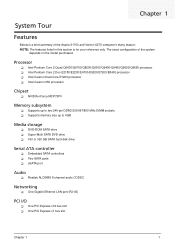
...-533/667/800 MHz DIMM sockets Supports memory size up to 4GB Media storage DVD-ROM SATA drive Super-Multi SATA DVD drive 160 or 320 GB SATA hard disk drive Serial ATA controller Embedded SATA controllers Two SATA ports eSATA port Audio Realtek ALC888S 8-channel...-45) PCI I/O One PCI Express x16 bus slot One PCI Express x1 bus slot Chapter 1 1 The exact configuration of the Aspire X1700 and Veriton X270 computer's many feature: NOTE: The features listed in this section is for your reference only.
...-533/667/800 MHz DIMM sockets Supports memory size up to 4GB Media storage DVD-ROM SATA drive Super-Multi SATA DVD drive 160 or 320 GB SATA hard disk drive Serial ATA controller Embedded SATA controllers Two SATA ports eSATA port Audio Realtek ALC888S 8-channel...-45) PCI I/O One PCI Express x16 bus slot One PCI Express x1 bus slot Chapter 1 1 The exact configuration of the Aspire X1700 and Veriton X270 computer's many feature: NOTE: The features listed in this section is for your reference only.
Aspire X1700 / Veriton X270 Service Guide
Page 20
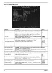
... shortening Enabled or skipping certain standard booting process. Enabled Disabled 1st/2nd/3rd/4th Boot Device Specifies the boot order from available hard drives. Bootup Num-Lock Selects power on the screen or an alarm beep when someone attempts to display error beeps or messages during... USB device enumeration. Disabled Enabled Hard Disk Write Protect Enables or disables the hard disk write protect feature. Hard Disk CD^DVD Removable Device LAN Hard Disk Drive Priority Press Enter to no, it lets the OS configure Plug and Play ...
... shortening Enabled or skipping certain standard booting process. Enabled Disabled 1st/2nd/3rd/4th Boot Device Specifies the boot order from available hard drives. Bootup Num-Lock Selects power on the screen or an alarm beep when someone attempts to display error beeps or messages during... USB device enumeration. Disabled Enabled Hard Disk Write Protect Enables or disables the hard disk write protect feature. Hard Disk CD^DVD Removable Device LAN Hard Disk Drive Priority Press Enter to no, it lets the OS configure Plug and Play ...
Aspire X1700 / Veriton X270 Service Guide
Page 45
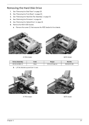
Remove the HDD-ODD bracket. Remove the screw (C) that secures the HDD bracket to 6.5 kgf-cm X270 model Part No. 86.00J44.C60 X1700 model Chapter 3 X270 model 37 See "Removing the Side Panel" on page 32. 5. a. Torque 5.5 to the chassis. See "Removing the Processor" on page 28. 2. See "Removing the Heat Sink Fan Assembly" on page 29. 3. X1700 model Screw (Quantity) #6-32 L6 BZN (1) Color Silver b. Removing the Hard Disk Drive 1. See "Removing the Front Bezel" on page 30. 4. Lift the bracket up and turn it over. See "Removing the Optical Drive" on page 34. 6.
Remove the HDD-ODD bracket. Remove the screw (C) that secures the HDD bracket to 6.5 kgf-cm X270 model Part No. 86.00J44.C60 X1700 model Chapter 3 X270 model 37 See "Removing the Side Panel" on page 32. 5. a. Torque 5.5 to the chassis. See "Removing the Processor" on page 28. 2. See "Removing the Heat Sink Fan Assembly" on page 29. 3. X1700 model Screw (Quantity) #6-32 L6 BZN (1) Color Silver b. Removing the Hard Disk Drive 1. See "Removing the Front Bezel" on page 30. 4. Lift the bracket up and turn it over. See "Removing the Optical Drive" on page 34. 6.
Aspire X1700 / Veriton X270 Service Guide
Page 46
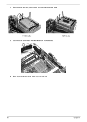
7. X270 model 9. Place the bracket on a clean, static-free work surface. 38 Chapter 3 Disconnect the data and power cables from the rear of the data cable from the mainboard. Disconnect the other end of the hard drive. X1700 model 8.
7. X270 model 9. Place the bracket on a clean, static-free work surface. 38 Chapter 3 Disconnect the data and power cables from the rear of the data cable from the mainboard. Disconnect the other end of the hard drive. X1700 model 8.
Aspire X1700 / Veriton X270 Service Guide
Page 48
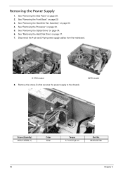
...See "Removing the Heat Sink Fan Assembly" on page 28. 2. X1700 model 8. X270 model Screw (Quantity) #6-32 L6 BZN (1) Color Silver Torque 5.7 to the chassis. See "Removing the Processor" on page 34. 6. See "Removing the Optical Drive" on page 32. 5. Remove the screw (C) that secures the power supply to ...6.3 kgf-cm Part No. 86.00J44.C60 40 Chapter 3 See "Removing the Hard Disk Drive" on page 29. 3. See "Removing the Front Bezel" on page 37. 7. Disconnect the 4-pin and 24-pin power supply cables from the...
...See "Removing the Heat Sink Fan Assembly" on page 28. 2. X1700 model 8. X270 model Screw (Quantity) #6-32 L6 BZN (1) Color Silver Torque 5.7 to the chassis. See "Removing the Processor" on page 34. 6. See "Removing the Optical Drive" on page 32. 5. Remove the screw (C) that secures the power supply to ...6.3 kgf-cm Part No. 86.00J44.C60 40 Chapter 3 See "Removing the Hard Disk Drive" on page 29. 3. See "Removing the Front Bezel" on page 37. 7. Disconnect the 4-pin and 24-pin power supply cables from the...

Aspire X1700 / Veriton X270 Service Guide
Page 50
...X270 model 42 Chapter 3 Removing the Memory Modules IMPORTANT:Before removing any DIMM from the chassis (2). See "Removing the Heat Sink Fan Assembly" on page 32. 5. Press the holding clips on both sides of the DIMM slot outward to create a backup file of all important data. 1. See "Removing the Hard Disk Drive..." on page 34. 6. Gently pull the DIMM upward to pull it away from the memory board, make sure to release the DIMM (1). 8. See "Removing the Optical Drive" on page 37. 7. See "Removing the Side Panel...
...X270 model 42 Chapter 3 Removing the Memory Modules IMPORTANT:Before removing any DIMM from the chassis (2). See "Removing the Heat Sink Fan Assembly" on page 32. 5. Press the holding clips on both sides of the DIMM slot outward to create a backup file of all important data. 1. See "Removing the Hard Disk Drive..." on page 34. 6. Gently pull the DIMM upward to pull it away from the memory board, make sure to release the DIMM (1). 8. See "Removing the Optical Drive" on page 37. 7. See "Removing the Side Panel...

Aspire X1700 / Veriton X270 Service Guide
Page 51
See "Removing the Processor" on page 37. 7. See "Removing the Hard Disk Drive" on page 32. 5. Part No. 86.9A5G6.162 Chapter 3 43 See "Removing the Optical Drive" on page 29. 3. Remove the screw (E) that secures the card to remove it from the mainboard. See "Removing the Front Bezel" on page 34. 6. Gently pull the card to the chassis. See "Removing the Side Panel" on page 30. 4. Screw (Quantity) #6-32 5MM NI (1) Color Silver Torque 5.5 to 6.5 kgf-cm 8. See "Removing the Heat Sink Fan Assembly" on page 28. 2. Removing the VGA Card (X1700 model) 1.
See "Removing the Processor" on page 37. 7. See "Removing the Hard Disk Drive" on page 32. 5. Part No. 86.9A5G6.162 Chapter 3 43 See "Removing the Optical Drive" on page 29. 3. Remove the screw (E) that secures the card to remove it from the mainboard. See "Removing the Front Bezel" on page 34. 6. Gently pull the card to the chassis. See "Removing the Side Panel" on page 30. 4. Screw (Quantity) #6-32 5MM NI (1) Color Silver Torque 5.5 to 6.5 kgf-cm 8. See "Removing the Heat Sink Fan Assembly" on page 28. 2. Removing the VGA Card (X1700 model) 1.

Aspire X1700 / Veriton X270 Service Guide
Page 52
Gently pull the card to the chassis. See "Removing the Heat Sink Fan Assembly" on page 34. 6. Remove the screw (E) that secures the card to remove it from the mainboard. Part No. 86.9A5G6.162 44 Chapter 3 See "Removing the Optical Drive" on page 30. 4. Screw (Quantity) #6-32 5MM NI (1) Color Silver Torque 5.5 to 6.5 kgf-cm 8. Removing the TV Tuner Card (X1700 model) 1. See "Removing the Processor" on page 29. 3. See "Removing the Front Bezel" on page 32. 5. See "Removing the Side Panel" on page 37. 7. See "Removing the Hard Disk Drive" on page 28. 2.
Gently pull the card to the chassis. See "Removing the Heat Sink Fan Assembly" on page 34. 6. Remove the screw (E) that secures the card to remove it from the mainboard. Part No. 86.9A5G6.162 44 Chapter 3 See "Removing the Optical Drive" on page 30. 4. Screw (Quantity) #6-32 5MM NI (1) Color Silver Torque 5.5 to 6.5 kgf-cm 8. Removing the TV Tuner Card (X1700 model) 1. See "Removing the Processor" on page 29. 3. See "Removing the Front Bezel" on page 32. 5. See "Removing the Side Panel" on page 37. 7. See "Removing the Hard Disk Drive" on page 28. 2.

Aspire X1700 / Veriton X270 Service Guide
Page 53
Open the cable retention clip. See "Removing the Optical Drive" on page 29. 3. Disconnect one end of the USB, 1394, and audio cables from the I /O and Card Reader Boards 1. See "Removing the Front Bezel" on page 34. 6. See "Removing the Heat Sink Fan Assembly" on page 42. 8. See "Removing the Memory Modules" on page 30. 4. X1700 model 9. See "Removing the Processor" on page 28. 2. See "Removing the Side Panel" on page 32. 5. See "Removing the Hard Disk Drive" on page 37. 7. X270 model Chapter 3 45 Removing the Front I /O and card reader boards.
Open the cable retention clip. See "Removing the Optical Drive" on page 29. 3. Disconnect one end of the USB, 1394, and audio cables from the I /O and Card Reader Boards 1. See "Removing the Front Bezel" on page 34. 6. See "Removing the Heat Sink Fan Assembly" on page 42. 8. See "Removing the Memory Modules" on page 30. 4. X1700 model 9. See "Removing the Processor" on page 28. 2. See "Removing the Side Panel" on page 32. 5. See "Removing the Hard Disk Drive" on page 37. 7. X270 model Chapter 3 45 Removing the Front I /O and card reader boards.

Aspire X1700 / Veriton X270 Service Guide
Page 57
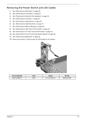
See "Removing the Heat Sink Fan Assembly" on page 37. 7. See "Removing the Hard Disk Drive" on page 30. 4. Remove the screw (B) on page 44. 10. See "Removing the TV Tuner Card (X1700 model)" on the rear panel. See "Removing the ... (X1700 model)" on page 32. 5. Disconnect the LED cable from the mainboard. 12. See "Removing the Front Bezel" on page 34. 6. See "Removing the Optical Drive" on page 29. 3. See "Removing the Memory Modules" on page 45. 11. Screw (Quantity) M3xL5 (1) Color Black Torque 5.5 to 6.5 kgf-cm Part No. 86.1A324...
See "Removing the Heat Sink Fan Assembly" on page 37. 7. See "Removing the Hard Disk Drive" on page 30. 4. Remove the screw (B) on page 44. 10. See "Removing the TV Tuner Card (X1700 model)" on the rear panel. See "Removing the ... (X1700 model)" on page 32. 5. Disconnect the LED cable from the mainboard. 12. See "Removing the Front Bezel" on page 34. 6. See "Removing the Optical Drive" on page 29. 3. See "Removing the Memory Modules" on page 45. 11. Screw (Quantity) M3xL5 (1) Color Black Torque 5.5 to 6.5 kgf-cm Part No. 86.1A324...
Aspire X1700 / Veriton X270 Service Guide
Page 59
..." on page 49. 12. Remove the screw (C) that secures the LED bracket to 6.3 kgf-cm Part No. 86.00J44.C60 Chapter 3 51 See "Removing the Hard Disk Drive" on page 44. 10. See "Removing the TV Tuner Card (X1700 model)" on page 37. 7. See "Removing the Optical...
..." on page 49. 12. Remove the screw (C) that secures the LED bracket to 6.3 kgf-cm Part No. 86.00J44.C60 Chapter 3 51 See "Removing the Hard Disk Drive" on page 44. 10. See "Removing the TV Tuner Card (X1700 model)" on page 37. 7. See "Removing the Optical...
Aspire X1700 / Veriton X270 Service Guide
Page 62
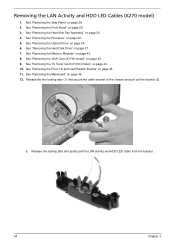
... the bracket (2). See "Removing the Processor" on page 49. 12. See "Removing the Front I/O and Card Reader Boards" on page 37. 7. See "Removing the Hard Disk Drive" on page 45. 11. See "Removing the VGA Card (X1700 model)" on page 44. 10. See "Removing the TV Tuner Card (X1700 model)" on page... 43. 9. Removing the LAN Activity and HDD LED Cables (X270 model) 1. See "Removing the Heat Sink Fan Assembly" on page 30. 4. Release the locking tabs ...
... the bracket (2). See "Removing the Processor" on page 49. 12. See "Removing the Front I/O and Card Reader Boards" on page 37. 7. See "Removing the Hard Disk Drive" on page 45. 11. See "Removing the VGA Card (X1700 model)" on page 44. 10. See "Removing the TV Tuner Card (X1700 model)" on page... 43. 9. Removing the LAN Activity and HDD LED Cables (X270 model) 1. See "Removing the Heat Sink Fan Assembly" on page 30. 4. Release the locking tabs ...
Aspire X1700 / Veriton X270 Service Guide
Page 87
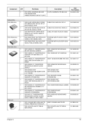
... Part Name Description 1 CPU INTEL CELERON 450 2.XG IC CPU CONROE LITE 450 2.2G 512K 800FSB 35W HH80557RG049512 891507 SLAFZ Acer Part Number KC.D0001.450 Optical drive DVD-RW drive 1 1 1 DVD-ROM drive 1 1 Hard disk drive 1 1 1 1 1 1 1 1 1 1 Heat sink 1 ODD HLDS SUPER-MULTI DRIVE HH LABELFLASH 16X GH-15F LF BLACK BEZEL SATA ODD SONY SUPER-MULTI...
... Part Name Description 1 CPU INTEL CELERON 450 2.XG IC CPU CONROE LITE 450 2.2G 512K 800FSB 35W HH80557RG049512 891507 SLAFZ Acer Part Number KC.D0001.450 Optical drive DVD-RW drive 1 1 1 DVD-ROM drive 1 1 Hard disk drive 1 1 1 1 1 1 1 1 1 1 Heat sink 1 ODD HLDS SUPER-MULTI DRIVE HH LABELFLASH 16X GH-15F LF BLACK BEZEL SATA ODD SONY SUPER-MULTI...
Aspire X1700 / Veriton X270 Service Guide
Page 97
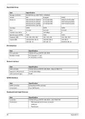
Hard Disk Drive Item Storage controller Vendor Model no. Interface Size Transfer rate (Gb/s) Spindle speed (RPM) Capacity (GB) Cache (MB) Specification NVIDIA NForce MCP73PV 1048 BGA WD ...
Hard Disk Drive Item Storage controller Vendor Model no. Interface Size Transfer rate (Gb/s) Spindle speed (RPM) Capacity (GB) Cache (MB) Specification NVIDIA NForce MCP73PV 1048 BGA WD ...


