TravelMate 8210 User's Guide EN
Page 35
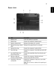
...for removal. latch 5 Optical drive bay Houses the computer's optical drive. 6 Hard disk bay Houses the computer's hard disk (secured with screws). 7 Acer DASP (Disk AntiShock Protection) Protects the hard disk drive from shocks and bumps. 8 Wireless LAN and Houses the computer's WLAN and main memory compartments memory... (secured with screws). 9 Ventilation slots and cooling fan Enable the computer to stay cool, even after prolonged use. Note: Do not cover or obstruct the opening of the...
...for removal. latch 5 Optical drive bay Houses the computer's optical drive. 6 Hard disk bay Houses the computer's hard disk (secured with screws). 7 Acer DASP (Disk AntiShock Protection) Protects the hard disk drive from shocks and bumps. 8 Wireless LAN and Houses the computer's WLAN and main memory compartments memory... (secured with screws). 9 Ventilation slots and cooling fan Enable the computer to stay cool, even after prolonged use. Note: Do not cover or obstruct the opening of the...

TravelMate 8210 Service Guide
Page 19
Do not cover or obstruct the opening of the cooling fan fan. memory compartments 9 Ventilation slots and Keep the computer cool. Shock Protection) 8 Wireless LAN and Houses the computer's Wireless LAN and main memory. Note Chapter 1 9 Protects ... bay release latch Releases the optical drive for removal. 5 Optical drive bay Houses the computer's optical drive. 6 Hard disk bay Houses the computer's hard disk. 7 Acer DASP (disk Anti-
Do not cover or obstruct the opening of the cooling fan fan. memory compartments 9 Ventilation slots and Keep the computer cool. Shock Protection) 8 Wireless LAN and Houses the computer's Wireless LAN and main memory. Note Chapter 1 9 Protects ... bay release latch Releases the optical drive for removal. 5 Optical drive bay Houses the computer's optical drive. 6 Hard disk bay Houses the computer's hard disk. 7 Acer DASP (disk Anti-

TravelMate 8210 Service Guide
Page 73
.... 18. Finally, remove the two hexagonal screws on the rear side of these 18 screws secures the fan (marked in red). 17. Release the connector and disconnect the Smart Card reader cable. 20. Disconnect the fan cable. 63 Chapter 3 Disconnect the speaker set cable. 22. To separate the upper case from the...
.... 18. Finally, remove the two hexagonal screws on the rear side of these 18 screws secures the fan (marked in red). 17. Release the connector and disconnect the Smart Card reader cable. 20. Disconnect the fan cable. 63 Chapter 3 Disconnect the speaker set cable. 22. To separate the upper case from the...

TravelMate 8210 Service Guide
Page 74
Then detach the fan. 26. Remove the two screws fastening the modem board. 27. Chapter 3 64 Release the screw fastening the CPU by rotating the screw counter clockwise then .... Remove the screw fastening the charge board then detach it from the main board carefully then disconnect it . 31. Remove the two screws fastening the fan. 25. Release the five screws fastening the heatsink then detach the heatsink. 32. Detach the modem board from the main board. Separate the main board...
Then detach the fan. 26. Remove the two screws fastening the modem board. 27. Chapter 3 64 Release the screw fastening the CPU by rotating the screw counter clockwise then .... Remove the screw fastening the charge board then detach it from the main board carefully then disconnect it . 31. Remove the two screws fastening the fan. 25. Release the five screws fastening the heatsink then detach the heatsink. 32. Detach the modem board from the main board. Separate the main board...

TravelMate 8210 Service Guide
Page 96
Part Three of Top View Item CN20 CN21 CN22 CN23 CN24 CN25 CN26 CN28 CN29 CN30 CN31 Description SVIDEO Item CN32 Docking CN33 DVI-D CRT connector CN37 CN38 mini card connector U37 RJ45 W/ LED U40 Battery connector (seven U41 pin) Fan connector U43 Media connector (M/B side) U44 DDR2 (9.2MM) U48 DDR2 (5.2MM) U57 Description RTC battery connector (two pin) HDD connector (22 pin SATA) Connector SMD FFC 30 pin Bluetooth module connector (five pin) V-RAM V-RAM VGA chip CPU North bridge South bridge BIOS Chapter 5 86
Part Three of Top View Item CN20 CN21 CN22 CN23 CN24 CN25 CN26 CN28 CN29 CN30 CN31 Description SVIDEO Item CN32 Docking CN33 DVI-D CRT connector CN37 CN38 mini card connector U37 RJ45 W/ LED U40 Battery connector (seven U41 pin) Fan connector U43 Media connector (M/B side) U44 DDR2 (9.2MM) U48 DDR2 (5.2MM) U57 Description RTC battery connector (two pin) HDD connector (22 pin SATA) Connector SMD FFC 30 pin Bluetooth module connector (five pin) V-RAM V-RAM VGA chip CPU North bridge South bridge BIOS Chapter 5 86


