
TravelMate 8100 Service Guide
Page 6
... Module and Upper Case 57 Disassembling the LCD Module 60 Disassembling the External Modules 62 Chapter 4 Troubleshooting 63 System Check Procedures 64 Power-On Self-Test (POST) Error Message 67 Index of Error Messages 68 Phoenix BIOS Beep Codes 70 Index of Symptom-to-FRU ... Layout 82 Chapter 6 FRU(Field Replaceable Unit)List 84 Exploded Diagram 85 FRU List 87 Appendix A Model Definition and Configuration 95 TravelMate 8100 Series 95 Appendix B Test Compatible Components 96 Microsoft® Windows® XP Pro Environment Test 97 Appendix C Online Support Information 99 Chapter 1...
... Module and Upper Case 57 Disassembling the LCD Module 60 Disassembling the External Modules 62 Chapter 4 Troubleshooting 63 System Check Procedures 64 Power-On Self-Test (POST) Error Message 67 Index of Error Messages 68 Phoenix BIOS Beep Codes 70 Index of Symptom-to-FRU ... Layout 82 Chapter 6 FRU(Field Replaceable Unit)List 84 Exploded Diagram 85 FRU List 87 Appendix A Model Definition and Configuration 95 TravelMate 8100 Series 95 Appendix B Test Compatible Components 96 Microsoft® Windows® XP Pro Environment Test 97 Appendix C Online Support Information 99 Chapter 1...

TravelMate 8100 Service Guide
Page 12
...and right buttons function like a computer mouse. Turns on and off 3 Status indicators Light-Emitting Diodes (LEDs) that turn on the computer power. 6 Chapter 1 Outlook View A general introduction of ports allow you to show the status of the computer's functions and components. 4 ...right mouse buttons; Front Open View # Icon Item Description 1 Display screen Also called LCD (liquid-crystal display), displays computer output. 2 Power button Turns the computer on and off to connect peripheral devices, as a 4-way scroll button. 7 Launch keys Special keys for your...
...and right buttons function like a computer mouse. Turns on and off 3 Status indicators Light-Emitting Diodes (LEDs) that turn on the computer power. 6 Chapter 1 Outlook View A general introduction of ports allow you to show the status of the computer's functions and components. 4 ...right mouse buttons; Front Open View # Icon Item Description 1 Display screen Also called LCD (liquid-crystal display), displays computer output. 2 Power button Turns the computer on and off to connect peripheral devices, as a 4-way scroll button. 7 Launch keys Special keys for your...

TravelMate 8100 Service Guide
Page 13
infrared printer and IR-aware computer) Power indicator Lights when the computer is being charged 7 # Item 8 Speaker/Line-Out/ Headphone jack S/PDIF out * COnnects to http://www.techweb.com/encyclopedia/defineterm.jhtml?...
infrared printer and IR-aware computer) Power indicator Lights when the computer is being charged 7 # Item 8 Speaker/Line-Out/ Headphone jack S/PDIF out * COnnects to http://www.techweb.com/encyclopedia/defineterm.jhtml?...

TravelMate 8100 Service Guide
Page 15
... drive Internal optical drive;accepts CDs or DVDs depending on the optical drive type. 3 N/A LED indicator Lights up when the optical drive is turned off. 6 Power jack Connects to an AC adapter. 7 Security keylock Connects to a Kensington-compatible computer security lock. button 5 N/A Emergency Eject hole Ejects the optical drive tray when...
... drive Internal optical drive;accepts CDs or DVDs depending on the optical drive type. 3 N/A LED indicator Lights up when the optical drive is turned off. 6 Power jack Connects to an AC adapter. 7 Security keylock Connects to a Kensington-compatible computer security lock. button 5 N/A Emergency Eject hole Ejects the optical drive tray when...

TravelMate 8100 Service Guide
Page 18
... LAN communication. 12 Chapter 1 Battery indicator Lights when the battery is being charged Bluetooth communications Wireless communication Indicates that (optional) Bluetooth is activated. Media Activity Power indicator Lights when the disc or AcerMedia is enabled. Indicators The computer has three easy-to-read status icons on the upper-left above the...
... LAN communication. 12 Chapter 1 Battery indicator Lights when the battery is being charged Bluetooth communications Wireless communication Indicates that (optional) Bluetooth is activated. Media Activity Power indicator Lights when the disc or AcerMedia is enabled. Indicators The computer has three easy-to-read status icons on the upper-left above the...

TravelMate 8100 Service Guide
Page 24
...brightness, volume output and the BIOS utility. Fn-w Volume up Increases the speaker volume. 18 Chapter 1 Acer ePowerManagement Launches the Acer ePowerManagement in the Acer eManager set by the Acer Empowering key. Turns the display screen backlight off . To activate hot keys, press and hold the Fn ...key before pressing the other key in Sleep mode. Turns the internal touchpad on and off to save power....
...brightness, volume output and the BIOS utility. Fn-w Volume up Increases the speaker volume. 18 Chapter 1 Acer ePowerManagement Launches the Acer ePowerManagement in the Acer eManager set by the Acer Empowering key. Turns the display screen backlight off . To activate hot keys, press and hold the Fn ...key before pressing the other key in Sleep mode. Turns the internal touchpad on and off to save power....

TravelMate 8100 Service Guide
Page 33
... CD, CD-EXTRA(CD+), CD-Text DVD: DVD-VIDEO, DVD-ROM, DVDR(3.9GB,4.7GB), DVDRW(Ver1.1), DVD-RAM, DVD+R,DVD+R DL, DVD+RW Loading mechanism Power Consumption Operating Voltage Tray Max. 1800 mA +5V+/-0.25V Tray Max. 1.9A +5V+/-5% Audio Interface Item Audio Controller Audio onboard or optional Mono or Stereo...
... CD, CD-EXTRA(CD+), CD-Text DVD: DVD-VIDEO, DVD-ROM, DVDR(3.9GB,4.7GB), DVDRW(Ver1.1), DVD-RAM, DVD+R,DVD+R DL, DVD+RW Loading mechanism Power Consumption Operating Voltage Tray Max. 1800 mA +5V+/-0.25V Tray Max. 1.9A +5V+/-5% Audio Interface Item Audio Controller Audio onboard or optional Mono or Stereo...
TravelMate 8100 Service Guide
Page 34
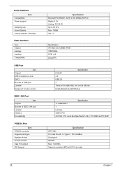
Audio Interface Item Compatibility Power support Sampling rate Sound Quality Internal speaker / Quantity Video Interface Item Chipset package interface Compatibility USB Port Item Chipset USB Compliancy Level OHCI Number of ...
Audio Interface Item Compatibility Power support Sampling rate Sound Quality Internal speaker / Quantity Video Interface Item Chipset package interface Compatibility USB Port Item Chipset USB Compliancy Level OHCI Number of ...

TravelMate 8100 Service Guide
Page 36
... Display Mode Typical White Luminance (cd/m2) also called Brightness Contrast Ratio Response Time (Optical Rise Time+Fall Time)msec Voltage of Power Supply Power Consumption (watt) Weight Physical Size(mm) Electrical Interface Support Color Viewing Angle (degree) Horizontal: Right/Left Vertial: Upper/Lower Temperature ... voltage (V, rms) Output current (mA, rms) Output voltage frequency (k Hz) AC Adaptor Item Vendor & model name Input Voltage input power rating Frequency Maximum input AC current 30 Specification SUMIDA TWS-449-171 Duty 30~100% 9~21V 330mA typ 650Vrms typ 3.0~6.0mA 45~65KHz ...
... Display Mode Typical White Luminance (cd/m2) also called Brightness Contrast Ratio Response Time (Optical Rise Time+Fall Time)msec Voltage of Power Supply Power Consumption (watt) Weight Physical Size(mm) Electrical Interface Support Color Viewing Angle (degree) Horizontal: Right/Left Vertial: Upper/Lower Temperature ... voltage (V, rms) Output current (mA, rms) Output voltage frequency (k Hz) AC Adaptor Item Vendor & model name Input Voltage input power rating Frequency Maximum input AC current 30 Specification SUMIDA TWS-449-171 Duty 30~100% 9~21V 330mA typ 650Vrms typ 3.0~6.0mA 45~65KHz ...

TravelMate 8100 Service Guide
Page 37
... start) 220A@100VAC/60Hz(cold start) 85% (Min), 88%(Typical) with the AC input set Power Down VGA Suspend PCMCIA Suspend Audio Power Down Hard Disk Power Down CD-ROM Power Down Super I/O Low Power mode Also called Hibernate state. Off (G3) Soft Off (G2/S5) Working (G0/S0) Suspend... to RAM (S3)(Sleeping State) Save to power off completely. Power Management All devices in the system are turned off the whole system. OS initiated shutdown. AC Adaptor Item Inrush current Efficiency System Power Management ACPI mode Mech. Chapter 1 31 CPU set at the normal ...
... start) 220A@100VAC/60Hz(cold start) 85% (Min), 88%(Typical) with the AC input set Power Down VGA Suspend PCMCIA Suspend Audio Power Down Hard Disk Power Down CD-ROM Power Down Super I/O Low Power mode Also called Hibernate state. Off (G3) Soft Off (G2/S5) Working (G0/S0) Suspend... to RAM (S3)(Sleeping State) Save to power off completely. Power Management All devices in the system are turned off the whole system. OS initiated shutdown. AC Adaptor Item Inrush current Efficiency System Power Management ACPI mode Mech. Chapter 1 31 CPU set at the normal ...

TravelMate 8100 Service Guide
Page 41
Main Advanced Security System Time: System Date: System Memory: Extended Memory: Video Memory Quiet Boot: Power on Display: Network boot F12 Boot Menu: D2D Recovery: [11:59:38] [08/05/2004] 640 KB 766 KB 128 KB [Enabled] [Auto ] [Enabled] [Disabled] [...
Main Advanced Security System Time: System Date: System Memory: Extended Memory: Video Memory Quiet Boot: Power on Display: Network boot F12 Boot Menu: D2D Recovery: [11:59:38] [08/05/2004] 640 KB 766 KB 128 KB [Enabled] [Auto ] [Enabled] [Disabled] [...

TravelMate 8100 Service Guide
Page 42
...will be in CRT (or projector) only mode. Enables, disables D2D Recovery function. Chapter 2 36 Option: Enabled or Disabled Auto: During power process, the system will detect if any external display device is not allowed to factory defaults. Allow user to enable/disable the Network boot ...on external video port. If any display device is disabled or enabled. Parameter Quiet Boot Power on display will be in LCD only mode. This is because the user is connected, the power on display Network Boot F12 Boot Menu D2D Recovery Description Format/Option Determines if Customer Logo...
...will be in CRT (or projector) only mode. Enables, disables D2D Recovery function. Chapter 2 36 Option: Enabled or Disabled Auto: During power process, the system will detect if any external display device is not allowed to factory defaults. Allow user to enable/disable the Network boot ...on external video port. If any display device is disabled or enabled. Parameter Quiet Boot Power on display will be in LCD only mode. This is because the user is connected, the power on display Network Boot F12 Boot Menu D2D Recovery Description Format/Option Determines if Customer Logo...

TravelMate 8100 Service Guide
Page 50
... the system BIOS flash ROM. Fellow the steps below to finish BIOS flash, you run the Phlash. 1. If the battery pack does not contain enough power to run the Phlash utility. Use the Phlash utility to the bootable diskette. 3. Then boot the system from the bootable diskette. New versions of system... function. NOTE: If you do not have a crisis recovery diskette at hand, then you should create a Crisis Recovery Diskette before you use the AC adaptor power supply when you may not boot the system because the BIOS is required for the following conditions: !
... the system BIOS flash ROM. Fellow the steps below to finish BIOS flash, you run the Phlash. 1. If the battery pack does not contain enough power to run the Phlash utility. Use the Phlash utility to the bootable diskette. 3. Then boot the system from the bootable diskette. New versions of system... function. NOTE: If you do not have a crisis recovery diskette at hand, then you should create a Crisis Recovery Diskette before you use the AC adaptor power supply when you may not boot the system because the BIOS is required for the following conditions: !

TravelMate 8100 Service Guide
Page 52
...Before proceeding with the disassembly procedure, make sure that you may be too long to the system and all power and signal cables from the system. 3. Remove the battery pack. Turn off the power to damage the main board. 46 Chapter 3 NOTE: There are several types of screws together during service ...case and upper case assembly. If you disconnect different FFC/FPC/connectors. The screws vary in length. Unplug the AC adapter and all peripherals. 2. NOTE: TravelMate 3200 series product uses mylar or tape to fasten the FFC/FPC/connectors/cable, you do the following: 1.
...Before proceeding with the disassembly procedure, make sure that you may be too long to the system and all power and signal cables from the system. 3. Remove the battery pack. Turn off the power to damage the main board. 46 Chapter 3 NOTE: There are several types of screws together during service ...case and upper case assembly. If you disconnect different FFC/FPC/connectors. The screws vary in length. Unplug the AC adapter and all peripherals. 2. NOTE: TravelMate 3200 series product uses mylar or tape to fasten the FFC/FPC/connectors/cable, you do the following: 1.

TravelMate 8100 Service Guide
Page 53
... Dx2 HDD module HDD assembly HDD bracket Start Dx2 L&R hinge cover Keyboard Ex19,Dx3,Ex5,Gx2 LCD&Upper Lower case case assembly Dx4 Fx2 Dx2 Power board Touchpad bracket USB module Speaker cable x2 Memory cover DDR1 DDR2 ODD module x2 miniPCI cover miniPCI board Touchpad board Ex4,Dx2 LCD module...
... Dx2 HDD module HDD assembly HDD bracket Start Dx2 L&R hinge cover Keyboard Ex19,Dx3,Ex5,Gx2 LCD&Upper Lower case case assembly Dx4 Fx2 Dx2 Power board Touchpad bracket USB module Speaker cable x2 Memory cover DDR1 DDR2 ODD module x2 miniPCI cover miniPCI board Touchpad board Ex4,Dx2 LCD module...

TravelMate 8100 Service Guide
Page 58
... FFC from the hole. 52 Chapter 3 Remove the left and right hinge cover.Detach the right and the left and right hinge cover. 2. Disconnect the power board cable. 11. Remove the three screws on the rear of the main unit. 4. Release another keyboard latch with tweezers 6. Remove the two screws that...
... FFC from the hole. 52 Chapter 3 Remove the left and right hinge cover.Detach the right and the left and right hinge cover. 2. Disconnect the power board cable. 11. Remove the three screws on the rear of the main unit. 4. Release another keyboard latch with tweezers 6. Remove the two screws that...

TravelMate 8100 Service Guide
Page 63
... from the upper case. 10. Remove the touchpad board from the upper case. 5. Remove the three screws that secure the power board. 4. Remove the wireless antenna from the touchpad board. 7. Disconnect the touchpad FFC from the wire groove. 12. Disconnect the LCD ...cable from the upper case. 9. Remove another four screws that secure the touchpad bracket. 8. Remove the touchpad bracket from the power board. 2. Remove the three screws that secure the power board. 3. Tear off the mylar on the touchpad FFC. 6. Tear off the mylar on both sides. Disassembling the LCD...
... from the upper case. 10. Remove the touchpad board from the upper case. 5. Remove the three screws that secure the power board. 4. Remove the wireless antenna from the touchpad board. 7. Disconnect the touchpad FFC from the wire groove. 12. Disconnect the LCD ...cable from the upper case. 9. Remove another four screws that secure the touchpad bracket. 8. Remove the touchpad bracket from the power board. 2. Remove the three screws that secure the power board. 3. Tear off the mylar on the touchpad FFC. 6. Tear off the mylar on both sides. Disassembling the LCD...

TravelMate 8100 Service Guide
Page 64
Remove the four screws that secure the left and right antenna bracket. 58 Chapter 3 Remove the LCD bezel from the LCD cover. 20. Remove the LCD from the LCD module. 17. Remove the two screws that secure the LCD bezel. 16. Detach the LCD panel from the inverter board. 18. Tear off the tapes on the antenna brackets. 22. Remove the eight screws that secure the LCD. 19. 13. Remove the four screw caps of the LCD bezel. 15. Disconnect the inverter power cable and the LVDS cable from the upper case assembly. 14. Tear off the tapes on the antenna cable. 21.
Remove the four screws that secure the left and right antenna bracket. 58 Chapter 3 Remove the LCD bezel from the LCD cover. 20. Remove the LCD from the LCD module. 17. Remove the two screws that secure the LCD bezel. 16. Detach the LCD panel from the inverter board. 18. Tear off the tapes on the antenna brackets. 22. Remove the eight screws that secure the LCD. 19. 13. Remove the four screw caps of the LCD bezel. 15. Disconnect the inverter power cable and the LVDS cable from the upper case assembly. 14. Tear off the tapes on the antenna cable. 21.

TravelMate 8100 Service Guide
Page 69
...) Error Message" on page 79 Chapter 4 63 all components appear normal. 5. Chapter 4 Troubleshooting Use the following procedure as possible. 2. Verify the symptoms by attempting to "Power-On Self-Test (POST) Error Message" on page 67 "Intermittent Problems" on page 78 "Undetermined Problems" on page 67 Use the customer-reported symptoms and... in as much detail as a guide for computer problems. NOTE: The diagnostic tests are no obviously burned or heated components; there are intended to . Non-Acer products, prototype cards, or modified options can check the following...
...) Error Message" on page 79 Chapter 4 63 all components appear normal. 5. Chapter 4 Troubleshooting Use the following procedure as possible. 2. Verify the symptoms by attempting to "Power-On Self-Test (POST) Error Message" on page 67 "Intermittent Problems" on page 78 "Undetermined Problems" on page 67 Use the customer-reported symptoms and... in as much detail as a guide for computer problems. NOTE: The diagnostic tests are no obviously burned or heated components; there are intended to . Non-Acer products, prototype cards, or modified options can check the following...

TravelMate 8100 Service Guide
Page 71
If you suspect a power problem, see the appropriate power supply check in the following power sources: 1. Power System Check To verify the symptom of the following list: ! then check that power is supplied by the battery pack. Connect the power adapter and check that power is supplied. 3. "Check the Battery Pack" on the computer using each of the problem, power on page 66 Chapter 4 65 Remove the battery pack. 2. Disconnect the power adapter and install the charged battery pack;
If you suspect a power problem, see the appropriate power supply check in the following power sources: 1. Power System Check To verify the symptom of the following list: ! then check that power is supplied by the battery pack. Connect the power adapter and check that power is supplied. 3. "Check the Battery Pack" on the computer using each of the problem, power on page 66 Chapter 4 65 Remove the battery pack. 2. Disconnect the power adapter and install the charged battery pack;


