
User Manual
Page 5
... dropped or the case has been damaged • the product exhibits a distinct change in performance, indicating a need to replace the power cord set . Do not disassemble or dispose of fire or explosion. Product servicing Do not attempt to service this product. • Use the product only with your product. Refer all...
... dropped or the case has been damaged • the product exhibits a distinct change in performance, indicating a need to replace the power cord set . Do not disassemble or dispose of fire or explosion. Product servicing Do not attempt to service this product. • Use the product only with your product. Refer all...
User Manual
Page 85
... DEL ÅR ÖPPNADSTIRRA EJ IN I STRÅLEN ADVARSEL: LASERSTRÅLING NAR DEKSEL ÅPNESSTIRR IKKE INN I STRÅLEN. Reverse engineering or disassembly is located on the recorded image and does not constitute a malfunction. The CD or DVD drive's classification label (shown below) is prohibited. Use of this...
... DEL ÅR ÖPPNADSTIRRA EJ IN I STRÅLEN ADVARSEL: LASERSTRÅLING NAR DEKSEL ÅPNESSTIRR IKKE INN I STRÅLEN. Reverse engineering or disassembly is located on the recorded image and does not constitute a malfunction. The CD or DVD drive's classification label (shown below) is prohibited. Use of this...
User Manual
Page 5
... electric shock from children. Consult your product. Refer all telephone lines from the equipment when not in performance, indicating a need for purchase options. Do not disassemble or dispose of them away from lightning, do not use non-compliant parts when adding or changing components. Telephone line safety • Disconnect all servicing...
... electric shock from children. Consult your product. Refer all telephone lines from the equipment when not in performance, indicating a need for purchase options. Do not disassemble or dispose of them away from lightning, do not use non-compliant parts when adding or changing components. Telephone line safety • Disconnect all servicing...
User Manual
Page 82
... AUX RAYONS. VARO! ADVARSEL: LASERSTRÅLING VEDÅBNING SE IKKE IND I ADVERTENCIA: RADIACIÓN LÁSER INVISIBLE AL SER ABIERTO. Reverse engineering or disassembly is a laser product. The CD or DVD drive's classification label (shown below) is intended for home and other intellectual property rights. Nevertheless, some pixels may...
... AUX RAYONS. VARO! ADVARSEL: LASERSTRÅLING VEDÅBNING SE IKKE IND I ADVERTENCIA: RADIACIÓN LÁSER INVISIBLE AL SER ABIERTO. Reverse engineering or disassembly is a laser product. The CD or DVD drive's classification label (shown below) is intended for home and other intellectual property rights. Nevertheless, some pixels may...
Service Guide
Page 8
.../User Password 53 Characters 0-9,A-Z (not case sensitive) 53 Boot 55 Exit 56 Chapter3 Machine Disassembly and Replacement 57 General Information 57 Before You Begin 57 Disassembly Procedure Flowchart 58 Disassembly Procedure 60 Removing the Battery Pack 60 Removing the HDD Module 60 Removing the Wireless LAN Card... and the RAM Modules 61 Removing the Keyboard 63 Separating the LCD Module and Main Unit 64 Disassembling the Main Unit 65 LCD Disassembly 72 Chapter4 Troubleshooting 76 System Check Procedures 77 External Diskette Drive Check 77 External CD-ROM Drive Check 77 ...
.../User Password 53 Characters 0-9,A-Z (not case sensitive) 53 Boot 55 Exit 56 Chapter3 Machine Disassembly and Replacement 57 General Information 57 Before You Begin 57 Disassembly Procedure Flowchart 58 Disassembly Procedure 60 Removing the Battery Pack 60 Removing the HDD Module 60 Removing the Wireless LAN Card... and the RAM Modules 61 Removing the Keyboard 63 Separating the LCD Module and Main Unit 64 Disassembling the Main Unit 65 LCD Disassembly 72 Chapter4 Troubleshooting 76 System Check Procedures 77 External Diskette Drive Check 77 External CD-ROM Drive Check 77 ...
Service Guide
Page 66
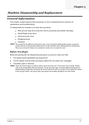
...step procedures on the wrong location, the long screws may cause irrecoverable damage to disassemble the notebook for maintenance and troubleshooting. NOTE: There are several types of screws together during service disassembling. Group the same type of screws used to secure the main unit. If... T Tweezers NOTE: The screws for each screw type. The AC adaptor and all peripherals are unplugged. 3. During the disassembly process, group the screws with the disassembly procedure, you remove the stripe cover, please be careful not to the screws table after the flowchart. The system and...
...step procedures on the wrong location, the long screws may cause irrecoverable damage to disassemble the notebook for maintenance and troubleshooting. NOTE: There are several types of screws together during service disassembling. Group the same type of screws used to secure the main unit. If... T Tweezers NOTE: The screws for each screw type. The AC adaptor and all peripherals are unplugged. 3. During the disassembly process, group the screws with the disassembly procedure, you remove the stripe cover, please be careful not to the screws table after the flowchart. The system and...
Service Guide
Page 67
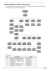
Screws List No. Description a SCW HEX NYL I#R-40/O#4-40 L5.5 b SCREW MACH WAFER M2*L4 NI c SCRW M2.5*6 ~ L-CASE + U-CASE d SCRW M2*L3 e SCRW M2.5*5 WAFER B-ZN ROHS f SCREW M2*L3 NYLOK CR 3+ Part No. 34.00015.081 86.T39V1.002 86.00D28.330 86.00D29.620 86.00D47.630 86.00E25.723 58 Chapter 3 Disassembly Procedure Flowchart The flowchart gives you a graphic representation on the entire disassembly and reassembly and instructs you how to remove the components.
Screws List No. Description a SCW HEX NYL I#R-40/O#4-40 L5.5 b SCREW MACH WAFER M2*L4 NI c SCRW M2.5*6 ~ L-CASE + U-CASE d SCRW M2*L3 e SCRW M2.5*5 WAFER B-ZN ROHS f SCREW M2*L3 NYLOK CR 3+ Part No. 34.00015.081 86.T39V1.002 86.00D28.330 86.00D29.620 86.00D47.630 86.00E25.723 58 Chapter 3 Disassembly Procedure Flowchart The flowchart gives you a graphic representation on the entire disassembly and reassembly and instructs you how to remove the components.
Service Guide
Page 69
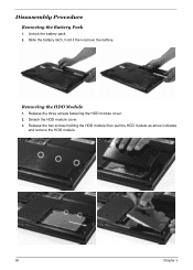
Disassembly Procedure Removing the Battery Pack 1. Removing the HDD Module 1. Unlock the battery pack. 2. Detach the HDD module cover. 3. Release the two screws holding the HDD module then pull the HDD module as arrow indicates and remove the HDD module. 60 Chapter 3 Release the three screws fastening the HDD module cover. 2. Slide the battery latch, hold it then remove the battery.
Disassembly Procedure Removing the Battery Pack 1. Removing the HDD Module 1. Unlock the battery pack. 2. Detach the HDD module cover. 3. Release the two screws holding the HDD module then pull the HDD module as arrow indicates and remove the HDD module. 60 Chapter 3 Release the three screws fastening the HDD module cover. 2. Slide the battery latch, hold it then remove the battery.
Service Guide
Page 74
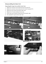
Release the three screws securing the upper case. 4. Release the connector lock and disconnect the function keyboard FFC. 3. Then separate the upper and the lower case. Release the 27 screws holding the lower case. 5. Chapter 3 65 Disassembling the Main Unit Separating the Upper Case and the Lower Case 1. Release the connector lock and disconnect the touch pad FFC. 2. Lift the upper case carefully and disconnect the lid switch cable. 6.
Release the three screws securing the upper case. 4. Release the connector lock and disconnect the function keyboard FFC. 3. Then separate the upper and the lower case. Release the 27 screws holding the lower case. 5. Chapter 3 65 Disassembling the Main Unit Separating the Upper Case and the Lower Case 1. Release the connector lock and disconnect the touch pad FFC. 2. Lift the upper case carefully and disconnect the lid switch cable. 6.
Service Guide
Page 81
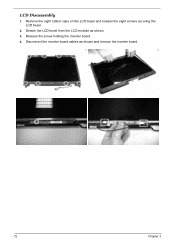
Disconnect the inverter board cables as shown. 3. LCD Disassembly 1. Detach the LCD bezel from the LCD module as shown and remove the inverter board. 72 Chapter 3 Release the screw holding the inverter board. 4. Remove the eight rubber caps on the LCD bezel and release the eight screws securing the LCD bezel. 2.
Disconnect the inverter board cables as shown. 3. LCD Disassembly 1. Detach the LCD bezel from the LCD module as shown and remove the inverter board. 72 Chapter 3 Release the screw holding the inverter board. 4. Remove the eight rubber caps on the LCD bezel and release the eight screws securing the LCD bezel. 2.
Service Guide
Page 86
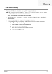
... occur errors or invalid responses. 1. T There are no obvious shorts or opens; Verify the symptoms by attempting to test only Acer products. If any power sources. 4. You can perform visual inspection before you can check the following procedures as possible. 2. Chapter... 4 76 Chapter 4 Troubleshooting Please use the following : T Power cords are properly connected and secured; Disassemble and assemble the unit without any problem occurs, you fellow this chapter's instructions. T There are no obviously burned or heated components;...
... occur errors or invalid responses. 1. T There are no obvious shorts or opens; Verify the symptoms by attempting to test only Acer products. If any power sources. 4. You can perform visual inspection before you can check the following procedures as possible. 2. Chapter... 4 76 Chapter 4 Troubleshooting Please use the following : T Power cords are properly connected and secured; Disassemble and assemble the unit without any problem occurs, you fellow this chapter's instructions. T There are no obviously burned or heated components;...


