
Service Guide
Page 17
Note NOTE: Do not cover or obstruct the opening of the fan. Houses the computer's main memory. 8 Chapter 1 Enable the computer to an Ethernet 10/100/1000-based networks. Houses ... NoCteo:nnects to a television or display device with S-video input # Icon Item Description 2 External display (VGA) port Connects to an external display device (e.g., external monitor, LCD projector). 3 Modem (RJ-11) port Connects to a phone line. 4 Ethernet (RJ-45) port 5 N/A Battery Connects to stay cool, even after prolonged use. Base View # Icon...
Note NOTE: Do not cover or obstruct the opening of the fan. Houses the computer's main memory. 8 Chapter 1 Enable the computer to an Ethernet 10/100/1000-based networks. Houses ... NoCteo:nnects to a television or display device with S-video input # Icon Item Description 2 External display (VGA) port Connects to an external display device (e.g., external monitor, LCD projector). 3 Modem (RJ-11) port Connects to a phone line. 4 Ethernet (RJ-45) port 5 N/A Battery Connects to stay cool, even after prolonged use. Base View # Icon...

Service Guide
Page 36
...-by. DC mode To suit your own profiles. To launch it, select Acer ePower Management from the Empowering Technology interface, or double click the Acer ePower Management icon in the task tray. You can adjust CPU speed, LCD brightness and other settings, or click on buttons to : • Set ...alarms. • Reload factory defaults. • Select what actions will be taken when the cover is "Maximum Performance." You ...
...-by. DC mode To suit your own profiles. To launch it, select Acer ePower Management from the Empowering Technology interface, or double click the Acer ePower Management icon in the task tray. You can adjust CPU speed, LCD brightness and other settings, or click on buttons to : • Set ...alarms. • Reload factory defaults. • Select what actions will be taken when the cover is "Maximum Performance." You ...

Service Guide
Page 82
Remove the antenna from the LCD cover. Chapter 3 73 Detach the LCD panel carefully and reverse it as shown. 7. Tear off the tapes holding the LCD panel cable carefully then disconnect the LCD panel. 8. Release the four screws securing the LCD panel. 6. 5.
Remove the antenna from the LCD cover. Chapter 3 73 Detach the LCD panel carefully and reverse it as shown. 7. Tear off the tapes holding the LCD panel cable carefully then disconnect the LCD panel. 8. Release the four screws securing the LCD panel. 6. 5.

Service Guide
Page 84
Push the CCD module upper case a little bit. 15. Release the two screws holding the CCD module and carefully pull the CCD module cable and LCD cable through the latch bar and LCD cover. 12. 11. Remove the CCD module cap. 13. Chapter 3 75 Then Separate the lower case from the upper case. 16. Remove the CCD module ring. 14. Release the screw holding the CCD module board the detach the CCD module board.
Push the CCD module upper case a little bit. 15. Release the two screws holding the CCD module and carefully pull the CCD module cable and LCD cable through the latch bar and LCD cover. 12. 11. Remove the CCD module cap. 13. Chapter 3 75 Then Separate the lower case from the upper case. 16. Remove the CCD module ring. 14. Release the screw holding the CCD module board the detach the CCD module board.
Service Guide
Page 100
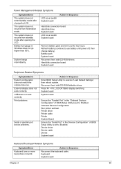
...display switching System board System board Ensure the "Parallel Port" in Sequence Hard disk connection board Hard disk drive System board LCD cover switch System board Remove battery pack and let it cool for two hours. Hard disk connection board System board Peripheral-Related .../Error System configuration does not match the installed devices. The system does not resume from standby mode after closing the LCD. Keyboard System board Chapter 4 90 LCD cover switch System board Action in the "Onboard Devices Configuration" of BIOS Setup Utility is set to use battery until power...
...display switching System board System board Ensure the "Parallel Port" in Sequence Hard disk connection board Hard disk drive System board LCD cover switch System board Remove battery pack and let it cool for two hours. Hard disk connection board System board Peripheral-Related .../Error System configuration does not match the installed devices. The system does not resume from standby mode after closing the LCD. Keyboard System board Chapter 4 90 LCD cover switch System board Action in the "Onboard Devices Configuration" of BIOS Setup Utility is set to use battery until power...

Service Guide
Page 119
...W02" Description "INVERTER 17"" YEC YNVW02" Acer Part No. 19.TB2V1.001 BOARDS BOARDS CABLES CAMERA INVERTER BOARD DARFON VK.21189.402 "INVERTER BOARD 17"" O2 V189-601" "LCD CABLE 17.1"" WXGA" CAMERA CMOS 300K VFA BN2QA350K8SD79 LCD BRACKET RIGHT INVERTER 17'' VK.21189.402...AEFV1.003 56.ADFV1.001 33.ADFV1.001 LCD BARCKET LEFT BRKT-L LCD MYALL-2 33.ADFV1.002 CASE/COVER/ BRACKET ASSEMBLY CASE/COVER/ BRACKET ASSEMBLY CASE/COVER/ BRACKET ASSEMBLY CASE/COVER/ BRACKET ASSEMBLY CASE/COVER/ BRACKET ASSEMBLY CASE/COVER/ BRACKET ASSEMBLY CASE/COVER/ BRACKET ASSEMBLY CAMERA LATCH CAMERA UPPER CASE...
...W02" Description "INVERTER 17"" YEC YNVW02" Acer Part No. 19.TB2V1.001 BOARDS BOARDS CABLES CAMERA INVERTER BOARD DARFON VK.21189.402 "INVERTER BOARD 17"" O2 V189-601" "LCD CABLE 17.1"" WXGA" CAMERA CMOS 300K VFA BN2QA350K8SD79 LCD BRACKET RIGHT INVERTER 17'' VK.21189.402...AEFV1.003 56.ADFV1.001 33.ADFV1.001 LCD BARCKET LEFT BRKT-L LCD MYALL-2 33.ADFV1.002 CASE/COVER/ BRACKET ASSEMBLY CASE/COVER/ BRACKET ASSEMBLY CASE/COVER/ BRACKET ASSEMBLY CASE/COVER/ BRACKET ASSEMBLY CASE/COVER/ BRACKET ASSEMBLY CASE/COVER/ BRACKET ASSEMBLY CASE/COVER/ BRACKET ASSEMBLY CAMERA LATCH CAMERA UPPER CASE...

Service Guide
Page 120
... MYALL-2" 50.AEFV1.003 CAMERA CAMERA CMOS 300K VFA BN2QA350K8SD79 CAMERA CMOS VFA BN2QA350K8SD79 56.ADFV1.001 CASE/COVER/ BRACKET ASSEMBLY LCD BRACKET RIGHT BRKT-R LCD MYALL-2 33.ADFV1.001 CASE/COVER/ BRACKET ASSEMBLY LCD BARCKET LEFT BRKT-L LCD MYALL-2 33.ADFV1.002 CASE/COVER/ BRACKET ASSEMBLY CAMERA LATCH LATCH CAMERA HINGH KIRKINI 33.AEFV1.001 CASE... DARFON INVERTER 17'' VK.21189.402 19.TCBV1.001 VK.21189.402 BOARDS "INVERTER BOARD 17"" O2 "INVERTER 17"" O2 V189- Category Part Name Description Acer Part No.
... MYALL-2" 50.AEFV1.003 CAMERA CAMERA CMOS 300K VFA BN2QA350K8SD79 CAMERA CMOS VFA BN2QA350K8SD79 56.ADFV1.001 CASE/COVER/ BRACKET ASSEMBLY LCD BRACKET RIGHT BRKT-R LCD MYALL-2 33.ADFV1.001 CASE/COVER/ BRACKET ASSEMBLY LCD BARCKET LEFT BRKT-L LCD MYALL-2 33.ADFV1.002 CASE/COVER/ BRACKET ASSEMBLY CAMERA LATCH LATCH CAMERA HINGH KIRKINI 33.AEFV1.001 CASE... DARFON INVERTER 17'' VK.21189.402 19.TCBV1.001 VK.21189.402 BOARDS "INVERTER BOARD 17"" O2 "INVERTER 17"" O2 V189- Category Part Name Description Acer Part No.

Service Guide
Page 121
...Acer Part No. LK.17106.002 LTN170WX-L05-H GLARE" H GLARE" LCD "LCD 17"" WXGA+ AU B170PW03 V4 GLARE" "LCD 17""WXGA B170PW03 LK.17105.005 V4 GLARE" LCD "LCD 17"" WXGA+ LG LP171WP4-TL02 GLARE" "LCD 17""W LP171WP4-TL02 LK.17008.015 GLARE" LCD "LCD 17""WXGA+ QDI QD17TL02-06 GLARE" "LCD...DDRII667 SAMSUNG M470T2953CZ3CE6 SODIMM 1G M470T2953CZ3- CASE/COVER/ BRACKET ASSEMBLY LCD HINGE PACK LEFT/ RIGHT LCD HINGE PACK LEFT/ RIGHT 6K.ADFV1.001 CASE/COVER/ BRACKET ASSEMBLY "LCD BEZEL 17.1"" W/LOGO" ASSY LCD BEZEL MYALL2 60.AEFV1.004 CASE/COVER/ BRACKET ASSEMBLY CAMERA LOWER CASE ASSY ...
...Acer Part No. LK.17106.002 LTN170WX-L05-H GLARE" H GLARE" LCD "LCD 17"" WXGA+ AU B170PW03 V4 GLARE" "LCD 17""WXGA B170PW03 LK.17105.005 V4 GLARE" LCD "LCD 17"" WXGA+ LG LP171WP4-TL02 GLARE" "LCD 17""W LP171WP4-TL02 LK.17008.015 GLARE" LCD "LCD 17""WXGA+ QDI QD17TL02-06 GLARE" "LCD...DDRII667 SAMSUNG M470T2953CZ3CE6 SODIMM 1G M470T2953CZ3- CASE/COVER/ BRACKET ASSEMBLY LCD HINGE PACK LEFT/ RIGHT LCD HINGE PACK LEFT/ RIGHT 6K.ADFV1.001 CASE/COVER/ BRACKET ASSEMBLY "LCD BEZEL 17.1"" W/LOGO" ASSY LCD BEZEL MYALL2 60.AEFV1.004 CASE/COVER/ BRACKET ASSEMBLY CAMERA LOWER CASE ASSY ...


