TravelMate 6492/6492G User's Guide EN
Page 41
... battery pack (6-cell) 3-pin 65 W AC adapter • 2.5-hour rapid charge system-off • 3.0-hour charge-in-use 88-/89-key Acer FineTouch™ keyboard with 5º curve, inverted "T" cursor layout, 2.5 mm (minimum) key travel Dual navigation control, featuring Acer FineTrack™ with two FineTrack™ buttons and touchpad with 4-way scroll button Acer Bio...
... battery pack (6-cell) 3-pin 65 W AC adapter • 2.5-hour rapid charge system-off • 3.0-hour charge-in-use 88-/89-key Acer FineTouch™ keyboard with 5º curve, inverted "T" cursor layout, 2.5 mm (minimum) key travel Dual navigation control, featuring Acer FineTrack™ with two FineTrack™ buttons and touchpad with 4-way scroll button Acer Bio...

TravelMate 6492/6492G User's Guide EN
Page 81
...Contact your dealer or an authorized service center. Memory size mismatch Press (during POST) to enter the BIOS utility, then press Exit in alphabetical order together with common system problems. Read it before calling a...BIOS utility to more serious problems require opening up the computer. keyboard connected Keyboard interface error Contact your dealer or an authorized service center. contact your dealer or an authorized service center. Keyboard error or no Contact your dealer or authorized service center for assistance. Error messages Corrective action CMOS battery...
...Contact your dealer or an authorized service center. Memory size mismatch Press (during POST) to enter the BIOS utility, then press Exit in alphabetical order together with common system problems. Read it before calling a...BIOS utility to more serious problems require opening up the computer. keyboard connected Keyboard interface error Contact your dealer or an authorized service center. contact your dealer or an authorized service center. Keyboard error or no Contact your dealer or authorized service center for assistance. Error messages Corrective action CMOS battery...

Service Guide
Page 8
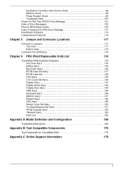
Boot ...57 Exit ...58 BIOS Flash Utility 59 Chapter 3 Machine Disassembly and Replacement 61 General Information 61 Before You Begin 61 Disassembly Procedure Flowcharts 62 Main Unit Disassembly Flowchart 62 LCM Module Disassembly Flowchart 63 Main Unit Disassembly Procedure 64 Removing the Battery Pack 64 Removing the CTO ...94 Replacing the BTCB Screws 95 Replacing the HDD 95 Replacing the ODD 95 Replacing the CTO Cover 96 Replacing the Battery Pack 96 Chapter 4 Troubleshooting 97 System Check Procedures 98 External Diskette Drive Check 98 External CD-ROM Drive Check 98 2
Boot ...57 Exit ...58 BIOS Flash Utility 59 Chapter 3 Machine Disassembly and Replacement 61 General Information 61 Before You Begin 61 Disassembly Procedure Flowcharts 62 Main Unit Disassembly Flowchart 62 LCM Module Disassembly Flowchart 63 Main Unit Disassembly Procedure 64 Removing the Battery Pack 64 Removing the CTO ...94 Replacing the BTCB Screws 95 Replacing the HDD 95 Replacing the ODD 95 Replacing the CTO Cover 96 Replacing the Battery Pack 96 Chapter 4 Troubleshooting 97 System Check Procedures 98 External Diskette Drive Check 98 External CD-ROM Drive Check 98 2
Service Guide
Page 9
...BIOS Beep Codes 105 Index of Symptom-to-FRU Error Message 110 Intermittent Problems 114 Undetermined Problems 115 Chapter 5 Jumper and Connector Locations 117 Connector Locations 117 Top View ...117 Bottom View ...118 Connector Pin Definitions 119 Chapter 6 FRU (Field Replaceable Unit) List 133 TravelMate 6492 Exploded Diagrams 134 3G Cover Ass'y 134 Battery... Set Ass'y 151 TPCB CaseSet Ass'y 152 Wireless Ass'y 154 Parts List ...155 Appendix A Model Definition and Configuration 166 TravelMate 6492 Series 166 Appendix B Test Compatible Components 175 Test Peripherals for...
...BIOS Beep Codes 105 Index of Symptom-to-FRU Error Message 110 Intermittent Problems 114 Undetermined Problems 115 Chapter 5 Jumper and Connector Locations 117 Connector Locations 117 Top View ...117 Bottom View ...118 Connector Pin Definitions 119 Chapter 6 FRU (Field Replaceable Unit) List 133 TravelMate 6492 Exploded Diagrams 134 3G Cover Ass'y 134 Battery... Set Ass'y 151 TPCB CaseSet Ass'y 152 Wireless Ass'y 154 Parts List ...155 Appendix A Model Definition and Configuration 166 TravelMate 6492 Series 166 Appendix B Test Compatible Components 175 Test Peripherals for...

Service Guide
Page 12
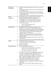
...• ACPI 3.0 CPU power management standard: supports Standby and Hibernation power-saving modes • 11.1V 3800 mAh Li-ion primary battery pack (6-cell) • 3-pin 90 W AC adapter • 2.5-hour rapid charge system-off • 3.0-hour charge-in-use Input ... cursor layout, 2.5 mm (minimum) key travel • Dual navigation control, featuring Acer FineTrack™ with two FineTrack™ buttons and touchpad with 4way scroll button • Acer Bio-Protection fingerprint reader supporting Acer FingerNav 4-way control function • 12 function keys, four cursor keys, two Windows&#...
...• ACPI 3.0 CPU power management standard: supports Standby and Hibernation power-saving modes • 11.1V 3800 mAh Li-ion primary battery pack (6-cell) • 3-pin 90 W AC adapter • 2.5-hour rapid charge system-off • 3.0-hour charge-in-use Input ... cursor layout, 2.5 mm (minimum) key travel • Dual navigation control, featuring Acer FineTrack™ with two FineTrack™ buttons and touchpad with 4way scroll button • Acer Bio-Protection fingerprint reader supporting Acer FingerNav 4-way control function • 12 function keys, four cursor keys, two Windows&#...
Service Guide
Page 69
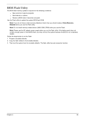
...you may not boot the system because the BIOS is required for the following conditions: q New versions of system programs q New features or options q Restore a BIOS when it becomes corrupted. Then boot the system from the bootable diskette. If the battery pack does not contain enough power to ...the bootable diskette. 3. Fellow the steps below to update the system BIOS flash ROM. The flash utility has auto-execution function. Note: Do not install ...
...you may not boot the system because the BIOS is required for the following conditions: q New versions of system programs q New features or options q Restore a BIOS when it becomes corrupted. Then boot the system from the bootable diskette. If the battery pack does not contain enough power to ...the bootable diskette. 3. Fellow the steps below to update the system BIOS flash ROM. The flash utility has auto-execution function. Note: Do not install ...
Service Guide
Page 112
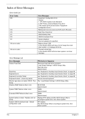
... Channel Master Drive Error (THe causes will show message. BIOS ROM System board DIMM System board DIMM System board Replace RTC battery and Run BIOS Setup Utility to reconfigure system time, then reboot system. 102 Chapter 4 CPU BIOS Update Code Mismatch 2. Unlock key switch Monitor type does not...: nnnn Extended RAM Failed at xxxx:xxxx:xxxxh (R:xxxxh, W:xxxxh) Real Time Clock Error CMOS Battery Bad CMOS Checksum Error System disabled. Battery critical LOW In this situation BIOS will shut down system, no message will be shown before "Equipment Configuration Error") Memory Error at ...
... Channel Master Drive Error (THe causes will show message. BIOS ROM System board DIMM System board DIMM System board Replace RTC battery and Run BIOS Setup Utility to reconfigure system time, then reboot system. 102 Chapter 4 CPU BIOS Update Code Mismatch 2. Unlock key switch Monitor type does not...: nnnn Extended RAM Failed at xxxx:xxxx:xxxxh (R:xxxxh, W:xxxxh) Real Time Clock Error CMOS Battery Bad CMOS Checksum Error System disabled. Battery critical LOW In this situation BIOS will shut down system, no message will be shown before "Equipment Configuration Error") Memory Error at ...

Service Guide
Page 113
... size found FRU/Action in Sequence RTC battery Run BIOS Setup Utility to reconfigure system time, then reboot system. RTC battery System board Run "Load Default Settings" in BIOS Setup Utility. RTC battery System board DIMM BIOS ROM System board None BIOS ROM System board Run "Load Default Settings" in BIOS Setup Utility. DIMM System board Check the...
... size found FRU/Action in Sequence RTC battery Run BIOS Setup Utility to reconfigure system time, then reboot system. RTC battery System board Run "Load Default Settings" in BIOS Setup Utility. RTC battery System board DIMM BIOS ROM System board None BIOS ROM System board Run "Load Default Settings" in BIOS Setup Utility. DIMM System board Check the...

Service Guide
Page 120
... Symptom / Error Indicator incorrectly remains off . See "Power System Check" on , but system runs correctly Action in Sequence Power source (battery pack and power adapter). Keyboard (if contrast and brightness function key doesn't work LCD is too dark LCD brightness cannot be adjusted LCD ...contrast cannot be adjusted Unreadable LCD screen Missing pels in Sequence Enter BIOS Utility to execute "Load Setup Default Settings", then reboot system. Battery pack Power adapter Hard drive & battery connection board System board Power source...
... Symptom / Error Indicator incorrectly remains off . See "Power System Check" on , but system runs correctly Action in Sequence Power source (battery pack and power adapter). Keyboard (if contrast and brightness function key doesn't work LCD is too dark LCD brightness cannot be adjusted LCD ...contrast cannot be adjusted Unreadable LCD screen Missing pels in Sequence Enter BIOS Utility to execute "Load Setup Default Settings", then reboot system. Battery pack Power adapter Hard drive & battery connection board System board Power source...
Service Guide
Page 121
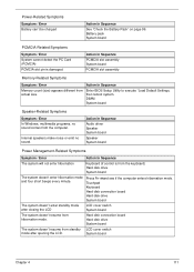
...standby LCD cover switch mode after closing the LCD LCD cover switch System board The system doesn't resume from actual size. Enter BIOS Setup Utility to execute "Load Default Settings, then reboot system. Touchpad Keyboard Hard disk connection board Hard disk drive System board The... PCMCIA slot assembly Memory-Related Symptoms Symptom / Error Action in Sequence See "Check the Battery Pack" on page 99. Press Fn+oand see if the computer enters hibernation mode. Battery pack System board PCMCIA-Related Symptoms Symptom / Error System cannot detect the PC Card (...
...standby LCD cover switch mode after closing the LCD LCD cover switch System board The system doesn't resume from actual size. Enter BIOS Setup Utility to execute "Load Default Settings, then reboot system. Touchpad Keyboard Hard disk connection board Hard disk drive System board The... PCMCIA slot assembly Memory-Related Symptoms Symptom / Error Action in Sequence See "Check the Battery Pack" on page 99. Press Fn+oand see if the computer enters hibernation mode. Battery pack System board PCMCIA-Related Symptoms Symptom / Error System cannot detect the PC Card (...

Service Guide
Page 122
... Symptom / Error Internal modem does not work . Refresh battery (continue use battery until power off, then charge battery). Printer driver Printer cable Printer System Board Ensure the "Serial Port" in the Devices Configuration" of BIOS Setup Utility is set to Enabled. Keyboard System board Reconnect...error in Windows doesn't go higher than 90%. Reconnect hard disk/CD-ROM/diskette drives. Battery pack System board Reconnect hard disk/CD-ROM drives. Action in Sequence Enter BIOS Setup Utility to Enabled. USB does not work correctly Print problems. Serial or parallel port...
... Symptom / Error Internal modem does not work . Refresh battery (continue use battery until power off, then charge battery). Printer driver Printer cable Printer System Board Ensure the "Serial Port" in the Devices Configuration" of BIOS Setup Utility is set to Enabled. Keyboard System board Reconnect...error in Windows doesn't go higher than 90%. Reconnect hard disk/CD-ROM/diskette drives. Battery pack System board Reconnect hard disk/CD-ROM drives. Action in Sequence Enter BIOS Setup Utility to Enabled. USB does not work correctly Print problems. Serial or parallel port...


